Article

Deception Velocity-Based Method to Discriminate Physical Targets and Active False Targets in a Multistatic Radar System

1
Hangzhou Institute of Technology, Xidian University, Hangzhou 311200, China
2
School of Electronics and Information Engineering, Hangzhou Dianzi University, Hangzhou 310018, China
3
School of Electronic Engineering, Xidian University, Xi’an 710071, China
4
National Laboratory of Radar Signal Processing, Xidian University, Xi’an 710071, China
5
State Key Laboratory of Millimeter Waves, School of Information Science and Engineering, Southeast University, Nanjing 210096, China
6
Institute of Electromagnetic Space, Southeast University, Nanjing 210096, China
7
Purple Mountain Laboratory, Nanjing 211100, China
*
Author to whom correspondence should be addressed.
Remote Sens. 2024, 16(2), 382; https://doi.org/10.3390/rs16020382
Submission received: 1 November 2023 / Revised: 29 December 2023 / Accepted: 3 January 2024 / Published: 18 January 2024

Abstract

:
Due to the silent operation of the receiver station in a multistatic radar system, it is difficult for the jammer to generate the cooperative active deception target for the multistatic radar system. Making use of the spatial diversity property, a data level fusion method is proposed to counter the active deception jamming in this paper. According to the spatial correlation difference in physical target and active false target motion states, the deception velocity of the physical target, which is obtained by the radial velocity of each receiver, obeys the Gaussian distribution with zero mean, and the one of the active false target obeys the Gaussian distribution with the mean being its true deception velocity. Based on this fact, the active false target and physical target are discriminated by the deception velocity testing. The proposed deception velocity-based (DVB) method can keep a constant misjudgment probability for physical targets and discriminate active false targets effectively, especially in large deception velocity cases. The simulation verifies the feasibility and validity of the proposed discrimination method. Moreover, the proposed method can be combined with the location information association method to enhance the ability to discriminate the range–velocity joint deception of false targets.

Graphical Abstract

1. Introduction

The radar electronic countermeasure (ECM) interferes with the normal operation of radar by confusing the physical targets (PTs) with the false targets (FTs) and/or drowning PTs in the interference signal, which seriously hinders the detection and tracking of the target [1]. With the application and development of digital radio frequency memory (DRFM), active deception jamming has become an efficient and widely used means of ECM. The repeater jammer performs the time delay, doppler and radar cross section (RCS) modulation on the intercepted radar signal to generate various false targets that resemble the physical target in multiple dimensions, such as range deception FT, velocity deception FT and range velocity joint deception FT [2,3]. The electronic counter-countermeasures (ECCMs) for active deception jamming have been developing from the early monostatic radar system to the distributed multistatic radar system [4,5]. Compared with the monostatic radar with limited resources, the multistatic radar system can perceive the environment from multiple dimensions and perspectives and benefits from fusion processing, therefore improving the performance on target detection [6,7], target tracking [8,9] and ECCM [10,11].
The multistatic radar system can suppress jamming signals or discriminate false targets by fusing and processing the redundant detection information of different receivers. According to the difference in fusion processing, the ECCM for active deception jamming can be categorized into data-level fusion methods and signal-level fusion methods [12].
For data-level fusion methods, the target measurement information in each receiver is sent to the fusion center for fusion processing, which includes the primary and filtered information, such as radial distance, angle, radial velocity and the track information. The data-level fusion is mainly based on the spatial correlation difference between physical and active false targets [13]. For the physical target, its motion states (location and velocity vector) converted by each local measurement information are approximately the same in the unified coordinate system. Due to the silent operation of the receiver station in the multistatic radar system, it is difficult for the jammer to generate the cooperative active deception target for the whole multistatic radar system. As a result, the converted motion states are generally scattered in the unified coordinate system.
At first, only the spatial correlation of location is made use of to discriminate false targets. According to the difference in location correlation between physical and false targets, a common origin test method, namely the location information association (LIA) method, is proposed based on Mahalanobis distance to discriminate false targets in a T/R-R bistatic radar architecture in [14]. Aiming at multiple false targets, the nearest neighbor association is firstly performed to avoid the target combination explosion, and then a dot association algorithm is designed with an adaptive threshold for homologous detection in [15]. Besides the nearest neighbor association with location, a discrimination process is presented based on nearest neighbor angle information to reduce the computational complexity and improve the target discrimination probability in [16]. Then, the spatial correlation of the velocity vector is utilized to discriminate false targets. For velocity deception false targets, the Doppler frequency of the same false target in each receiver station is similar when the jammer is stationary or moves slowly; meanwhile, that of the same physical target usually varies with receivers, which is exploited to discriminate false targets in [17]. Combining the spatial correlation of location and velocity vector, a discrimination method is proposed within the Doppler domain and range domain to counter range–velocity joint deception jamming in [18]. However, the velocity effect of the jammer is not dealt with on the discrimination performance of the methods [17,18]. Location information association and velocity vector association (VVA) are performed successively to enhance the ability to discriminate the range–velocity joint deception false targets for active radar networks in [19]. Besides the above dot fusion methods for centralized fusion structure, many ECCMs are also studied for distributed fusion architecture within the target tracking process against false targets in [20,21,22]. Compared with the track fusion methods, the dot fusion methods make use of more raw measurement information.
For signal-level fusion methods, the targeted whole or partial echo signals are sent to the fusion center for fusion processing from each receiver. The signal-level fusion methods are mainly based on the difference of spatial scattering characteristics between physical and active false targets. For the physical target, its echoes are de-correlated in distributed radar stations due to its RCS fluctuating randomly with a different line of sight (LOS) [23,24]. But for the active false target with the same source, although the transmission loss and received gain may vary with receivers, its jamming signals are still highly correlated in each receiver [25]. Based on the difference of spatial scattering characteristics, interference cancellation [26], jamming blocking [27] and correlation test [28,29,30] are proposed to suppress jamming signals or discriminate false targets. The cluster analysis method [31] and convolutional neural network [32] are also introduced to feature extraction and target discrimination.
Although the signal-level fusion methods have better performance than the data-level fusion methods, the former puts forward higher requirements for system synchronization and information transmission. Moreover, they are not two completely separate parts. The data-level fusion methods can be the preprocessing of the signal-level fusion methods, providing and lessening the discrimination scope of the latter. Compared with signal-level fusion methods, the data-level fusion methods are generally more concise and intuitive and easy to engineer implementation with [21,22]. Therefore, a data-level fusion method is proposed to counter the active deception jamming in this paper. The signal model and measurement model are first established for multistatic radar systems. According to the spatial correlation difference in physical target and active false target motion states, the statistical properties of the deception velocity are dealt with for the physical target and false target. It is found that the deception velocity obtained from the radial velocity of the physical target follows a Gaussian distribution with a zero mean. Conversely, for the active false target, the deception velocity conforms to a Gaussian distribution with a mean equivalent to its true deception velocity. Based on this fact, a data-level fusion method is proposed to discriminate the active false target and physical target by deception velocity testing. The proposed deception velocity-based method can keep a constant misjudgment probability for physical targets and discriminate targets effectively, especially in large deception velocity cases.
The paper is organized as follows. Section 2 builds the signal model and measurement model for the multistatic radar system with joint range–velocity deception. The location information association method and the proposed deception velocity are dealt with in Section 3. The simulation results and analyses are provided in Section 4 to verify the validity and superiority of the proposed method. Section 5 draws the conclusions.

2. Multistatic Radar System Model

2.1. Signal Model

As shown in Figure 1, a multistatic radar system T/R-R N is considered in this paper with one transmitter/receiver T 1 and N receivers R n ( n = 1 , 2 , N ), which distribute widely over a given area. The transmitter is also one of the receivers, which can be denoted by R 0 . There is one physical target (PT) in the monitoring area of the multistatic radar system. To protect the target, a joint range–velocity deception false target (FT) is generated by the self-defense repeater jammer by delaying, modulating and retransmitting the intercepted radar signals.
The time and phase synchronization among the multistatic radar system have been assumed accomplished [33]. The signal received by the nth receiver, denoted by r n ( t ) , can be presented as
r n ( t ) = e n ( t ) + j n ( t ) + n n ( t )
where 0 t P R T , P R T is the length of a pulse repetition interval (PRI). e n ( t ) , j n ( t ) and n n ( t ) are the echo signal reflected by physical targets, deception jamming signal and internal noise, respectively. The ideal echo of physical targets e n ( t ) can be modeled as
e n ( t ) = α n exp j 2 π ( f 0 f d n ) t τ n s t τ n
where α n = λ σ n P T G T G n / ( 4 π 4 π R T R n ) accounts for the complex amplitude of the physical target PT. P T is the transmitted power of the transmitter. G T and G n are the antenna gain of the transmitter and the nth receiver, respectively. It is obvious that R T = R 1 . σ n is the radar cross section (RCS) of PT with regard to the nth receiver. R T and R R n are the range from the transmitter to PT, and the one from PT to the nth receiver, respectively. f 0 = c / λ is the carrier frequency. The term c is the propagation speed of the electromagnetic wave and λ is the wavelength. τ n = R T n / c is the time delay of the physical target PT. R T n = R T + R n is the range along the path from transmitter to nth receiver via the physical target PT. s ( t ) is the transmitted signal of the transmitter, which is assumed to be a narrow-band signal. f d n is the bistatic Doppler frequency of the physical target
f d n = v T r + v n r c
where v T r and v n r are the radial velocity of the PT with regard to the transmitter and the nth receiver.
The joint range–velocity deception jamming signal j n ( t ) can be represented as
j n ( t ) = β n exp j 2 π ( f 0 f d n ) t τ n s t τ n
where the term β n = γ λ P J G J G n / ( 4 π R n ) is the complex amplitude of the false target FT. P J and G J are the transmitted power and the antenna gain of the jammer, respectively. f d n is the bistatic Doppler frequency of the false target
f d n = v T r + v n r c + f d = f d n + f d
and τ n = τ n + τ is the actual time delay of the false target FT. γ , τ and f d are the jammer’s random complex amplitude modulation with unknown distribution, time delay and doppler frequency modulation for the intercepted radar signals to produce the false target FT.

2.2. Measurement Model

On the basis of the signal model established in the above subsection, the measurement models are introduced for physical targets and active false targets. In the multistatic radar system T/R-R N , as shown in Figure 1, the location coordinates of the receiver stations are Z R n = [ x n , y n , z n ] T ( n = 0 , 1 , , N ). The location and velocity vectors of the physical target are assumed as Z P T = [ x , y , z ] T and v P T = [ v x , v y , v z ] T , respectively. The measurement information of a target in the n-th recevier R n includes the bistatic radial distance sum ρ n , azimuth angle α n , pitch angle β n and bistatic radial velocity υ n . The measurement information can be expressed as
Ω = [ ρ n , α n , β n , υ n ] T = [ ρ n , α n , β n , υ n ] T + ω n
where ρ n , α n , β n and υ n are the corresponding true values. ω n is the measurement error vector whose elements are an independently distributed Gaussian distribution with zero mean, ω n N ( 0 4 × 1 , R e ) [21,34]. 0 n × 1 is an n × 1 all-zero vector. R e is the covariance matrix, R e = d i a g σ ρ , n 2 , σ α , n 2 , σ β , n 2 , σ υ , n 2 . σ ρ , n , σ α , n , σ β , n , and σ υ , n are the measurement error standard deviation values of the range, azimuth angle, pitch angle and radial speed in the receiver R n , respectively.
For the physical target, the geometrical relationship between the physical radar and the bistatic T/R-R n can be represented as
ρ n = R T + R n = R 0 + R n = Z R 0 Z P T + Z R n Z P T α n = arctan y y R n x x R n β n = arctan z z R n ( x x R n ) 2 + ( y y R n ) 2 υ n = υ T r + υ n r 2 = υ 0 r + υ n r 2 = v P T , e R 0 + v P T , e R n 2
where arctan is the inverse function of the tangent. R n and υ n r are the range and the radial velocity of the PT with regard to the receiver R n , respectively. u = u , u is the norm of the vector u . u 1 , u 2 = u 1 T u 2 is the inner product between two vectors u 1 and u 2 . e R n the unit vector from the target pointing receiver Rn
e R n = [ cos α n cos β n , sin α n cos β n , sin β n ] T
For the joint range–velocity deception false target generated by the self-defense repeater jammer of the physical target, the geometrical relationship between the physical radar and the bistatic T/R-R n can be represented as
ρ n = R T + R n + R D = Z R 0 Z P T + Z R n Z P T + R D α n = arctan y y R n x x R n β n = arctan z z R n ( x x R n ) 2 + ( y y R n ) 2 υ n = υ T r + υ n r + υ D 2 = v P T , e R 0 + v P T , e R n + υ D 2
where R D and υ D are the corresponding deception range and velocity caused by the jammer’s time delay modulation τ and doppler frequency modulation f d for the intercepted radar signals to generate the FT.
Comparing the geometric relationship of PT with that of FT, it is precisely because of R D and υ D that the converted location and velocity vectors of FT are generally “scattered” and not the same as PT centralized in the unified coordinate system.

3. Materials and Methods

Based on the multistatic radar system model discussed in Section 2, the velocity vector association (VVA) method and its disadvantages are introduced and dealt with firstly for multistatic radar architecture, and then the deception velocity-based (DVB) method is proposed to discriminate the range–velocity joint deception false targets.
When one target measurement set Ω is extracted from each receiver station, the measurement combination has three hypotheses as follows,
  • H 0 : The combination corresponds to the same physical target;
  • H 1 : The combination corresponds to the same active false target;
  • H 2 : The combination is composed of different PTs and/or FTs.

3.1. Velocity Vector Association (VVA) Discriminator

According to the spatial correlation of the physical target, the velocity vector is obtained first. Considering that the velocity information obtained in each receiver is only the radial velocity, it will require the measurements of at least three receivers to calculate the velocity vector. From Equation (7), the relationship between the radial velocity and the target’s velocity vector v P T = [ v x , v y , v z ] T is represented as
v 0 v 1 v 2 = A 2 v x v y v z
where A is the transformation matrix.
A = 2 cos α 0 cos β 0 2 sin α 0 cos β 0 2 sin β 0 cos α 0 cos β 0 + cos α 1 cos β 1 sin α 0 cos β 0 + sin α 1 cos β 1 sin β 0 + sin β 1 cos α 0 cos β 0 + cos α 2 cos β 2 sin α 0 cos β 0 + sin α 2 cos β 2 sin β 0 + sin β 2
Therefore, the target’s velocity vector v and its error covariance matrixes P v can be obtained as
v x v y v z = 2 A 1 v 0 v 1 v 2
and
P v = E [ d v d v T ]
By applying Equations (12) and (13), two velocity vectors v 1 and v 2 are obtained from the data measured by three receviers with T/R station, and the corresponding error covariance matrixes are P v 1 and P v 2 , respectively. The velocity vector association method selects the Mahalanobis distance between velocity vectors v 1 and v 2 as the discrimination factor
M v = ( v 1 v 2 ) T Σ v 1 ( v 1 v 2 )
where
Σ V = E ( d v 1 d v 2 ) ( d v 1 d v 2 ) T = P v 1 + P v 2 E d v 1 d v 2 T E d v 2 d v 1 T
When the velocity vectors v 1 and v 2 correspond to the same physical target, namely hypothesis H 0 , the Mahalanobis distance M v between v 1 and v 2 approximately follows the Chi-square distribution with 1 degree of freedom, namely M v χ 1 2 . The discriminator based on the velocity vector association is established by
M v H 12 H 0 η
where η is the discrimination threshold.
From the derivation process, not only two different velocity vectors of a target and the corresponding error covariance matrixes are required in the velocity vector association discriminator, but also the cross-variance matrixes E d v 1 d v 2 T and E d v 2 d v 1 T are needed to be calculated for the measurements of two receivers shared in the computation of the two velocity vectors.

3.2. Proposed Deception Velocity-Based (DVB) Discrimination Method

In order to solve the above problem of the cumbersome process and high computation, a deception velocity-based (DVB) discrimination method is proposed in the subsection.
When both receivers are located on the same baseline, scenarios within the radar system can be simplified through a coordinate system transformation. As shown in Figure 2, the multistatic plane is defined as the plane that is determined by the common baseline of the receivers and the target. The right-handed Cartesian coordinate is established in the multistatic plane with the origin and the x-axis unchanged.
In the new coordinate system, the physical target’s velocity vector can be written as v P T = [ v x , v y , v z ] T . The angle of the PT with respect to the receiver R n is denoted by θ n in the transformed coordinate system, which can be obtained by the geometrical relationship
cos θ n = cos α n cos β n θ n = arccos ( cos α n cos β n )
Considering the fact that the velocity component v z in the z -axis makes no contributions to the radial speed υ n . The relationship between the radial velocity and the velocity vector can be rewritten as
v 0 v 1 v 2 = 1 2 2 cos θ 0 2 sin θ 0 cos θ 0 + cos θ 1 sin θ 0 + sin θ 1 cos θ 0 + cos θ 2 sin θ 0 + sin θ 2 v x v y
and
v 0 v 1 v 2 = 1 2 2 cos θ 0 2 sin θ 0 1 cos θ 0 + cos θ 1 sin θ 0 + sin θ 1 1 cos θ 0 + cos θ 2 sin θ 0 + sin θ 2 1 v x v y v D
for the physical target and active false target, respectively.
For the physical target, it can be argued that there is a virtual deception velocity of zero value. Therefore, the relationship Equations (18) and (19) can be uniformly expressed as
v 0 v 1 v 2 = B 2 v x v y v D
where B is
B = 2 cos θ 0 2 sin θ 0 1 cos θ 0 + cos θ 1 sin θ 0 + sin θ 1 1 cos θ 0 + cos θ 2 sin θ 0 + sin θ 2 1
Then, the vector [ v x , v y , v D ] T can be obtained from Equation (20)
v x v y v D = 2 B 1 v 0 v 1 v 2 = 2 B * | B | v 0 v 1 v 2
where B * and | B | are the adjoint matrix and determinant of the matrix B , respectively. The deception velocity can be extracted as
v D = 2 B s 20 + s 01 + s 21 v 0 + 2 s 02 v 1 + 2 s 10 v 2
B = s 01 + s 12 + s 20
s i j = sin θ i θ j
and the estimation variance of the deception velocity is
σ v D 2 = E d v D d v D T = T Λ T T
where T is the partial derivative vector, which can be derived from Equations (17) and (23)
T = v D α 0 v D β 0 v D v 0 v D α 1 v D β 1 v D v 1 v D α 2 v D β 2 v D v 2
and Λ is the
Λ = diag σ α 0 2 , σ β 0 2 , σ v 0 2 , σ α 1 2 , σ β 1 2 , σ v 1 2 , σ α 2 2 , σ β 2 2 , σ v 2 2
Under hypothesis H 1 , although the true deception velocity v D , F T of the active false target is unknown, its estimation v ^ D , F T approximately follows a Gaussian distribution with mean v D , F T and variance σ v D 2 , namely v ^ D , F T N ( v D , F T , σ v D 2 ) . Meanwhile, under hypothesis H 0 , the virtual deception velocity v ^ D , P T of the physical target approximately follows a Gaussian distribution with zero mean and variance σ v D 2 , namely v ^ D , P T N ( 0 , σ v D 2 ) .
Therefore, the discrimination factor can be constructed as follows
μ = v d 2 σ v D 2
For physical targets, μ approximately follows the Chi-square distribution with 1 degree of freedom based on the analysis that the virtual deception velocity v ^ D , P T of the physical target follows a Gaussian distribution v ^ D , P T N ( 0 , σ v D 2 ) , namely H 0 : μ χ 1 2 [35]. Accordingly, the following hypothesis test is established
μ H 12 H 0 ε
where ε is the discrimination threshold, which is determined by the significance level κ of the hypothesis test
ε = Φ χ 1 2 1 ( 1 κ )
where Φ χ 1 2 1 is the inverse cumulative distribution function of the Chi-square distribution χ 1 2 with 1 degree of freedom. Actually, the significance level κ is namely the expected misjudgment probability of the physical target P P T , which is the expected probability that a physical target is judged as a false target. Therefore, the expected discrimination probability of the physical target P P T is
P P T = 1 P P T = 1 κ
As will be shown in the simulation section, the discrimination performance is affected by the deception speed, SNR/JNR, measurement accuracy and location. Therefore, in practice, the set of the expected misjudgment probability of the physical target P P T should take the prior information of the above factors into consideration. If the expected misjudgment probability of the physical target P P T is set too little, the false target cannot be discriminated effectively.
The discrimination criterion is set as
  • I. When all the combinations composed of one target in T/R 0 and all targets in R 1 and R 2 are judged to be H 12 , the target is discriminated to be an active false target;
  • II. When more than one target combination composed of one target is judged to be H 0 , the target combination with the minimum μ is reserved, and for one specific target, no more than one combination can pass the hypothesis testing to avoid ambiguity.
Compared with the VVA discriminator, the proposed DVB method directly makes use of the measurements to construct the discrimination statistics, reducing the complexity of the process. Moreover, the demand for the receiver number decreases by transforming the coordinate system to reduce the data dimension.
As shown in Figure 3, the processing flow of the proposed DVB method is summarized as follows:
  • Measurement Set Transformation: According to Equation (17), the origin measurement set Ω = [ ρ n , α n , β n , υ n ] T of every target is transformed into the new measurement set Ω = [ ρ n , θ , υ n ] T in each receiver;
  • Calculate Deception Velocity and Variance: Select one target measurement set from each receiver to form the target combination, and calculate the deception velocity and variance of all target combinations according to Equations (23) and (26);
  • Discrimination Statistic: Calculate the corresponding discrimination factors of both target combinations according to Equations (29);
  • Threshold Set: Based on the expected discrimination probability P P T or the expected misjudgement probability P P T , the threshold is set according to Equations (31) and (32);
  • Hypothesis Testing: For each target combination, the hypothesis testing threshold is performed according to Equation (30);
  • Target Discrimination: Finally, the physical and active false targets are discriminated according to the discrimination criterion.

4. Results and Discussion

In this section, the multistatic radar system composed of T/R 0 , R 1 and R 2 receivers is taken as an example to verify the feasibility and validity of the proposed discrimination method, and the effect of the related factors are analyzed on the discrimination performance. The location and measurement accuracies of each receiver are assumed as shown in Table 1. In the monitoring area of the multistatic radar system, there is a physical target with location coordinates [ 20 , 50 , 20 ] T km and velocity vectors [ 100 , 150 , 6 ] T m / s . To protect the physical target (PTs), the self-defense repeater jammer generates a joint range–velocity deception false target (FT) generated by delaying, modulating and retransmitting the intercepted radar signals.

4.1. Discrimination Performance

In this subsection, the effectiveness of the proposed discrimination method is verified by computer simulations. In the scenario set at the beginning of the section, the self-defense repeater jammer carried by the physical target generates an active false target with a deception distance of 1000 m. The deception velocity of FT varies from 50 m/s to 1000 m/s with an interval of 50 m/s. For each value of the deception velocity, 5000 Monto Carlo simulation experiments are performed to obtain the performance curves of the discrimination probability of PT and FT. The desired misjudgment probability of the physical target is set as P P T = 0.01 . The discrimination threshold can be obtained from Equation (31) as ε = 6.63 . For each value of deception velocity, the homologous detection method based on location information association (LIA) [13], the velocity vector association (VVA) discriminator, the proposed deception velocity-based (DVB) method and the combination method of location information association and deception velocity association (LIA-DVB) are performed to discriminate active false targets, which are denoted by LIA, VVA, DVB and LIA-DVB, respectively, in the simulation result of Figure 4. For comparison, the VVA discriminator is also derived into the multistatic plane. In Figure 4, the performance curves of the discrimination probability of PT P P T and that of FT P F T are given versus different deception velocities.
When there is a physical target and an active false target, the target combination composed of one target selected from each receiver has eight cases: H 0 —one case, H 1 —one case and H 2 —six cases. At this time, the principle of successful discrimination of physical and false targets is defined as follows: only when the combination {PT, PT, PT} is finally judged as H 0 , the physical target is considered successfully discriminated, and when any combination containing a false target is judged as H 0 , the false target will be considered misjudged. It can be seen from Figure 4a that the discrimination probability of the physical target of LIA remains near the expected value, 99%. According to the algorithm principle, its discrimination performance has nothing to do with the deception velocity. On the other hand, for VVA and DVB methods, the discrimination probability of the physical target increases with the deception velocity, and finally remains around the expected value, 99%. When the deception velocity is small, the velocity of the false target is similar to that of the physical target, and there are cases where the target combination of physical and false targets passes the hypothesis test.
It can be seen from Figure 4b that the discrimination probability of the LIA method for the false target is only near 54 % . With the increase in deception velocity, the discrimination probability of active false targets is gradually increased for both the VVA and DVB methods. Under the current parameter setting, when the deception velocity is 150 m/s, the discrimination probability of the two algorithms has reached 90.0 % ; when the deception velocity reaches 200 m/s, the discrimination probability can reach 99.0 % .
To further verify the superiority of the proposed method, the performance curves of these four methods are given versus different signal-to-noise ratios (SNRs) or jamming-to-noise ratios (JNRs) in Figure 5. Although the SNR or JNR has effects on the detection of targets, just the influence of SNR/JNR on the measurement accuracy of range, angle and radial velocity are taken into account in the simulation. Because the fixed random error and bias error are usually small, only the SNR/JNR-dependent measurement errors are considered [36]. The range resolution, velocity resolution and beamwidth are assumed to be 150 m, 10 m/s and 1°, respectively. SNR/JNR varies from 5 dB to 25 dB. The deception speed is set as 100 m/s.
It can be seen from Figure 5a that the physical target discrimination probability of the proposed DVB method slightly deviates from the expected value of 0.99 mainly due to the high measurement error of radial velocity when the value of SNR/JNR is small and fluctuates in the vicinity of the expected value with the increase in SNR/JNR. The superiority of the proposed DVB method is more obvious in the discrimination of false targets, as shown in Figure 5b. Due to the combination of LIA and DVB, the LIA-DVB method can improve the discrimination performance with small deception velocity cases when each of them has a decent discrimination ability.
It is worth noting that comparing the performance of the VVA and DVB in Figure 4 and Figure 5, their curves are closely approximated for both physical targets and active false targets. This is because the data used in both methods is the same, and the discrimination statistics of the physical targets obey the same distribution in both methods. However, as mentioned in Section 3.2, the DVB method is much more concise than the VVA method. The simulation results verify the feasibility and effectiveness of using the velocity information to identify the false target with range and velocity joint deception.

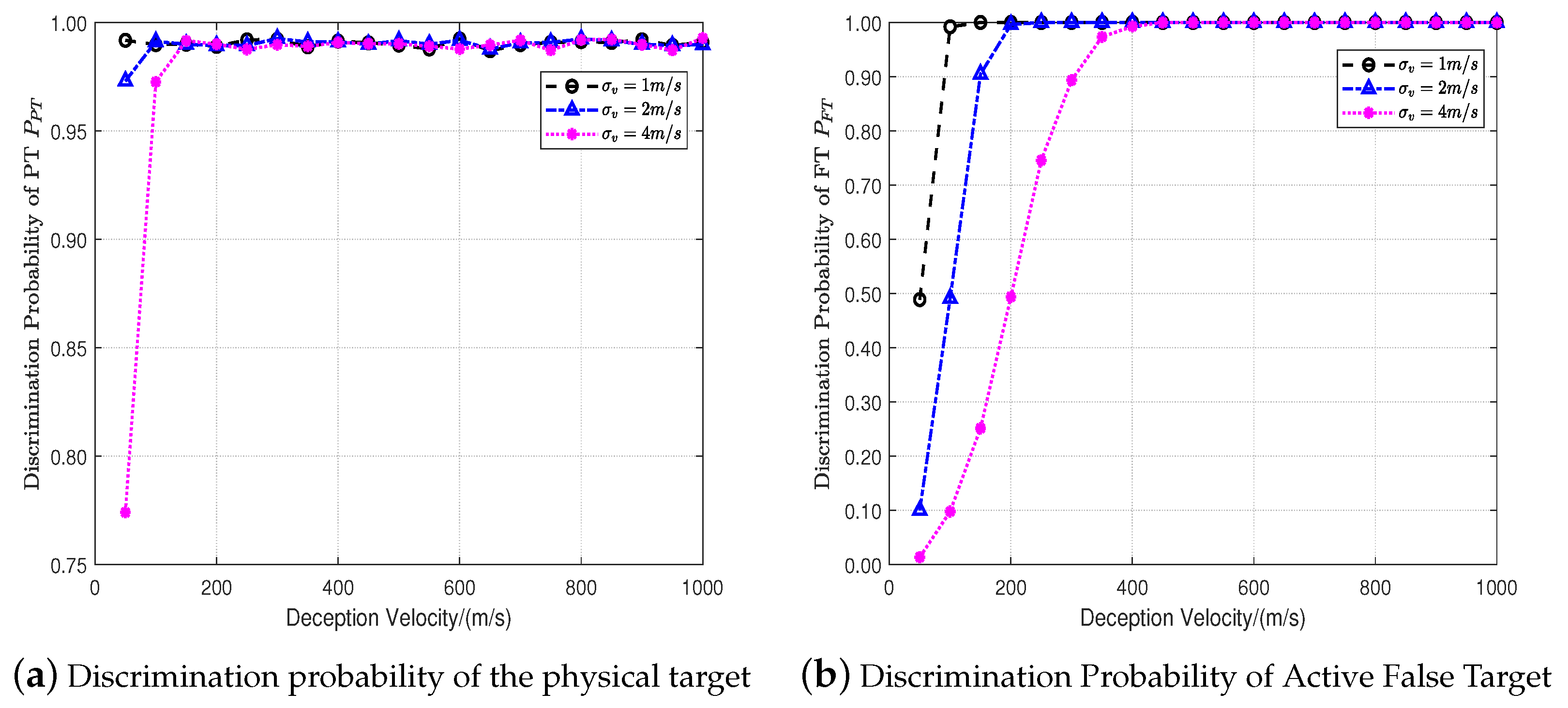
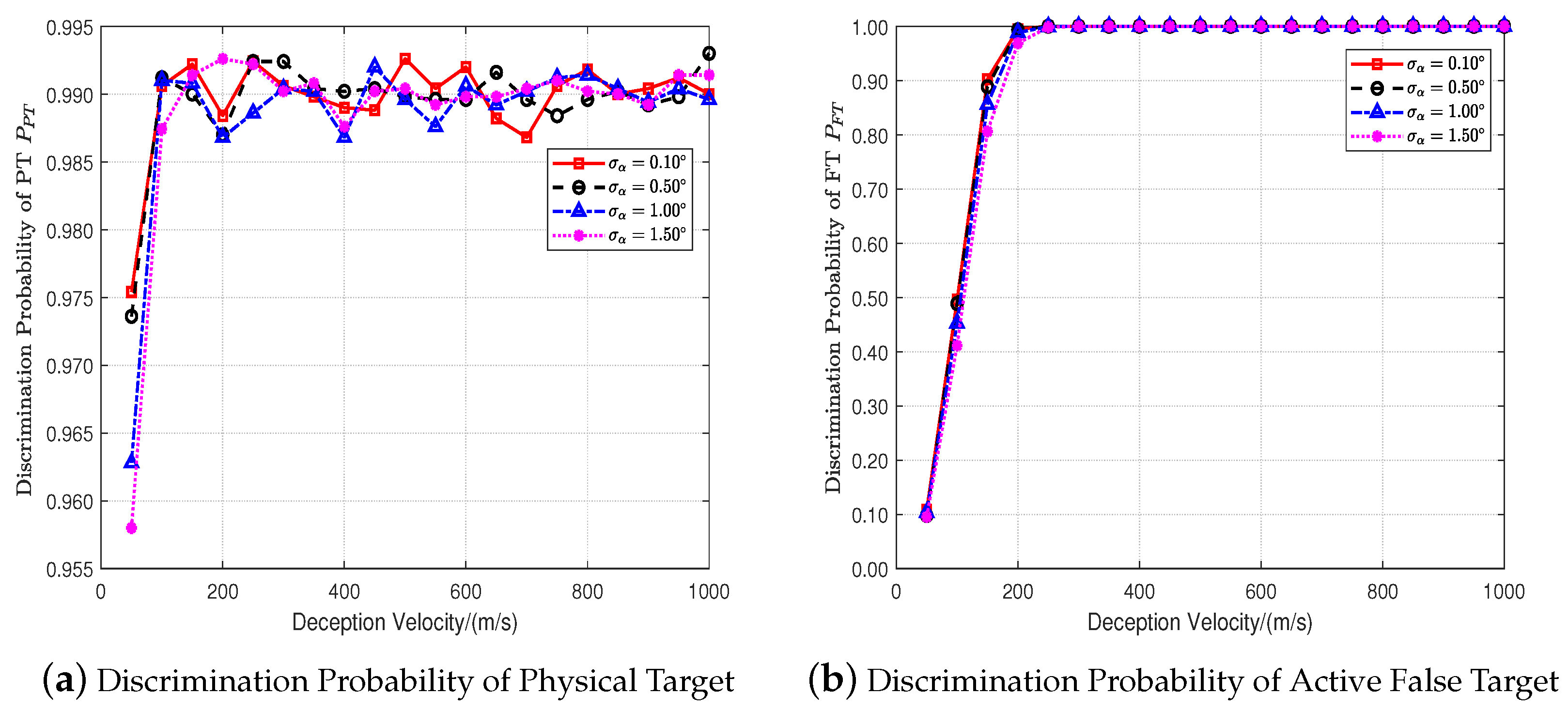
4.2. Influence of Measurement Accuracy on Discrimination Performance

This experiment simulates the discrimination performance of the DVB method with different velocity and angle measurement accuracies. Experimental parameters are set as shown in Table 1, and the velocity and angle accuracy of T/R, R 1 and R 2 stations are the same. During the simulation, the velocity and angle measurement accuracy of the multistatic radar system are changed, respectively, and other parameters are kept unchanged. The desired misjudgment probability of the physical target is also set as P P T = 0.01 . The discrimination threshold can be obtained from Equation (31) as ε = 6.63 .
In Figure 6, the discrimination probabilities of targets P P T and P F T are given as a function of deception velocity v D . The curves correspond to different velocity measurement accuracy σ v , where σ v = 1 m/s, 2 m/s and 4 m/s. All performance curves are obtained by averaging over 5000 independent Monte Carlo experiments at each value of v D .
It can be seen from Figure 6a that when the value of deception velocity is small, the radar velocity measurement accuracy has a significant impact on the discrimination probability of the physical target, and the higher the velocity measurement accuracy, the better the discrimination performance for the physical target. However, with the increase in deception velocity, the discrimination probability of the physical target gradually increases and remains around the expected discrimination probability of 99 % . For the three cases of velocity measurement accuracy, when the deception velocity is not less than 100 m/s, the discrimination probability of the physical target has reached the expected level, and then the constant misjudgment property is maintained for the physical target. Compared with the physical target, the discrimination performance for active false targets is very sensitive to the velocity measurement accuracy as shown in Figure 6b. The higher the measurement accuracy of the deception velocity, the higher the discrimination probability of the active false target. This is because the order of magnitude of the target velocity is relatively small, and the velocity error of a small value will cause a large deviation in the calculated velocity vector.
In Figure 7 and Figure 8, the discrimination probabilities of targets P P T and P F T are given as a function of deception velocity v D . The curves correspond to different azimuth and pitch angle measurement accuracy σ α and σ β , where the range of σ α and σ β are 0.10 ° , 0.50 ° , 1.00 ° and 1.50 ° . All performance curves are obtained by averaging over 5000 independent Monte Carlo experiments at each value of v D .
The simulation results show that the accuracy of angle measurement does not affect the discrimination performance dramatically. However, in the overall trend, the greater the accuracy of angle measurement, the better the discrimination performance of the proposed method. Comparing Figure 7 with Figure 8, the measurement accuracy of azimuth angle has a larger effect than that of pitch angle on the discrimination performance. This is because the variation of the radial velocity caused by the azimuth angle change is greater than that caused by an equivalent change of pitch angle. In the derivation process in Section 3.2, the receivers are assumed to be located on the common baseline. However, the insensitivity property of the performance to the azimuth and pitch angle makes the proposed method suitable for the case that receiver stations can be distributed within a certain area around the common baseline rather than located on the baseline exactly.
Based on the above experiment, the following conclusions can be drawn:
  • When the deception velocity is small, the higher the accuracy of the velocity measurement and angle measurement, the better the discrimination performance for the physical target. With the increase in deception velocity, the discrimination probability of the physical target gradually reaches near the expected probability and remains constant;
  • The higher the accuracy of velocity and angle measurement, the greater the deception velocity and the better the discrimination performance for active false targets.

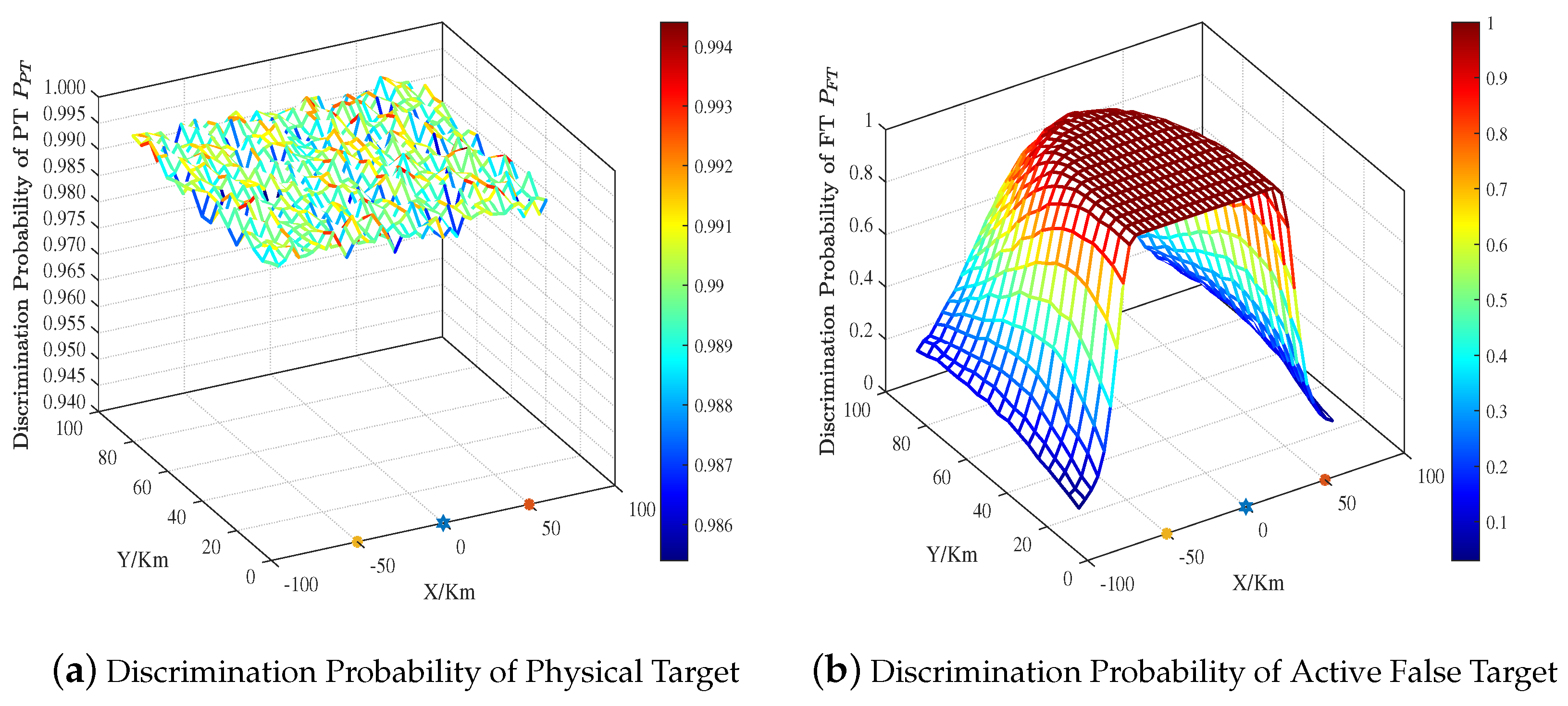
4.3. Effect of Target Location on Discrimination Performance

Finally, the discrimination performance of the DVB method is simulated and analyzed when the target performing self-defense jamming is located at different locations. The target position varies from 100 km to 100 km on the X-axis and from 20 km to 100 km on the Y-axis. The deception distance of the active false target generated by the jammer carried by the target is 1000 m, and the deception speed is 300 m/s. The measurement error information of the T/R-R 2 multistatic radar system is shown in Table 1. The X and Y coordinates of the target are in intervals with a step of 5 km, and 5000 Monte Carlo experiments are performed for each location of the target. The simulation results are shown in Figure 9. In the figure, ★ represents the T/R station, and ∗ represents the R station. The desired misjudgment probability of the physical target is set as P P T = 0.01 .
As shown in Figure 9a, within the illustrated airspace range, the discrimination probability of the proposed method is maintained at 99 % for the physical target, which is consistent with the expected constant misjudgment of the physical target. In Figure 9b, the high discrimination probability of the false target is mainly distributed in the area between two receivers, and radiates out from the baseline of the multistatic radar system, and the discrimination probability decreases with far distance. When the X coordinate of the target is less than the receiver R 2 (i.e., 50 km) or greater than receiver R 1 (i.e., 50 km), the discrimination performance decreases sharply. This is mainly because the difference in the angle of the target relative to each receiver in the above region becomes smaller, which increases the deviation of the target velocity and the deception velocity solution.

5. Conclusions

In this paper, a data-level fusion method is proposed to discriminate physical targets and active false targets in the multistatic radar system. On the basis of the signal model and measurement model of the multistatic system, the velocity vector association discriminator and its deficiency are introduced according to the spatial correlation difference in the physical target and active false target motion states. Aiming at the problem, the coordinate system transformation is performed first to reduce the demand for receivers. Based on the fact that the deception velocity of the physical target obeys the Gaussian distribution with zero mean and the active false target obeys the Gaussian distribution with the mean being its true deception velocity, the deception velocity-based method is proposed to discriminate the active false target and physical target. The proposed method can keep a constant misjudgment probability for physical targets and discriminate targets effectively, especially with large deception velocities. Moreover, the proposed method can be combined with the location information association method to further improve the discrimination performance. The simulation verifies the feasibility and superiority of the proposed discrimination method.

Author Contributions

Conceptualization, Q.L., Y.G. and H.X.; methodology, Q.L., Y.G. and L.Z.; software, Q.L., Z.C. and Y.G.; validation, P.Z., Z.C. and Y.H.; writing—original draft preparation, Q.L. and Y.G., funding acquisition, Q.L., H.X. and Z.C. All authors have read and agreed to the published version of the manuscript.

Funding

This work was supported in part by the Proof of Concept Foundation of Xidian University Hangzhou Institute of Technology under Grant XJ2023230036, in part by the Opening Project of Guangxi Key Laboratory of Wireless Wideband Communication and Signal Processing under Grant GXKL06230203 and in part by the National Natural Science Foundation of China under Grant 62001062 and 62301408.

Data Availability Statement

The datasets are available from the corresponding author upon reasonable request.

Conflicts of Interest

The authors declare no conflicts of interest.

Abbreviations

The following abbreviations are used in this manuscript:
ECCMelectronic counter-countermeasures
DRFMdigital radio frequency memory
PTphysical target
FTfalse target
LIAlocation information association method
VVAvelocity vector association method
DVBdeception velocity-based method
SNRsignal-to-noise ratio
JNRjamming-to-noise ratio

References

  1. Li, N.-J.; Zhang, Y.-T. A Survey of Radar ECM and ECCM. IEEE Trans. Aerosp. Electron. Syst. 1995, 31, 1110–1120. [Google Scholar] [CrossRef]
  2. Berger, S. Digital Radio Frequency Memory Linear Range Gate Stealer Spectrum. IEEE Trans. Aerosp. Electron. Syst. 2003, 39, 725–735. [Google Scholar] [CrossRef]
  3. Han, B.; Qu, X.; Yang, X.; Li, W.; Zhang, Z. DRFM-Based Repeater Jamming Reconstruction and Cancellation Method with Accurate Edge Detection. Remote Sens. 2023, 15, 1759. [Google Scholar] [CrossRef]
  4. Cui, G.; Yu, X.; Wei, W.; Xiong, K.; Kong, L.; Kong, Y. An overview of antijamming methods and future works on cognitive intelligent radar. J. Radar 2022, 11, 974–1002. [Google Scholar] [CrossRef]
  5. Ling, Q.; Huang, P.; Wang, D.; Xu, H.; Wang, L.; Liu, X.; Liao, G.; Sun, Y. Range Deception Jamming Performance Evaluation for Moving Targets in a Ground-Based Radar Network. Electronics 2023, 12, 1614. [Google Scholar] [CrossRef]
  6. Kanhere, O.; Goyal, S.; Beluri, M.; Rappaport, T.S. Target Localization Using Bistatic and Multistatic Radar with 5G NR Waveform. In Proceedings of the 2021 IEEE 93rd Vehicular Technology Conference (VTC2021-Spring), Helsinki, Finland, 25–28 April 2021; pp. 1–7. [Google Scholar] [CrossRef]
  7. Bo, Y.; Enrico, P.; Xu, L.; Lu, H. A Target Detection and Tracking Method for Multiple Radar Systems. IEEE Trans. Geosci. Remote Sens. 2022, 60, 1–21. [Google Scholar] [CrossRef]
  8. Chen, Y.; Wei, P.; Zhang, H.; You, M.; Li, W. Direct Target Joint Detection and Tracking Based on Passive Multi-Static Radar. Remote Sens. 2023, 15, 624. [Google Scholar] [CrossRef]
  9. Lu, R.; Liu, X.; Chen, X. Localization and Tracking of Multiple Fast Moving Targets in Bistatic MIMO Radar. Signal Process. 2023, 203, 108780. [Google Scholar] [CrossRef]
  10. Liu, J.; Gong, M.; Nie, Z.; Li, H.; Liu, J.; Zhao, S. Subset Selection Strategies Based on Target Positioning Characteristics for Anti-Jamming Technology. Remote Sens. 2022, 14, 6230. [Google Scholar] [CrossRef]
  11. Zhang, H.; Liu, W.; Zhang, Q.; Xie, J. Joint Resource Optimization for a Distributed MIMO Radar When Tracking Multiple Targets in the Presence of Deception Jamming. Signal Process. 2022, 200, 108641. [Google Scholar] [CrossRef]
  12. Zhang, L.; Zhao, S.; Zhou, Y.; Liu, N.; Zhang, J. Research Advance on Cooperative Anti-Deception Jamming in Netted Radar. J. Data Acquis. Process 2014, 29, 516–525. [Google Scholar] [CrossRef]
  13. Song, R.; Cheng, D.; Qi, W.; Xiang, L.; Jiang, Y. Research on Anti-Deceptive Jamming of Multi Station Fusion of Netted Radar. In Proceedings of the 2022 IEEE 10th Joint International Information Technology and Artificial Intelligence Conference (ITAIC), Chongqing, China, 17–19 June 2022; pp. 1732–1734. [Google Scholar] [CrossRef]
  14. Yang, L.; Xu, H.; Sun, Z. Identification Method of False-Targets in T/R-R Bistatic Radar System. J. Nationnal Univ. Def. 1997, 19, 1–7. [Google Scholar]
  15. Zhao, Y.; Wang, X.; Wang, G.; Liu, L.; Luo, J. Tracking Technique for Radar Network in the Presence of Multi-Range-False-Target Deception Jamming. ACTA Electron. Sin. 2007, 35, 454–458. [Google Scholar]
  16. Wang, G.; Ji, Z. Multi-range-false-target Jamming for Radar Network on Mutliple Disriminations. Syst. Eng. Electron. 2017, 39, 40–48. [Google Scholar]
  17. Bo, L.; Yao, S.; Zhou, C.-y. Study of Multistatic Radar against Velocity-Deception Jamming. In Proceedings of the 2011 International Conference on Electronics, Communications and Control (ICECC), Ningbo, China, 9–11 September 2011; pp. 1044–1047. [Google Scholar]
  18. Huang, D.; Cui, G.; Yu, X.; Ge, M.; Kong, L. Joint Range–Velocity Deception Jamming Suppression for SIMO Radar. IET Radar Sonar & Navig. 2019, 13, 113–122. [Google Scholar] [CrossRef]
  19. Zhao, S.; Zhang, L.; Zhou, Y.; Liu, N. Measurement Fusion Method against False-Target Jamming for Radar Network. J. Univ. Electron. Sci. Technol. China 2014, 43, 207–211. [Google Scholar]
  20. Zhu, Y.; Da, K.; Yang, Y.; Fu, Q. Multiple Active False Target Suppression Based on Distributed GM-PHD Filter. In Proceedings of the 2021 International Conference on Control, Automation and Information Sciences (ICCAIS), Xi’an, China, 14–17 October 2021; pp. 1053–1057. [Google Scholar] [CrossRef]
  21. Yang, Y.; Da, K.; Zhu, Y.; Fu, Q. Consensus-Based Distributed Target Tracking in the Presence of Active False Targets. In Proceedings of the 2021 IEEE 2nd International Conference on Big Data, Artificial Intelligence and Internet of Things Engineering (ICBAIE), Nanchang, China, 26–28 March 2021; pp. 753–757. [Google Scholar] [CrossRef]
  22. Yang, Y.; Da, K.; Zhu, Y.; Xiang, S.; Fu, Q. Consensus Based Target Tracking against Deception Jamming in Distributed Radar Networks. IET Radar Sonar & Navig. 2023, 17, 683–700. [Google Scholar] [CrossRef]
  23. Fishler, E.; Haimovich, A.; Blum, R.; Cimini, L.; Chizhik, D.; Valenzuela, R. Spatial Diversity in Radars—Models and Detection Performance. IEEE Trans. Signal Process. 2006, 54, 823–838. [Google Scholar] [CrossRef]
  24. Zhou, S.; Liu, H.; Zhao, Y.; Hu, L. Target Spatial and Frequency Scattering Diversity Property for Diversity MIMO Radar. Signal Process. 2011, 91, 269–276. [Google Scholar] [CrossRef]
  25. Chernyak, V.S. Adaptive Mainlobe Jamming Cancellation and Target Detection in Multistatic Radar Systems. In Proceedings of the International Radar Conference, Beijing, China, 8–10 October 1996; pp. 297–300. [Google Scholar] [CrossRef]
  26. Wang, B.; Cui, G.; Zhang, S.; Sheng, B.; Kong, L.; Ran, D. Deceptive Jamming Suppression Based on Coherent Cancelling in Multistatic Radar System. In Proceedings of the 2016 IEEE Radar Conference (RadarConf), Philadelphia, PA, USA, 2–6 May 2016; pp. 1–5. [Google Scholar] [CrossRef]
  27. Zhao, S.; Zhou, Y.; Zhang, L.; Guo, Y.; Tang, S. Discrimination between Radar Targets and Deception Jamming in Distributed Multiple-radar Architectures. IET Radar Sonar & Navig. 2017, 11, 1124–1131. [Google Scholar] [CrossRef]
  28. Zhao, S.; Zhang, L.; Zhou, Y.; Liu, N.; Liu, J. Discrimination of Active False Targets in Multistatic Radar Using Spatial Scattering Properties. IET Radar Sonar & Navig. 2016, 10, 817–826. [Google Scholar] [CrossRef]
  29. Li, Q.; Zhang, L.; Zhou, Y.; Zhao, S.; Liu, N.; Zhang, J. Discrimination of Active False Targets Based on Hermitian Distance for Distributed Multiple-Radar Architectures. IEEE Access 2019, 7, 71872–71883. [Google Scholar] [CrossRef]
  30. Sun, M.; Ding, C.; Zhang, S.; Lu, J.; Shao, P. Recognition of Deception Jamming Based on Statistical Correlation Difference in a Multistatic Radar System. J. Electron. Inf. Technol. 2020, 42, 2992–2998. [Google Scholar]
  31. Zhao, S.; Liu, N.; Zhang, L.; Zhou, Y.; Li, Q. Discrimination of Deception Targets in Multistatic Radar Based on Clustering Analysis. IEEE Sens. J. 2016, 16, 2500–2508. [Google Scholar] [CrossRef]
  32. Liu, J.; Gong, M.; Zhang, M.; Li, H.; Zhao, S. An Anti-jamming Method in Multistatic Radar System Based on Convolutional Neural Network. IET Signal Process. 2022, 16, 220–231. [Google Scholar] [CrossRef]
  33. Wang, W.-Q. GPS-Based Time & Phase Synchronization Processing for Distributed SAR. IEEE Trans. Aerosp. Electron. Syst. 2009, 45, 1040–1051. [Google Scholar] [CrossRef]
  34. Han, X.; He, H.; Zhang, Q.; Yang, L.; He, Y. Suppression of Deception-False-Target Jamming for Active/Passive Netted Radar Based on Position Error. IEEE Sens. J. 2022, 22, 7902–7912. [Google Scholar] [CrossRef]
  35. Krishnamoorthy, K. Handbook of Statistical Distributions with Applications, 2nd ed.; CRC Press: Boca Raton, FL, USA, 2016. [Google Scholar]
  36. Curry, G.R. Radar System Performance Modeling, 2nd ed.; Artech House Radar Library: Artech House: Boston, MA, USA, 2005. [Google Scholar]
Figure 1. Illustration of multistatic radar architecture with active deception jamming.
Remotesensing 16 00382 g001
Figure 2. Illustration of transformed coordinate system.
Remotesensing 16 00382 g002
Figure 3. Algorithm flow.
Remotesensing 16 00382 g003
Figure 4. Discrimination performance of four methods versus different deception velocities.
Remotesensing 16 00382 g004
Figure 5. Discrimination performance of four methods versus different SNR/JNR.
Remotesensing 16 00382 g005
Figure 6. Discrimination performance of proposed method versus different velocity measurement accuracy.
Remotesensing 16 00382 g006
Figure 7. Discrimination performance of proposed method versus different azimuth angle measurement accuracy.
Remotesensing 16 00382 g007
Figure 8. Discrimination performance of proposed method versus different pitch angle measurement accuracy.
Remotesensing 16 00382 g008
Figure 9. Discrimination performance of proposed method versus different locations.
Remotesensing 16 00382 g009
Table 1. Table of bistatic radar system parameters.
Radar T/R 0   R 1   R 2  
Location coordinate (km) [ 0 , 0 , 0 ] T [ 50 , 0 , 0 ] T [ 50 , 0 , 0 ] T
Range Measurement Standard Deviation σ ρ (m)404040
Angle Measurement Standard Deviation σ α (°)0.100.100.10
Angle Measurement Standard Deviation σ β (°)0.100.100.10
Velocity Measurement Standard Deviation σ v (ms)222
Disclaimer/Publisher’s Note: The statements, opinions and data contained in all publications are solely those of the individual author(s) and contributor(s) and not of MDPI and/or the editor(s). MDPI and/or the editor(s) disclaim responsibility for any injury to people or property resulting from any ideas, methods, instructions or products referred to in the content.

