Article

The Future of Radar Space Observation in Europe—Major Upgrade of the Tracking and Imaging Radar (TIRA)

Fraunhofer Institute for High Frequency Physics and Radar Techniques FHR, Fraunhoferstraße 20, 53343 Wachtberg, Germany
*
Author to whom correspondence should be addressed.
Remote Sens. 2024, 16(22), 4197; https://doi.org/10.3390/rs16224197
Submission received: 11 September 2024 / Revised: 17 October 2024 / Accepted: 30 October 2024 / Published: 11 November 2024
(This article belongs to the Special Issue Radar for Space Observation: Systems, Methods and Applications)

Abstract

:
The use of near-Earth space has grown dramatically during the last decades, resulting in thousands of active and inactive satellites and a huge amount of space debris. To observe and monitor the near-Earth space environment, radar systems play a major role as they can be operated at any time and under any weather conditions. The Tracking and Imaging Radar (TIRA) is one of the largest space observation radars in the world. It consists of a 34 m Cassegrain antenna, a precise tracking radar, and a high-resolution imaging radar. Since the 1990s, TIRA contributes to the field of space domain awareness by tracking and imaging space objects and by monitoring the debris population. Due to new technologies, modern satellites become smaller, and satellite extensions become more compact. Thus, sensitive high-resolution space observation systems are needed to detect, track, and image these space objects. To fulfill these requirements, TIRA is undergoing a major upgrade. The current imaging radar in the Ku band will be replaced by a new radar with improved geometrical and radiometric resolution operating in the Ka band. Due to its wideband fully polarimetric capability, the new imaging radar will increase the analysis and characterization of space objects. In addition, the tracking radar in the L band is also being currently refurbished. Through its novel modular structure and open design, highly flexible radar modes and precise tracking concepts can be efficiently implemented for enhanced space domain awareness. The new TIRA system will mark the start of a new era for space observation with radar in Europe.

1. Introduction to the Tracking and Imaging Radar TIRA

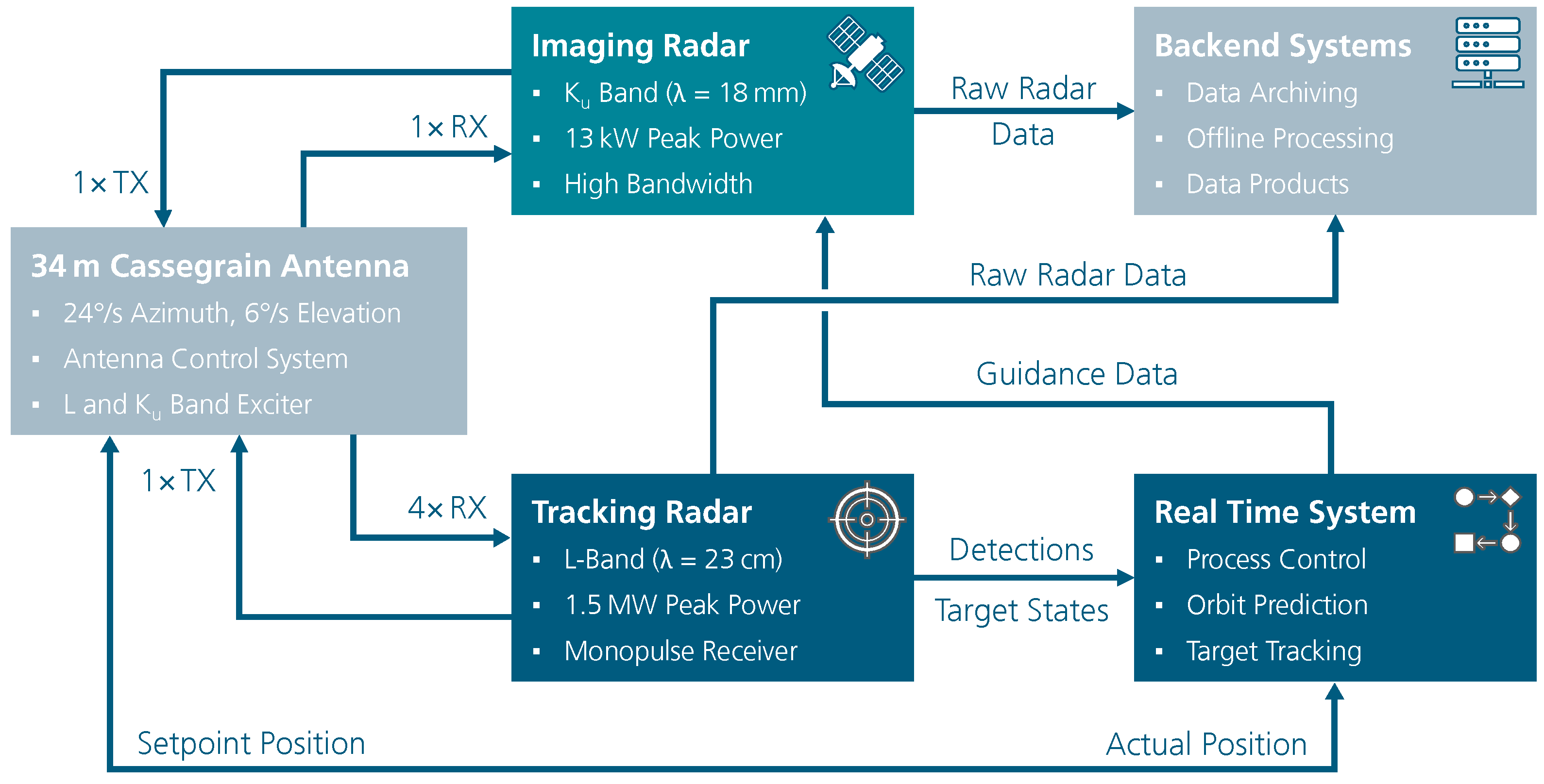
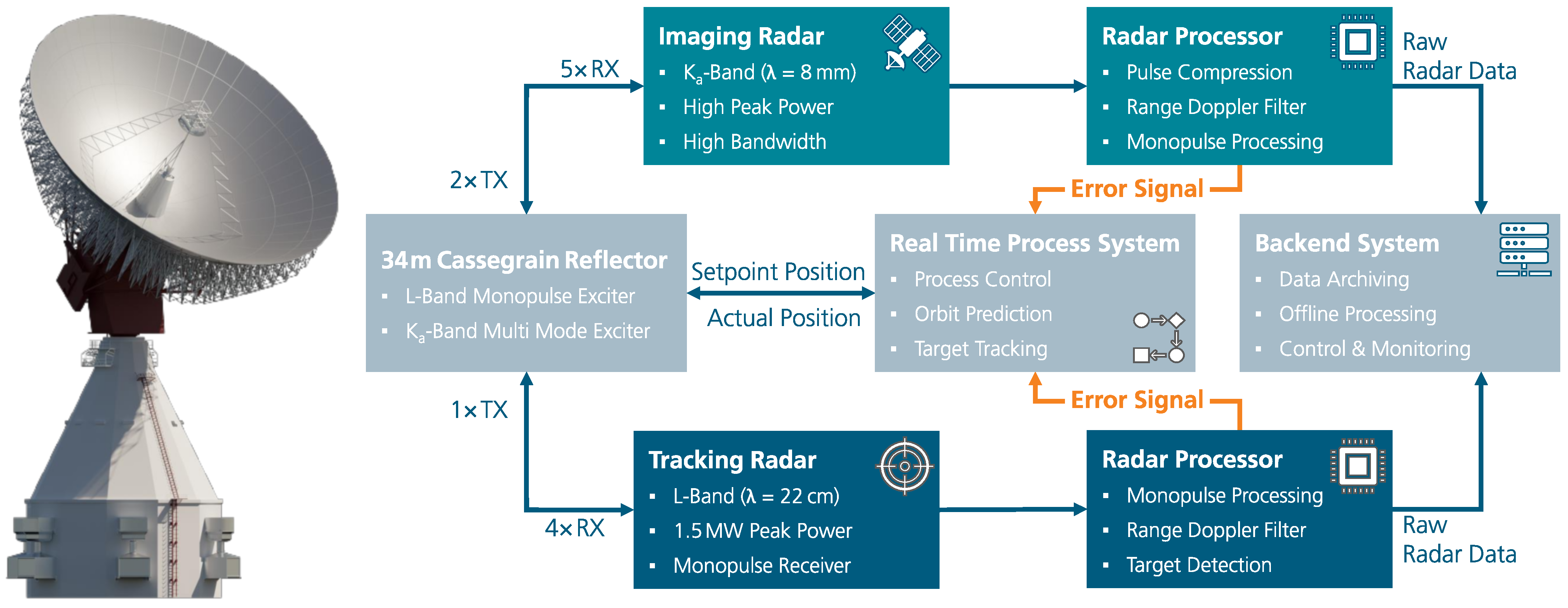
One of the world’s largest radar domes (radomes), visible from afar, is situated in Wachtberg near Bonn, Germany. The radome has a diameter of 47.5 m and protects the radar dish of the TIRA system from all weather influences (Figure 1). TIRA is one of the most powerful radar systems for space observation in Europe. Its three main components are the fully movable Cassegrain antenna system with a diameter of 34 m , the tracking radar in the L band and the imaging radar in the Ku band (Figure 2). The 240 t antenna structure rotates with up to 24 deg/ s in azimuth. This is necessary to track any artificial space object almost seamlessly, as tilting of the antenna above 90° in elevation is not possible. With this ability, the pass of a resident space object (RSO) can be observed without interruption close to its zenith. Note, that due to confidentiality, not all radar parameters may be listed in this paper.
Among the currently operating space radar systems, TIRA is recognized worldwide as a powerful weather-independent sensor for the observation of the near-Earth space environment [1,2]. For a comprehensive review of this field, see [3] and references therein. Recent advances are highlighted in the Special Issue at hand (Radar for Space Observation: Systems, Methods and Applications, a special issue of Remote Sensing https://www.mdpi.com/journal/remotesensing/special_issues/7C43H2J2V2, accessed on 29 October 2024). The development and construction of TIRA started by the end of the 1960s. As an experimental system, TIRA was modified and upgraded continuously over the decades. Its focus changed to space observation in the 1980s, followed by enhancing capabilities, e.g., to measure the space debris population in the 1990s or to increase the bandwidth of the imaging radar in the early 2000s. In addition, individual experiments like measurements on airplanes or jamming were conducted on the side. The latest upgrades were the implementation of a new antenna drive and control system in 2012 and the replacement of the tracking radar transmitter one year later. Finally, after 46 years of operation, the radome was renewed in 2014. For this, the new radome was constructed inside the old one up to a certain height, followed by taking off the cap and replacing it with the new cap, which was pre-assembled on the ground. At the end, the lower part of the old radome was dismantled, revealing the new radome step by step. The new radome consists of statistically distributed triangles with side lengths between 2.1 m and 4.5 m which ensures that interferences are minimized. A membrane between the aluminum rods allows the radar waves to pass through nearly undisturbed.
In its current configuration, TIRA is able to accurately determine RSO orbits while also generating detailed radar images of them [4,5,6,7]. In the following paragraphs, the present state of the system and its capabilities are introduced. Later, the plans for the complete overhaul of TIRA’s two radars are discussed in detail. This transformative system upgrade will be a game changer in space observation with radar.

1.1. Current Configuration of the Tracking Radar

The tracking radar operates in the L band in a frequency band around 1.3 GHz. Radar pulses are sent to space objects and received after reflection of the electromagnetic waves by the large radar antenna. Range, range rate, azimuth angle, elevation angle, and time are calculated from the radar echoes by using a monopulse system in order to estimate the orbits of the space objects with high precision. The tracking of space objects starts when they cross the horizon and stops just before they disappear below the horizon. For this, the tracking radar uses a monopulse system which consists of four horns for transmit and receive. The ratio of the sum channel to the respective difference channels is a measure of the deviation of the object direction from the antenna axis. This allows the antenna position to be continuously corrected so that space objects are always close to the center of the main lobe and can be precisely tracked. TIRA’s mechanical alignment accuracy corresponds to 3 m at a distance of 1000 km. Since the true object positions differ from the measured positions due to the refraction of the radar waves in the Earth’s atmosphere, the data are corrected after the measurement using recorded environmental parameters (e.g., temperature, atmospheric pressure, and humidity) with a suitable atmospheric model. The main lobe has a width of almost half a degree (about the diameter of the full moon), which corresponds to a lobe diameter of 8.6 km at a distance of 1000 km. Thanks to the high transmission power in combination with the large antenna area to achieve high sensitivity, even objects with a diameter of just a few centimeters can be detected, tracked, and measured at a distance of 1000 km.
For a standard RSO observation, the TIRA system uses a two-line-element (TLE) dataset to initially acquire and track a selected space object. The knowledge of the space object position can be more or less accurate, depending on different factors. As the orbit of a space object is affected by diverse forces, e.g., solar radiation pressure (SRP), atmospheric drag, and third-body attraction forces from the Moon and the Sun, the age of the TLE dataset plays a fundamental role. The largest deviation between the actual orbit and the propagated one using the TLE dataset is in the along-track direction. It can already be about 1 s (i.e., about 7 km to 8 km along-track distance in low Earth orbit (LEO)) for a one/two-day old TLE. The tracking method, which is currently implemented in the L-band radar, estimates the time offset (along-track) between the actual orbit of the space object and the one derived from the TLE dataset in real time. This time offset is then compensated continuously for each pulse to ensure that the object remains in the main lobe of the antenna beam. Without this correction, the object could be missed as the antenna lobe of the L-band radar at a range of 1000 km is 8.6 km.

1.2. Current Configuration of the Imaging Radar

The TIRA system also has a broadband, coherent imaging radar system which works in the Ku band with a center frequency of 16.7 GHz. It is always used when not only very precise orbit data are required, but also the imaging of a space object is needed.
This is the case, for instance, during a contingency support when a satellite is not behaving nominally, and a visual analysis is needed. Indeed, two-dimensional radar images can be used to detect mechanical damage to the satellite that may have been caused by a collision with space debris. If one processes 2D radar images one after the other over the whole flyover, one can even generate a radar video which shows the rotational motion of the satellite and eventually different sides of the object. From the radar image series, one can calculate the attitude motion of a satellite and assess a potential tumbling motion. Due to the higher frequency compared to the L-band tracking radar, the antenna lobe is significantly narrower with 0.031°, which corresponds to a lobe diameter of 540 m at a distance of 1000 km. Since only the L-band radar has a tracking capability, it is needed to steer the imaging radar. Due to the significantly narrower antenna lobe in the Ku band, the tracking radar must track space objects extremely precisely so that the Ku-band antenna lobe stays on the object.

2. Radar Techniques for Space Observation and Products

2.1. Generation of High-Quality Observation Vectors for Orbit Determination

The tracking radar of the TIRA system measures for each transmitted pulse the range of a space object as well as its range rate, azimuth angle, and elevation angle. The estimation accuracy of each measured parameter depends on its specific resolution and on the signal-to-noise ratio (SNR). It is well known that averaging over several measurements improves the estimation accuracy of a random variable. Indeed, the estimation accuracy is improved by a factor N when averaging over N realizations. The latter assumes that the process of the random variable is wide-sense stationary, i.e., the variance is finite, the expected value is time-invariant, and the autocovariance is translationally invariant.
However, for LEO objects, the different parameters strongly change over time due to the fast motion of these objects relative to the radar. Averaging over a large number of pulses is counterproductive as it deteriorates the estimates due to the underlying dynamics. This effect is examined in the framework of orbit determination [8] where a processing time of about 1 s is derived as a good compromise between improvement in the estimation accuracy and process stationarity.
As introduced in [6], a coherent processing over N subsequent pulses can be applied to increase the estimation accuracy of the range rate and to derive a new parameter, the range-rate rate (Figure 3c). The latter is determined independently of the aforementioned observables. This parameter is particularly interesting for initial orbit determination (IOD) [6]. Currently, the tracking radar uses a correlator quartet to determine the range and range rate of the object. This method works similarly to a monopulse system by comparing the outputs of the matched filter at different delays and Doppler frequencies. The major advantage of this method is its rapidity as it avoids a grid search to estimate the Doppler frequency. The price to pay is that the estimated values are slightly biased (Figure 3b, red dots). The bias is much more important than the center of the correlator quartet being shifted from the true object position in the range/Doppler plane. This solution was chosen in the past as the best tradeoff for a real-time implementation. It will be replaced by the realization of a matched filter bank in the future development stage of TIRA to obtain unbiased estimates and better control the residuals. The range rate bias can be corrected by the coherent integration filter [6] (Figure 3b, black dots). The refined range rate and the range-rate rate can be used to improve the range estimate (Figure 3a, black dots).
If the object was also observed with the imaging radar, a more accurate range could be determined from the imaging radar data. Indeed, the used bandwidth of the imaging radar is much larger compared to the one of the tracking radar, yielding a much finer range resolution. Since the imaging radar transmits chirp waveforms, a coupling between the range and the Doppler exists. This ambiguity has to be first solved in order to estimate accurately the range of the object [6] (Figure 3a, blue dots).
A high-quality observation vector at a given epoch can be derived, which regroups the new range estimate with the refined range rate, the range rate, and the angular parameters. The benefit and longevity of these highly accurate measurements for orbit determination and cataloging are currently under evaluation.

2.2. Separation of Multiple Objects

In certain situations, space objects are orbiting very closely to each other. This can happen, for example, during the release of satellites, during robotics missions, or during a spying attack. In this case, it is important to detect and monitor the maneuver from the ground and to estimate the distance between the objects. This can be achieved using the imaging radar. However, for the current imaging radar, the distance between the objects should be less than 100 m in range and 500 m in cross range at a range of 1000 k m . This strong constraint restricts the use of the imaging radar only to close proximity maneuvers. It is worth mentioning that if the range/Doppler histories of the objects differ from each other, the objects cannot be all focused simultaneously. Indeed, different processing filters are required to image the objects. Depending on the processing, one of the objects will be sharply imaged, while all the others will be blurred.
It is possible to discriminate objects with the tracking radar without the use of radar imaging. Even if space objects are located jointly in the antenna beam and in the same range/Doppler resolution cell after matched filtering, coherent processing can be applied to the multi-channel data acquired by the monopulse system in order to discriminate the objects in the 4D space range rate/range-rate rate (the rate of change of the range rate)/azimuth angle/elevation angle. The separation in angle can be achieved, e.g., by using the monopulse dechirping method [6], which is an extension of the method presented in [9].
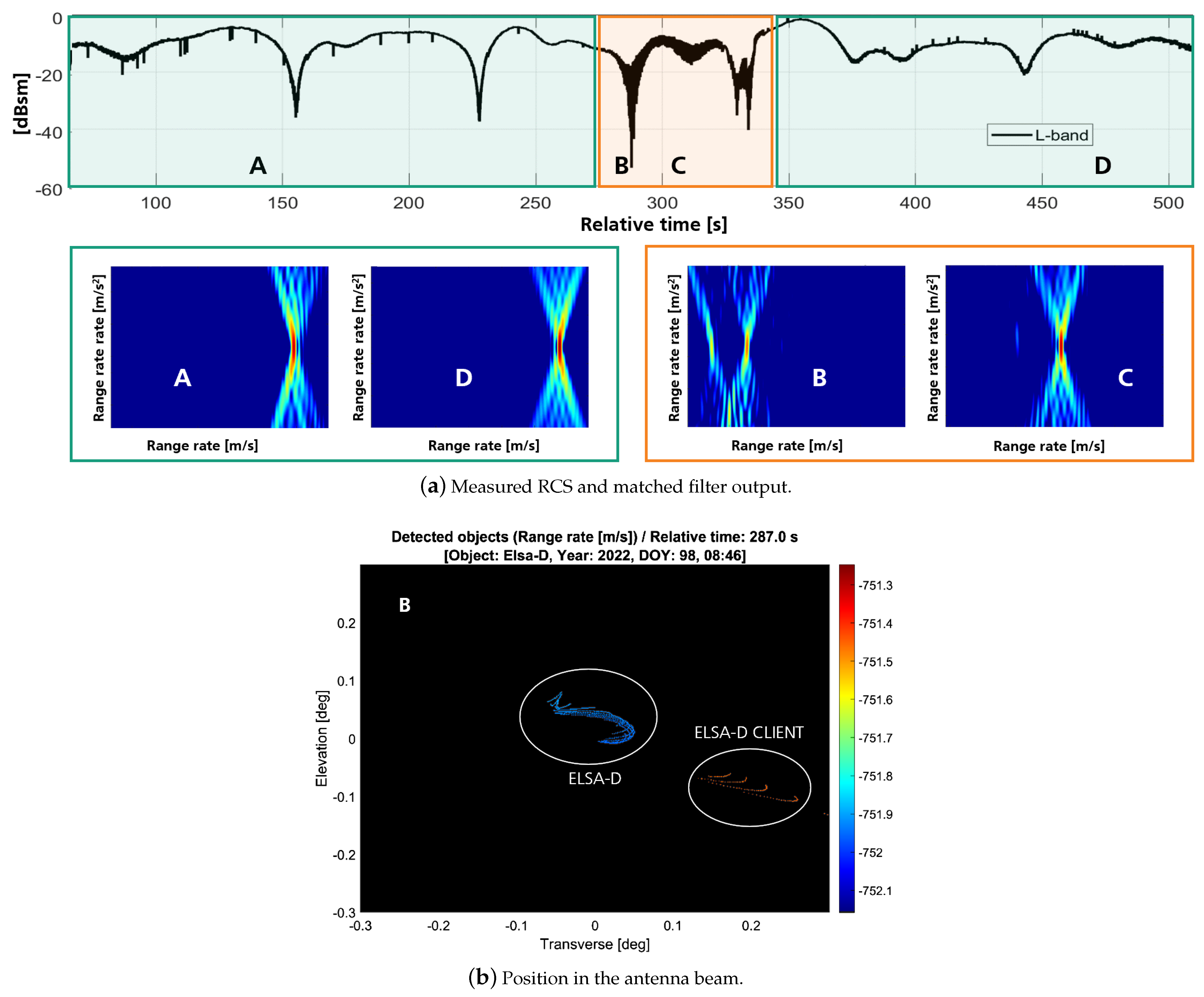
This multi-channel coherent processing can be applied to discriminate objects in different orbital regimes. The example of an Astroscale exercise [10] during which an encounter maneuver was performed between two LEO objects, ELSA-D (larger object), and ELSA-D CLIENT (smaller object, see Figure 4), is shown in Figure 5. Figure 5 plots the measured radar cross section (RCS). During a limited time, both objects were located in the same radar beam. This corresponds to the region indicated by the orange box in Figure 5, which presents an oscillating pattern revealing the presence of several close objects. Applying coherent processing enables us to identify both objects (e.g., at time B and C), whereas only one object can be detected in the green regions (e.g., at time A and D). The right picture shows the relative location of the two objects in the antenna beam after monopulse dechirping processing. It has to be noted here that the TIRA system uses an amplitude monopulse to estimate the angular position. Contrary to a phase processing, it is not possible to correct for the object motion within the antenna beam during the integration time. The fast object motion in LEO, the required beam tracking, and the variation in the relative position of the object within the antenna beam cause an amplitude modulation in the received signals affecting the estimation of the angular position. Nevertheless, the relative position of the objects in the antenna beam can be coarsely followed over time.
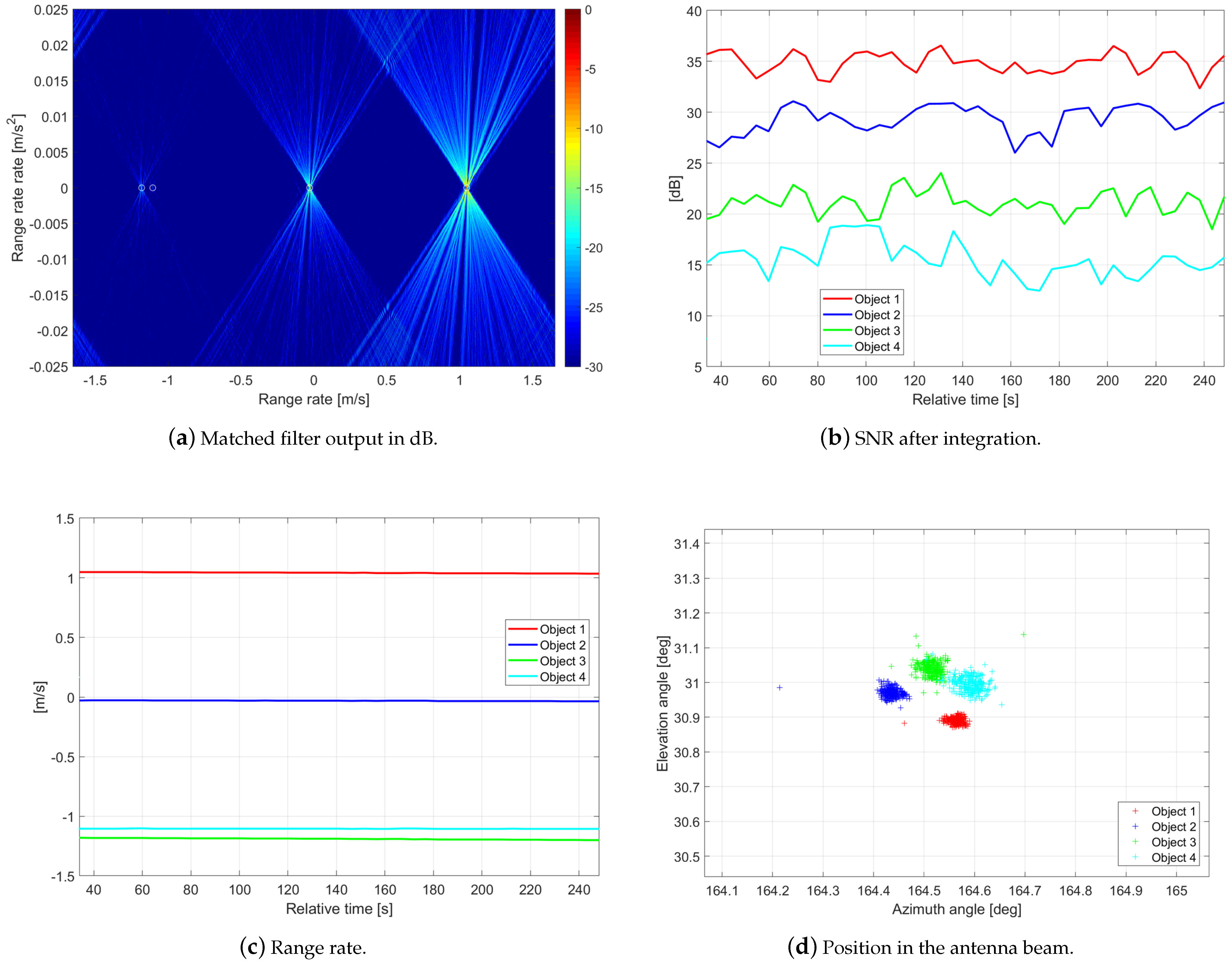
The same type of processing can be applied to the geosynchronous equatorial orbit (GEO) orbital regime. One major difference is that the single pulse SNR is so low that space objects cannot be directly detected. Integrating over several pulses is mandatory for target detection. GEO objects orbit at the same angular velocity as the Earth. They thus appear to be stationary for an observer on the Earth and their location in the antenna beam is fixed. Figure 6 shows the results of an observation of the NILESAT cluster. All four satellites could be successfully detected, and their parameters estimated.

2.3. Radar Imaging of Space Objects

Different focusing techniques can be used to image space objects. The choice of the method depends on the bandwidth of the transmitted radar waveform, on the attitude motion of the object (i.e., slow or fast rotating), and on the spanned k-space. Conditioned by these parameters, either a fully coherent, a partially coherent, or an incoherent processing is possible. The basic prerequisite of all these reconstruction techniques is similar, as they exploit the variation in the aspect angle between the space object and the radar during the data acquisition to image the object. This variation leads to a change in the Doppler frequency over time. For all these methods, the spatial resolutions achieved in both image dimensions are independent of the object range. This is a main advantage compared to optical systems.
The major challenge of radar imaging for space observation is the accurate estimation of the translational and rotational motion of the object. Indeed, the knowledge of the object kinematic is a prerequisite to form sharp images of the rotating space object. This dynamic information has to be estimated directly from the radar data as space objects are uncooperative targets, meaning that accurate enough information about their attitude motion and positions (requiring cm/mm-precise ephemerides depending on the center frequency used) is not available. During the processing time required to compute a radar image, the rotation vector should be constant. Otherwise, the imaging plane varies, and the radar images are distorted.

2.3.1. Imaging with the Ku-Band Wideband Radar

Inverse synthetic aperture radar (ISAR) is a fully coherent processing method, which is the most commonly used technique to produce high-resolution images of rotating objects [12]. It is particularly adapted to intermediate tumblers. A fine resolution in range is achieved with a large signal bandwidth. In order to separate backscatterers in cross range, a spectral analysis is performed on the range profiles acquired over consecutive pulses. The cross-range scaling of the ISAR image is set by the effective angular velocity of the space object. The integration time is usually chosen to obtain similar resolutions in range and cross range.
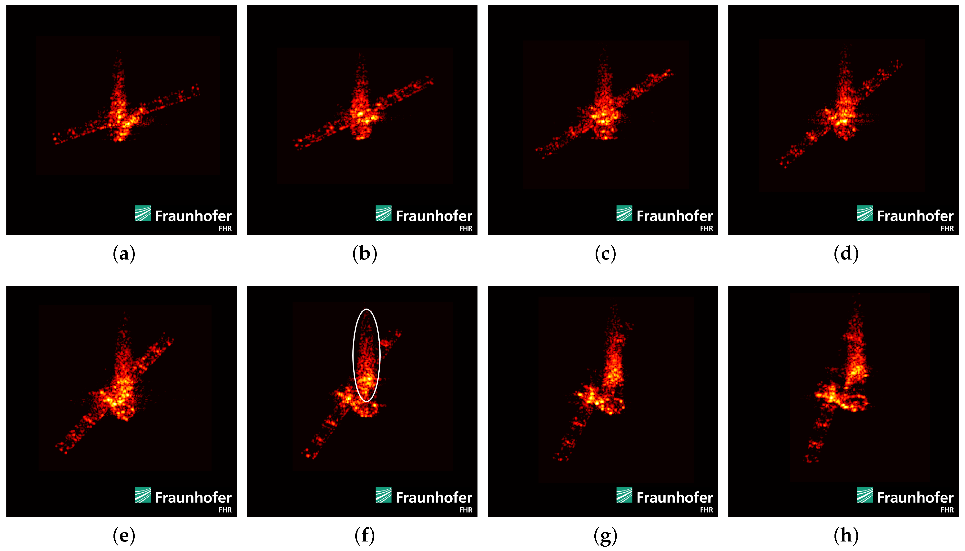
To illustrate the efficiency of the ISAR technique, Figure 7 shows the last ISAR image series of the European Space Agency (ESA)’s satellite AEOLUS before its re-entry. The time between two consecutive radar images is about 6 s . The effect of the rotational motion of the object is particularly visible in the image sequence. The different parts of the satellite (e.g., main body, solar panels) can be clearly identified. The reflections in the center part (see, e.g., the marked region with an ellipse in Figure 7f) are not caused by a system artifact but by the multiple reflections of the radar waves in the instrument payload Aladin (range extended returns).
Due to the limited pulse repetition frequency (PRF), the raw data of fast rotating objects might be under-sampled. This violation of the Nyquist condition affects the signal phase over slow time (aliasing effect). As a result, the radar image processed with the ISAR principle is the superposition of the true image of the object (unambiguous signal part) with its ghost images (ambiguous signal parts). The distance between the unambiguous and ambiguous images depends on the rotational motion of the object. For high angular velocities, all the images are overlapping, and the object cannot be imaged properly. To illustrate this effect, Figure 8 shows an ISAR image of Jason-2. The apparent angular velocity was estimated to be about 9 deg/ s . The additional solar panels at the edge of the image can be clearly identified as ghost images.
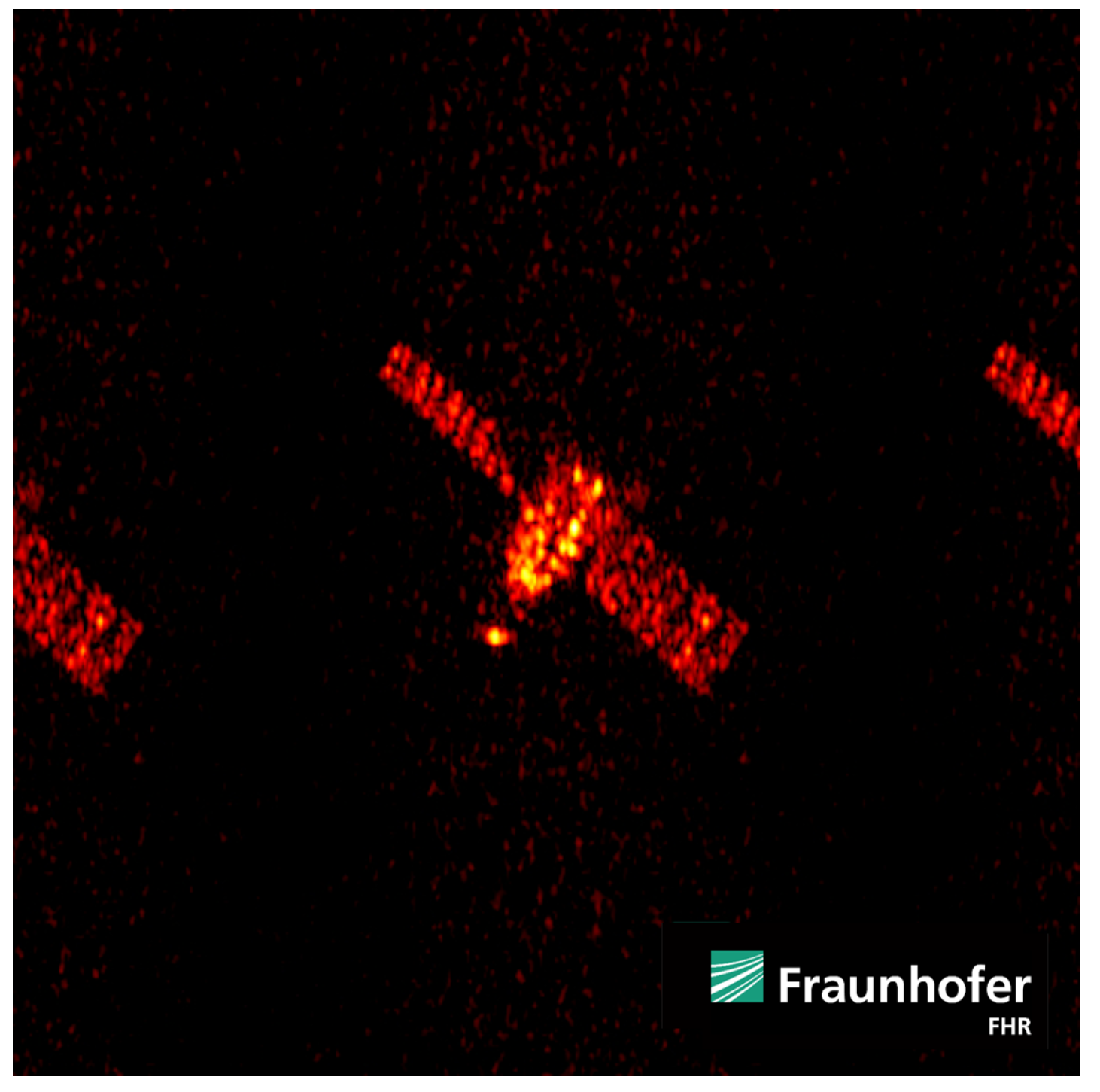
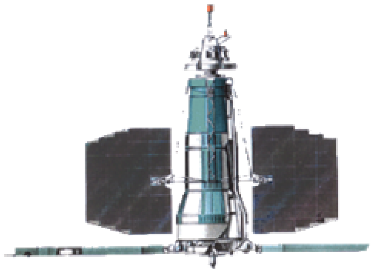
The radar data of fast tumblers can be processed using the same tomographic approach that is used for medical imaging [14]. The tomography technique exploits the amplitude values of the range profiles over time. The achievable resolution depends on the transmitted signal bandwidth and on the covered aspect angle. The Russian satellite COSMOS-1408 is taken as example in the following. This satellite was hit by a Russian anti-satellite (ASAT) weapon in November 2021 [15]. The largest debris piece of the generated fragmentation cloud was observed with the TIRA system two weeks after the event. From the range profiles presented in Figure 9 [15], an apparent angular velocity of about 90 deg/ s could be extracted. Because of the strong under-sampling, meaningful ISAR images could not be computed. Figure 9 shows a radar image generated with the tomographic approach. The figure reveals that the solar panels, the gravitational boom, and the signals intelligence antennas were destroyed by the ASAT weapon. Only a solar panel attachment is still visible in Figure 9 when comparing it with Figure 10. Radar images computed with tomography differ from the ones computed with ISAR. The longer integration time raises the requirement on the range profile alignment and on the stability of the rotational vector. Temporal variation in the angular velocity causes a smearing of the radar images and should be accounted for. This is also true for ISAR; however, it is less critical due to the shorter processing interval.

2.3.2. Imaging with the L-Band Narrowband Radar

Recent work has demonstrated the possibility of imaging with the narrowband tracking radar of the TIRA system [17]. Again, the angular velocity of the object is a key parameter for imaging, as it determines the integration time and the sampling positions. Different techniques can be applied.
The first method is a partially coherent processing. It exploits the micro-Doppler signature of the space object using a tomographic approach. This Doppler tomography technique was presented in [17] and applied to the monostatic and bistatic radar data of an Atlas-5 Centaur rocket body orbiting in the medium Earth orbit (MEO) region. The spatial resolution is a function of the PRF, the angular velocity, and the used radar wavelength. Figure 11a shows a Doppler tomography image [17] of the rocket body including a zoom of its upper part. The shape of the object is clearly recognizable. The radar waves were not backscattered by the center part of the rocket body towards the radar, explaining the dark area in the center of the radar image, except for a small region corresponding to the reflection off of a cable duct.
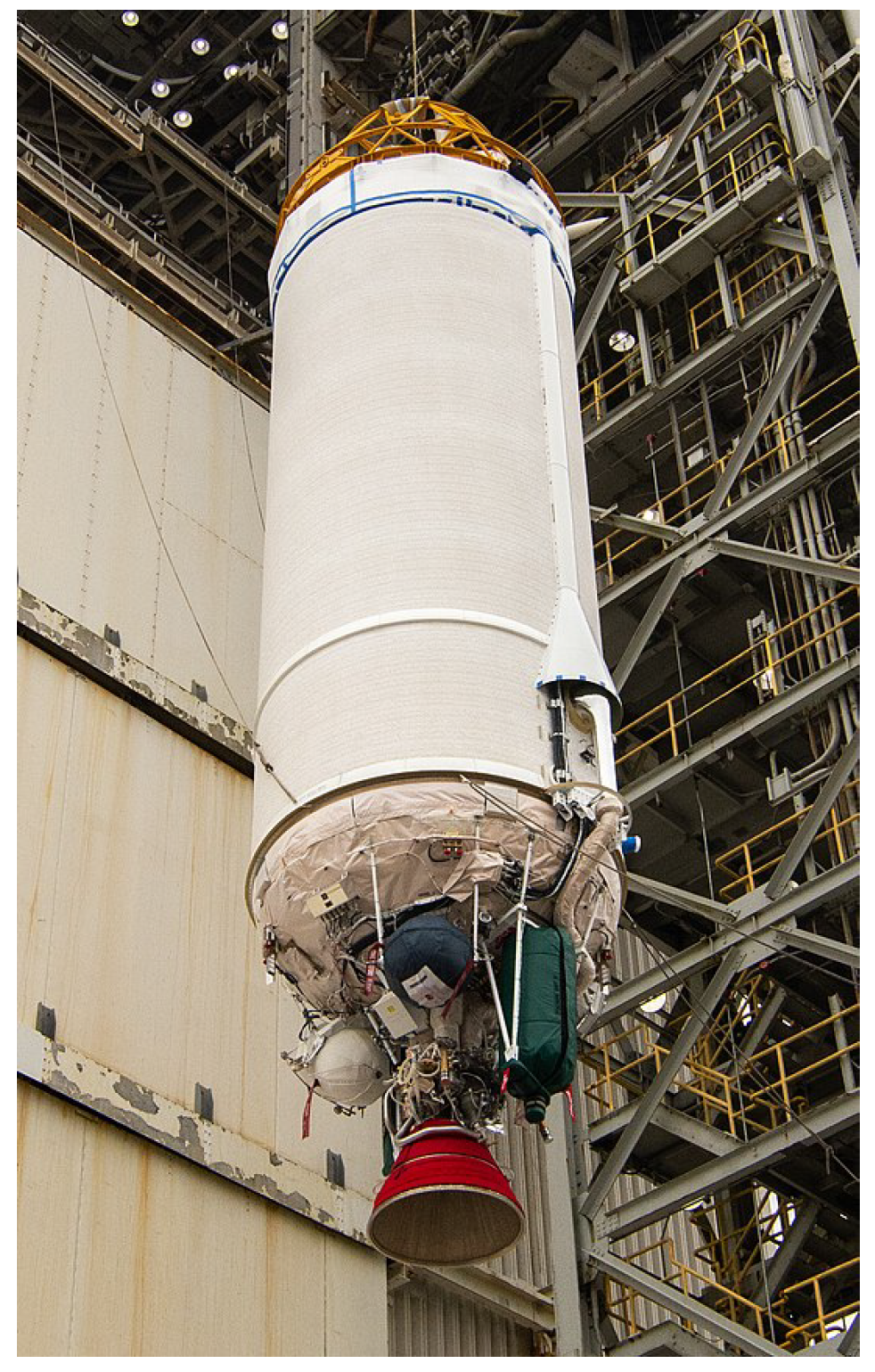
The data can be also fully coherently processed similar to the ISAR reconstruction using a larger aperture angle [17]. The minimum achievable resolution is given by a quarter of the used wavelength. This processing technique can also be applied to the data of the imaging radar. Figure 11b presents the reconstructed radar image using a back-projection algorithm [17]. The resolution is finer compared to the Doppler tomographic reconstruction at the cost of high side lobes. Fine structures of the object are visible in the zoom area, in particular the structured pattern of the adapter ring (see Figure 12). To better analyze the object, a composite image merging the results of both reconstruction methods can be generated using different thresholds for imaging, as presented in Figure 11c.

3. Challenges for a Future Imaging Radar for Space Observation

3.1. Future Situation in Earth Orbit

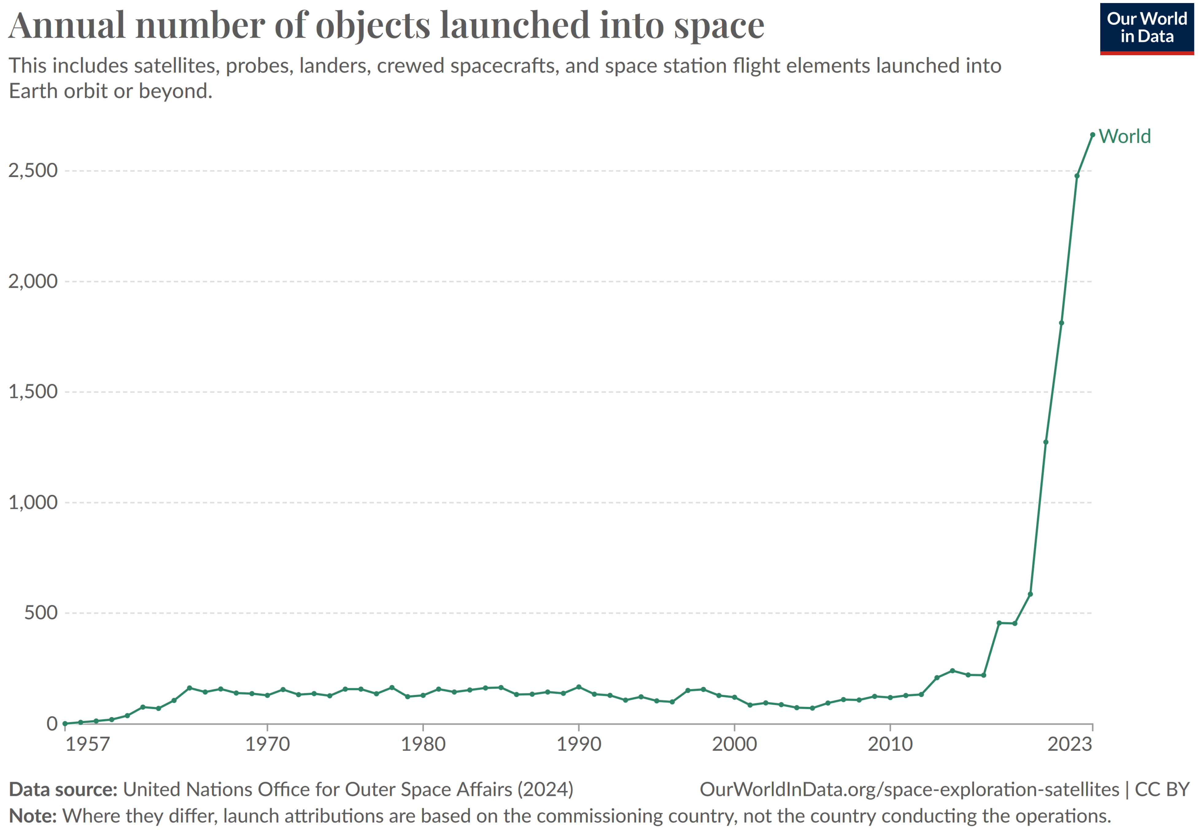
The use of near-Earth space has grown drastically since the first artificial satellite Sputnik was launched in 1957. Sixty years later, the annual number of launched objects is raising exponentially (see Figure 13). As of 2024, more than 19,000 satellites have been placed into Earth orbit [19]. In addition, there is a constantly increasing amount of space debris. It is estimated that around 4500 objects orbiting Earth are larger than 10 cm, around 1,100,000 objects between 1 cm and 10 cm, and around 130 million objects between 1 mm and 1 cm, as of August 2024 [19]. The amount of space debris is constantly rising due to debris breaking apart, explosions of spent rocket stages and collisions of debris between each other or from debris with satellites. When two space objects collide, thousands of new pieces of debris can be created. This is what happened, for instance in 2009, when the defunct Russian military satellite Cosmos-2251 collided with the communications satellite Iridium-33. Many thousands of new pieces of space debris were detected. This large amount of space debris around Earth is a significant threat to all active satellites as any collision can damage or completely destroy a satellite generating even more debris.
In recent years, so-called mega constellations have also been launched. In each of these constellations, thousands of small satellites are placed into orbit. The growing object density increases the overall collision probability, as any of these satellites can collide with each other or with space debris, creating a new cloud of debris.
Finally, every active satellite becomes space debris at the end of its life if not actively de-orbited, or even earlier in the event of a failure. In this case the defunct satellite stays as debris until it re-enters in the Earth’s atmosphere after spending many years in orbit or until the satellite is taken out of orbit using special de-orbiting missions [7].

3.2. The Motivation for Ground-Based High-Resolution Fully Polarimetric Space Imaging Systems

One driver of change in the near-Earth orbit is the rapid progress in the development of new technologies. In the past decades, large, complex and very expensive monolithic individual satellites were built. Currently, the trend is towards the deployment of small and cost-effective systems. The trend towards constellations of small, less expensive, and simple satellites replacing large satellites allows for much shorter development and deployment times. Also, a better global coverage can be achieved with a constellation of small satellites. This development is also supported by standardized satellite buses and falling costs for satellite launches by private companies such as SpaceX. Inevitably, the amount of space debris will increase considerably in the near future, as small satellites do not have a long operational lifetime and are usually not equipped with an active or passive de-orbiting system. This trend is accelerated by the deployment of mega-constellations. For instance, Starlink satellites for global internet access might reach 12,000 objects in 2025. In addition, the reliability and thus the operational safety of these small satellites are also expected to decrease. This raises the risk of collisions with other space objects.
The trend towards smaller satellites poses a great challenge to ground-based reconnaissance systems. Moreover, the mountings and instruments are also becoming more compact for large satellites, so that their ground-based reconnaissance is also becoming increasingly difficult. This problem is heightened by the fact that some satellites have to be operated at significantly higher orbits. One reason is that LEO is already extremely populated at altitudes between 500 km and 800 km. Another reason is that it is often not possible to raise the orbit of small satellites when the orbit height decreases because of friction in the atmosphere.
Due to the future development of artificial satellites in near-Earth space described above, the reconnaissance capability of ground-based sensors has to be improved to meet the requirements of future reconnaissance systems. Future ground-based space reconnaissance systems must operate with a significantly higher spatial and radiometric resolution in order to be able to image small satellites at a far range together with their instruments and small attachments in order to perform technical analyses.
Additional information about space objects can be gained by using polarimetric ISAR. Especially in the case of a fully polarimetric space radar, the full electromagnetic vector field is available as opposed to a single polarized ISAR image. Fully polarimetric radar imaging takes advantage of illuminating objects with both horizontally (H) and vertically (V) oriented electric field vectors and also record both polarized returns. This acquires all four components of the scattering matrix and allows us to investigate the structure of space objects due to the interaction with the polarized electromagnetic waves [21].
Indeed, depending on the transmitted and received polarization directions, structures (e.g., bars) of an object might be clearly visible in the radar image or suppressed. This allows us to separate different areas or components of a space object in radar images in order to investigate them independently of each other in more detail. Moreover, very bright and prominent scatterers which outshine faint nearby structures could be suppressed to make adjacent faint scatterers visible.
A well-known consequence for ISAR imaging is the layover effect. This means that spatially separated resolution cells of a 3D space object can superimpose in the processed 2D radar image. As a result, the interpretation of 2D radar images of a space object might be difficult, since scatterers which physically and spatially do not belong to each other appear at the same image position. Polarized radar images might help to solve this problem by separating these superimposed pixels in different polarization directions.
Another prominent effect in imaging space objects is the occurrence of multipath reflections, e.g., from the satellite body itself or from mountings like optics of cameras. For instance, single or double reflections appear in different polarization regimes.
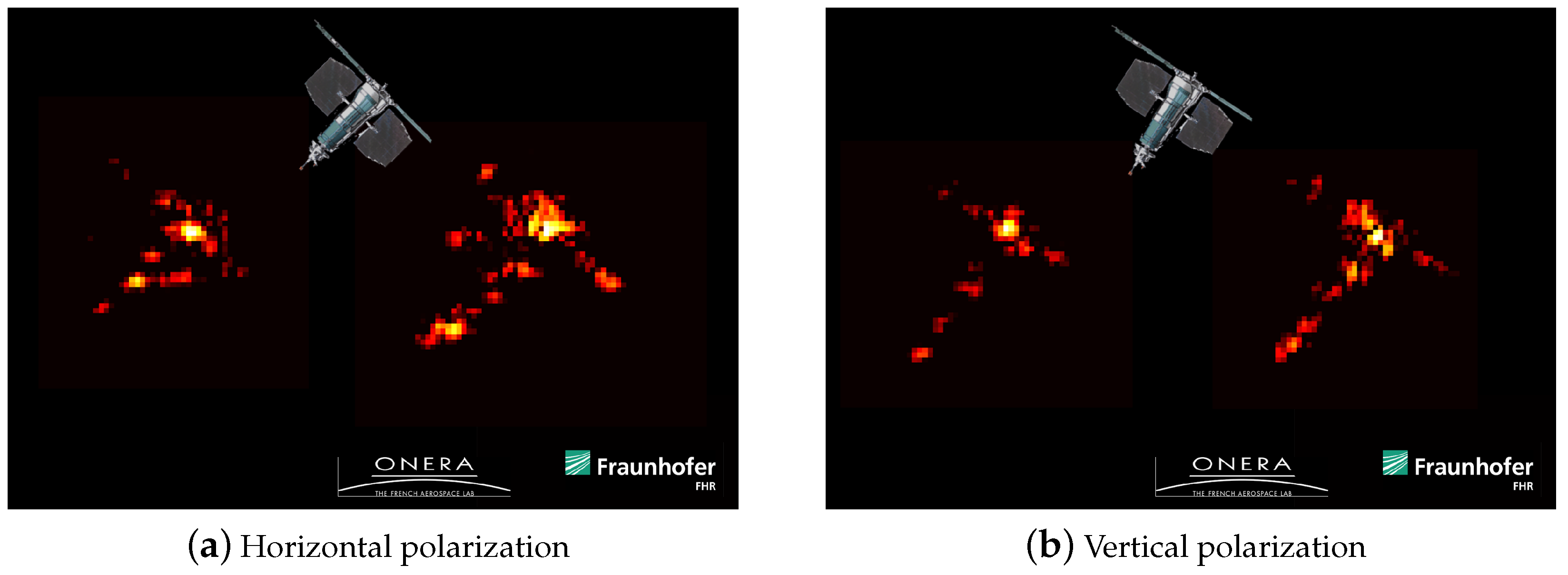
Figure 14 shows exemplarily a space object which was observed in a bistatic polarized configuration by the Office national d’études et de recherches aérospatiales (ONERA) and Fraunhofer Institute for High Frequency Physics and Radar Techniques (FHR). One sees very clearly that different regions are prominently visible in both polarizations. This helps to investigate and to interpret the radar image much better than with just a single polarized ISAR image.

4. New TIRA System Design

With the currently ongoing upgrades, the TIRA system is facing a major overhaul concerning both radar instruments and the complete process control infrastructure. This extensive endeavor offers the unique opportunity to design a new overall system architecture. This architecture, conceptualized to be modular and open, will enable continuous incremental upgrades of TIRA in the future. During the current phase, one key is the utilization of commercial off-the-shelf (COTS) components adapted to and interacting via robust interfaces. Figure 15 shows the prospective system architecture after completion of the major upgrades to the radar subsystems. These upgrades will enhance TIRA’s capabilities as a research instrument and meet the increased requirements emerging in the context of space situational awareness (SSA).
The future system is composed of three main subsystems: the fully movable parabolic antenna, the high-power L band radar, and the broadband imaging radar in the Ka band. A key point in the new architecture is to enable the Ka band imaging radar to track space objects in addition to the tracking capabilities of the primary tracking radar in the L band. The overall process control will be implemented as a distributed real-time system with emphasis on composability, scalability, and dependability. Real-time control of subsystems is localized as needed to achieve fast response times and autonomous subsystem functionality along parameters is defined and continuously updated by higher systems. Both radars and the antenna infrastructure are controlled by a central real-time processing system.
This system handles orbit prediction and target tracking and automates standard measurement scenarios, while extensive customization allows users to conduct specialized experiments. Data storage and offline processing of the radar data are handled on common back-end systems. These also aggregate and record monitoring data sent by the various subsystems to maintain an overall picture of past and current system status and health.

4.1. Model-Based System Engineering

To cope with the complexity of the future TIRA system during design, realization, and also operation, it was decided to apply methods from the field of systems engineering, particularly model-based system engineering (MBSE). The specific method and tooling used was the ARChitecture Analysis and Design Integrated Approach (ARCADIA) [22] along with the Capella open-source modeling software.
Figure 16 summarizes the principle of the ARCADIA method. The development process starts with the operational analysis evaluating the needs of the users focusing on the system. The view is then reversed in the functional analysis providing what the system has to accomplish for these users. Following these analyses, the architectural design is first considered in the logical architecture layer, which refines the system’s functions and allocates these functions to local components. Finally, the development cycle leads to the physical architecture and the respective component specifications.
In addition to this structured development, MBSE also facilitates documentation of the requirements, here denoted as R-*, system design, and the system itself. These requirements are traceable from operational analysis to the physical architecture, thus consequences of design changes can be easily assessed.
This approach, if consequently applied, will lead to a well-defined system architecture with consistent interfaces to obtain an extensible research system adaptable to new requirements.

4.2. System Monitoring

Monitoring system health and status permanently is important to maintain high availability. It further gives crucial information in case of repair and maintenance. This includes system health parameters such as device temperature, voltages and currents, application parameters like encoder values of the rotating axes, set and error values of the antenna controller and meteorological measurements like air temperature/humidity and liquid water content to estimate the signal propagation parameters like the zenith tropospheric delay.
Every module reports environmental and system parameters via a network to a time series database (InfluxDB, open-source, MIT license, https://www.influxdata.com/ accessed on 29 October 2024). This solution enables us to analyze a high-rate time series of measurements with high performance and presents the result on a configurable dashboard system (Grafana, open-source, AGPLv3 license, https://grafana.com/, accessed on 29 October 2024) in real time. Collecting a high-rate time series requires high storage capacity and slows down the querying and processing of such kinds of data. Time series databases are designed to overcome this drawback by rule-based aggregation of the high-rate data using statistical downsampling methods and fast compression algorithms to reduce data size and query time.
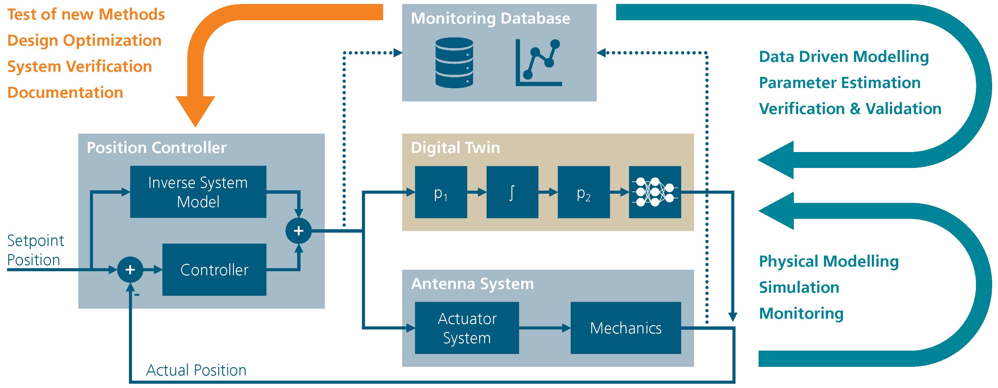
Alongside MBSE, we also aim to develop a comprehensive digital twin of our radar system. The basic concepts are shown in Figure 17 by the example of the antenna’s positional control system. The digital twin can be based on physical models with parameters estimated from monitoring data or even black-box models. New positional controller designs, for example, can be tested and optimized on the digital twin, before they are implemented on the real system. Having a complete system model, new methods of space observation can be developed with the digital twin before applying them on the real system.
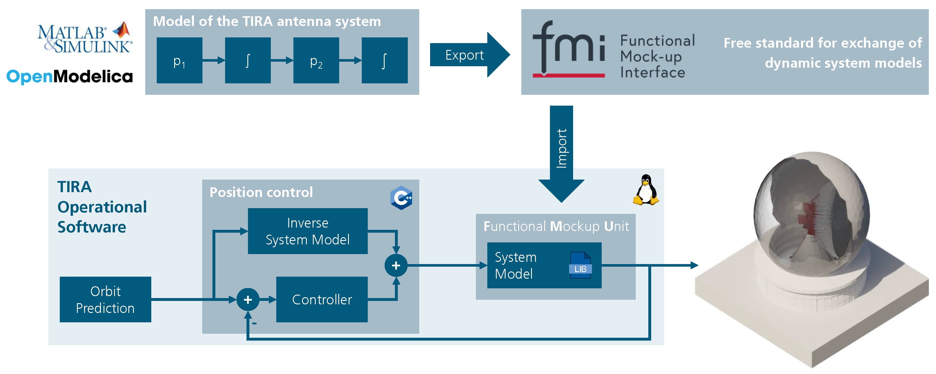
To not be tied to a specific modeling tool, the open Functional Mock-up Interface (FMI) standard is used to integrate simulation models into the system as illustrated in Figure 18. Such models can be exported from both open-source and commercial modeling tools.

4.3. Software Architecture

With TIRA being an experimental system, it is expected that parts of the monitoring and control software will be modified frequently. It must be possible to adapt or replace individual software components without affecting the entire system. In particular, changes in one component must not impair the proper functioning of other components. This requires well-defined interfaces and good isolation between the software components. These requirements lead to a microservice-based architecture, which also integrates well with the distributed nature of the various control, monitoring, and signal processing components.
The communication between the services uses the ZeroMQ messaging library and the Protocol Buffers’ data serialization format. ZeroMQ offers a high degree of flexibility in the design of the communication architecture, while Protocol Buffers implements an efficient and compact format for structured data. Both technologies are well established and have previously been used in the context of large steerable antennas and telescopes [23,24]. To ensure that the service interfaces are well defined, they are specified using a combination of the Protocol Buffers interface description language and a custom, YAML-based format.

4.4. Access to the Global Reference Frame and Time Scale

The radar measurements of the TIRA instruments are acquired in their native coordinates given by signal delay and Doppler frequency or (pseudo)-range and range rate, respectively, and the monopulse direction of arrival (DOA) estimates of the targets echoes. Besides these measurements, the azimuth and elevation of the mechanical pointing as axis positions of the reflector are logged by the antenna positioning system.
On the other hand, the targets’ motion, usually that of space objects, have to be modeled in a global inertial reference system like the International Celestial Reference System (ICRS). To obtain the measurements in the respective ICRS realization, the International Celestial Reference Frame (ICRF), we have to transform the acquired data with the help of auxiliary measurements and through intermediate systems.
TIRA maintains a local time scale operating a cesium beam primary clock to which timestamps and frequencies of the system are tied to give coherent measurements. This local time is attached to coordinated universal time (UTC) via common-view GNSS time transfer or precise point positioning (PPP). As the local clock is clocking a time-transfer global navigation satellite system (GNSS) receiver in the same setup as that maintained by metrology institutions, we can directly tie the local time scale to the UTC (PTB) which is realized in Braunschweig by jointly processing the GNSS raw data of both stations.
Measurements of the radar are given in their respective feed’s fixed coordinate frames. The measured propagation time is represented as pseudo-range and referenced to the intersection of the antenna rotational axes. Doppler frequencies are interpreted as range rates. To obtain the geometric range of the target, multiple effects of signal propagation, for example, from special relativity, troposphere, and ionosphere, have to be taken into account. The estimation of the respective models is supported by a meteorological measurement as well as observations of the GNSS permanent station. The monopulse system is calibrated and aligned along with measurements of the one-way and two-way antenna patterns using a terrestrial remote station at a distance of 23 k m . Further calibration and validation are established through the in-orbit measurement of suitable objects with known precise ephemerides.
The derived target position in the feed’s coordinate system is then transformed to the antenna coordinates with knowledge of the reflectors’ pointing vector. In order to access this vector, the mechanical boresight reference of the antenna is given by an optical mirror which was used to align the parabolic reflector panels during initial setup. The orientation of that mirror and thus the pointing of the antenna is measured by encoders on the axes. Measurements on the elevation angles are referenced to the local tangent plane by autocollimation with an automatic level towards the reference mirror; the azimuth encoders are referenced by transferring the normal of the reference mirror to a theodolite on the north monument outside the radome structure via collimation, which then measures the horizontal angle towards a marker on the GNSS station. As this baseline is known by astronomical optical measurements, a direct relation between the azimuth reading and true north is established.
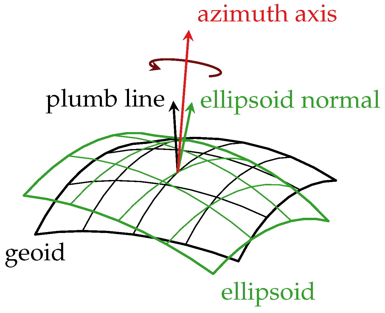
As indicated in Figure 19, three vectors are involved to find the relation between the reflector system and the global terrestrial system. The true orientation of the azimuth axis, the local vertical as normal to the geoid, which is accessed by leveling, and the normal to the ellipsoid as reference in the global system. The deviation between the axis and the local vertical is determined by measurement, while the so-called deflection of the vertical between the reference surface normals are evaluated from the geoid model.
Although the axes of the antenna were aligned to the local vertical or plumb line during construction, the azimuth axis tilted during the first decades, probably due to settlement.
Figure 20 shows the history [25] of the measured deviation of the azimuth axis from the true vertical. The symbol δ denotes the magnitude of the angular deviation in arcseconds, δ N and δ E give its components in the north and east direction, respectively. Until recently, the measurement was performed using an automatic level in combination with a parallel plate micrometer observing the vertical movement of a point fixed to the turning azimuth platform over a full revolution. The amplitude and phase of that sinusoidal quantity along the azimuth angle then gave the magnitude and direction of the axis deviation.
Today, this deviation is regularly monitored using a high-performance accelerometer with a noise density of 2 μ m   s 2   Hz 0.5 . Mounted near the center of the azimuth rotation, it directly observes the precession of the vector of gravity, yielding measurements with arcsecond accuracy.
The deflection of the vertical is estimated as a gradient of the German Combined Quasigeoid (GCG2016), yielding ξ = 5.35 in the north–south direction and η = 1.13 in the west–east direction, respectively. These values are in good agreement with evaluations by ICGEM [26] using the global EIGEN-6C4 model to degree 2190 giving ξ = 5.04 and η = 1.42 .
As the target positions are now available in local tangent plane coordinates on the reference ellipsoid of the International Terrestrial Reference Frame (ITRF), they can be directly converted to Cartesian coordinates. The origin of the local tangent plane system is maintained by GNSS-PPP and monitored by GNSS–real-time kinematics (RTK) to the nearest SAPOS station. To estimate satellite positions from measurements in the local system, tidal effects at the ground have to be taken into account to compute the instantaneous station position. Utilizing the Earth rotation parameters (ERPs), these positions [27] may be transformed finally to the inertial ICRF.

5. Tracking Radar

The combination of the dynamic antenna and highly sensitive tracking radar in the L band enables unique capabilities for detection, discrimination, and orbit determination of space objects from the low Earth orbit (LEO) to geosynchronous orbit (GSO) regime. A new signal processing system based on the software-defined radio principle is being developed for the tracking radar to utilize the full potential of the system in meeting future requirements originating from scientific questions relating to space situational awareness.
The resulting system architecture is illustrated in Figure 21. By placing the analog-to-digital boundary as far as possible towards the radio frequency (RF) front end of the radar, all further signal processing steps can be defined in software. In this flexible approach, a modular software architecture enables these processing steps to be replaceable and swappable in the future to expand the implementation for new applications and research.

5.1. Early Digitization

One key aspect in the design of the new tracking radar is the early conversion of the RF signal into a discrete signal vector for further processing. This software-defined radar approach allows us to flexibly test novel signal processing algorithms in the real-time environment of radar target tracking. For this purpose, the RF signal is sampled directly in the bandpass domain.
To reduce costs and development time, COTS components are procured and customized to our needs. Two synchronized two-channel ADQ32 digitizer systems from Teledyne SPDevices are used to sample the four channels of the monopulse system in the second Nyquist zone. This system converts the signal to baseband by digital down-conversion (DDC). The following signal processing steps are performed on a graphical processing unit (GPU) to meet real-time requirements for the closed-loop tracking of targets.
As the signal is sampled directly after the receiver protection and the low-noise signal amplification module, the demanding environment of the module location on the moving part behind the apex of the antenna paraboloid (red platform in Figure 1) requires modifications to the cooling concept of the COTS signal conversion module, which was built for a regular workstation computer in a controlled lab environment. This module is integrated to an edge computing device developed by DELL, which itself is housed in a custom-designed 19-inch rack shelter.

5.2. Real-Time Radar Processor

The recording system allows continuous recording of the received signal. The current processing concept features a target acquisition channel searching in a wide range-Doppler band for semi-blind target recognition by Doppler variant pulse compression, as well as several narrowband tracking channels on the sum channel of the monopulse system. This enables multiple target detection and tracking.
For each detected target, a DOA-estimation using the monopulse ratio after evaluating the prompt sample of the monopulse receiving channels can be calculated to estimate range, Doppler, azimuth and elevation angles as observations for further processing in a tracking filter.

6. Imaging Radar

To meet the challenges of the future space situation with more and smaller satellites, it is desirable to improve the system’s capabilities to image these satellites. Therefore, the imaging radar’s resolution in the range and cross-range direction will be enhanced by increasing the bandwidth and center frequency, respectively. Due to the higher frequency compared to the current imaging system, a higher atmospheric attenuation is expected.
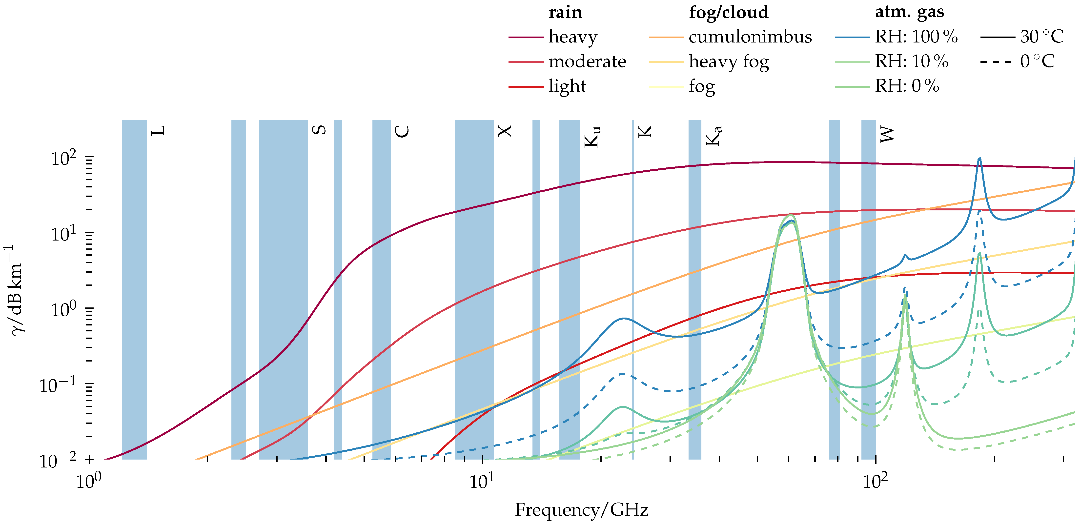
Figure 22 shows the attenuating effect of different atmospheric phenomena, like precipitation, fog, or clouds, and air of various humidity and temperature values across the ITU-assigned IEEE radar bands. The models used are according to ITU recommendations [28,29,30].
In addition to these challenging conditions, the antenna beam width is reduced by the smaller wavelength-to-diameter ratio of the antenna, which makes it necessary to have a tracking capability for the imaging radar in order to ensure optimum illumination of the target.
These prerequisites lead directly to the following system requirements. To maximize the received response energy, long pulses with a high pulse rate must be transmitted at high transmission power. In contrast to the previous system, a multi-channel receiver must be developed such that the necessary target tracking capability required for antenna guidance by means of monopulse tracking and the two orthogonal polarizations can be measured at the same time while imaging.
Since this sensor is an experimental system, a flexible, extensible signal processing system is implemented, capable of utilizing arbitrary radar waveforms.

6.1. Challenges of Tracking for the New Imaging Radar

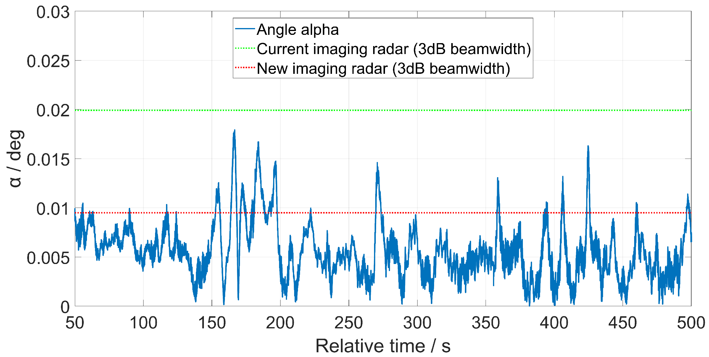
The new imaging radar, like its predecessor, requires guidance from the tracking radar. To ensure high-quality imaging, the object must be within the 3 dB beam width of the antenna for a sufficient observation interval. This requirement concerns the angle α between the antenna direction and the line of sight to the satellite, illustrated in Figure 23. Instead, the angle ϑ is the antenna 3 dB beam width, which, for the new imaging radar, is smaller than the current imaging radar due to the higher frequency band. The condition α ϑ / 2 must be satisfied to guarantee the object is within the antenna beam.
Figure 24 displays the beam’s pointing accuracy for a standard observation of TIRA. Two thresholds for angle α are depicted: the green one for the current imaging radar and the red one for the new imaging radar. Compared to the current imaging radar, the new system, due to its narrower beam width, requires improved tracking capabilities. Therefore, a new tracking filter has to be developed and implemented in the TIRA system.
As previously mentioned, TIRA measures the range, range rate, azimuth, and elevation of a space object in real time. A sensitivity analysis was performed to understand the impact of the accuracy of each radar observable on the tracking performance. Another investigation was conducted by including an additional parameter, the range-rate rate, as input to the tracking filter. This parameter can be estimated from the phase independently of the other observables [6]. An extended Kalman filter (EKF) was used for the simulations. Results showed that the tracking performance could be strongly improved by increasing the angular accuracy of the radar measurements. Instead, the other parameters (range, range rate, range-rate rate) only increased slightly the tracking performance [31].
A possibility to obtain angular measurements independent of the L-band radar is to take advantage of the imaging radar of the TIRA system directly during tracking. To achieve this, the imaging radar needs to be equipped with a monopulse system. The benefit of this is to provide more accurate angular data than those of the tracking radar, thanks to the higher frequency band. Therefore, it is possible to enhance the tracking performance by combining the information of the two radars of TIRA. A common technique is the multi-sensor data fusion that consists in combining the output of several sensors to describe a single probabilistic state [32].
A first investigation of the multi-sensor data fusion between the tracking and the imaging radar of the TIRA system was performed in [31]. Again, an EKF was used for the simulations. Results confirmed that the multi-sensor data fusion could be a solution to achieve a more accurate tracking system by ensuring the target object within the 3 dB beam width of the antenna of the future imaging radar.
Currently, different scenarios are being investigated based on the idea of a two-step tracking filter. It consists of two tracking filters running in parallel: an EKF and a batch least-squares filter. While the EKF tracks the object in real-time, the batch least-squares filter works in near real time by collecting data over a certain period of time. Every time the batch filter provides an output, it is injected in the EKF with the purpose of improving the tracking performance. Some first results are shown in [33]. Lastly, the implementation of an antenna steering function is needed to regulate the antenna pointing direction over time.

6.2. Challenges in High-Bandwidth Pulsed Radars

For ground-based imaging and tracking radars for space observation, the combination of stability, high transmit power, and bandwidth is essential to achieve long-range detection, a high resolution, and accurate velocity measurements.
In radar, the range resolution is directly related to the signal bandwidth, and a higher bandwidth therefore improves the spatial resolution in radar imaging while a high-power transmitter provides the SNR necessary for both accurate tracking and imaging.
Since the relative bandwidth available from high-power microwave tube amplifiers is in the order of 5 to 15%, it is clear that an enhancement of the range resolution requires a shift of the TIRA system imaging radar to a higher frequency band.

6.3. Real-Time Processing

Due to the narrow antenna lobe in the Ka band, the imaging radar is planned to also have a tracking capability to ensure optimum target illumination. Therefore, real-time processing of the acquired signals is required. Since arbitrary waveforms should be used, pulse compression using the deramping technique is not feasible. In order for any pulse compression filter to be applied, the received signal must be sampled in its entire bandwidth. Maximizing the pulse energy by increasing the pulse length to the maximum limit of the amplifier gives us a large number of samples per pulse which have to be Fourier transformed using a fast Fourier transform (FFT) for fast filtering. The calculation of one thousand FFTs per second with a size of about one million points is not reasonable to implement in a field-programmable gate array (FPGA). On the other hand, GPUs are very flexible and capable of handling these calculations on large datasets. The selected GPU-based solution enables a flexible data processing chain that implements pulse compression and tracking filters and even real-time ISAR imaging algorithms.

6.4. Ka-Band Transmitter

The transmission of microwave power, particularly in the higher frequency bands, is constrained by the availability of sufficiently powerful microwave amplifiers. To achieve a greater transmitted power than that permitted by commercially available high-power amplifiers, the output power of two electron vacuum tubes will be combined.
In addition to the RF high-power amplifier, an appropriate antenna front end is required that can handle and transmit the high power and bandwidth to the antenna. At the same time, it implements a duplexer that separates the sensitive receiver channel from the high-power transmission channel. Several radar systems have demonstrated that quasi-optical antenna front ends can handle the highest RF power and minimize the microwave losses compared to traditional waveguide-based systems [34,35,36].
In essence, a quasi-optical front end is a quasi-optical transmission line combined with a quasi-optical duplexer. The quasi-optical transmission line is a configuration of focusing mirrors that periodically refocus a diverging Gaussian microwave beam [37]. The quasi-optical duplexer uses the polarization of the Gaussian beam to separate the TX and RX signals. Key component of the duplexer is a quasi-optical Faraday rotator, which is a nonreciprocal polarization rotation device that can be used together with polarizing grids to construct the duplexer [38,39].
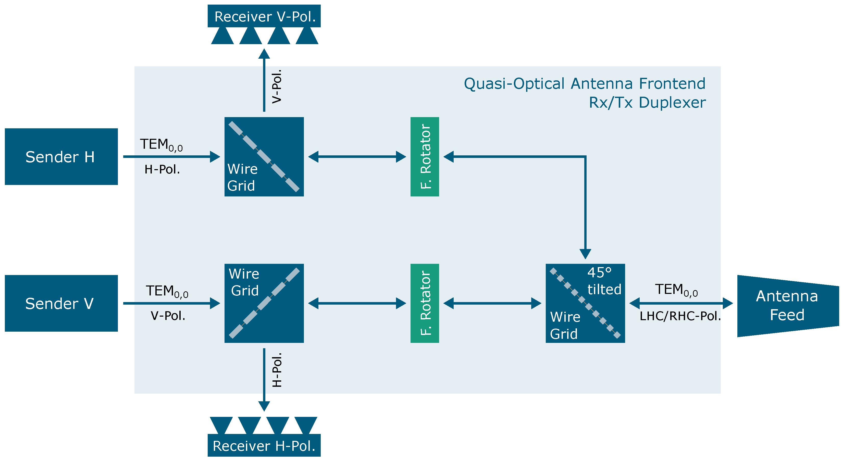
For the TIRA system upgrade, a quasi-optical antenna front end suitable for fully polarimetric radar operation (see Section 3.2) with a broad bandwidth and high transmission power will be implemented. A block diagram of the antenna front-end concept is shown in Figure 25.
The radar signal is individually amplified by the two high-power vacuum tube amplifiers and launched by two horn antennas as fundamental Gaussian beams ( TEM 0 , 0 mode) into the quasi-optical antenna front end which guides the RF to the antenna. In the transmission channel, the linearly polarized Gaussian beams are transmitted through wire grids following the horn antennas. The subsequent Faraday rotators are designed to rotate the polarization plane by 45°. In combination with the polarization-splitting wire grids, the Faraday rotators function as an efficient quasi-optical duplexer (see [34,36,39] for details). At the third wire grid, the power signals from both high-power amplifiers are combined.
The existing antenna geometry prevents direct quasi-optical coupling into the antenna as implemented, e.g., in [34]. Therefore, the power-combined signal is coupled by two adjustable mirrors into an oversized corrugated circular waveguide, which is used as the antenna feed due to limited space. However, oversized corrugated circular waveguides permit low-loss signal transmission similar to a quasi-optical beam line and support comparable high power levels [40].
The presented quasi-optical duplexer approach, which utilizes Faraday rotators and polarization-splitting wire grids, enables the simultaneous transmission and reception of RF signals with arbitrary polarization. The polarization of the transmitted signal is determined by the relative phase between the two high-power signals when they are combined at the third wire grid. This feature allows for the polarization of the transmit signal to be freely selected and switched from pulse to pulse or even within a pulse. The ability to freely select polarization with inter-pulse switching is a unique feature of the new TIRA system that will enable fully polarimetric measurements in the future (see Section 3.2).
As previously mentioned (see Section 6.3), target tracking for antenna guidance is required simultaneously to the imaging for the new Ka-band system. Therefore, in addition to its imaging and polarimetric radar capabilities, the quasi-optical antenna front end is designed to support simultaneous multimode monopulse tracking [34,41]. For this, the quasi-optical components are designed to support the propagation of the relevant higher-order Gaussian modes in the antenna front end, and a special multimode RX antenna similar to [42] is under development.
A further advantage of the quasi-optical duplexer are the low reflections in the transmit path and therefore a high isolation between the transmit and receive channels of > 40 dB. This reduces the demands on the power-limiters installed upstream of the receiver electronics, which are only required to absorb a small amount of power during transmission. Consequently, limiters with low transmission losses can be used, resulting in an increased SNR.

7. Conclusions

The space observation radar TIRA is undergoing a transformative upgrade in order to fulfill upcoming requirements for space domain awareness, space safety, and space sustainability. For this, the current imaging radar working in the Ku band will be replaced by a new imaging radar which will operate in the Ka band. With this new frequency band, a higher bandwidth will enable a higher spatial resolution for the radar images. The new Ka-band amplifiers will also provide significantly increased transmit power compared to the current Ku-band system. Together with the higher center frequency, a gain in sensitivity will be reached. Please note that some radar parameters are classified and cannot be listed in this paper. Another benefit of the new imaging radar will be the availability of fully polarimetric radar images. This will allow a much more detailed analysis of space objects. In addition, the complete processing control infrastructure of the current tracking radar in the L band is facing a major overhaul, which will enable continuous incremental upgrades in the future through a modular and open design. Tracking will be carried out in a new combined mode fusing the data acquired by the tracking and the imaging radars. Also, new signal processing techniques are under development to improve the characterization of space objects by improving the imaging quality and exploiting the polarimetric information.

Author Contributions

Writing—original draft, review and editing, J.K., F.B., C.C., D.C.-M., L.F., C.H., V.K., M.L., A.M., R.P., S.R. and F.R. All authors have read and agreed to the published version of the manuscript.

Funding

The projects detailed in this article are funded by the German Federal Ministry of Defence (BMVg).

Data Availability Statement

The original contributions presented in the study are included in the article, further inquiries can be directed to the corresponding author.

Conflicts of Interest

The authors declare no conflicts of interest.

Abbreviations

The following abbreviations are used in this manuscript:
ADCAnalog-to-digital conversion
ARCADIAARChitecture Analysis and Design Integrated Approach
ASATAnti-satellite
COTSCommercial off-the-shelf
DACDigital-to-analog conversion
DDCDigital down-conversion
DOADirection of arrival
DUCDigital up-conversion
ERPsEarth rotation parameters
ESAEuropean Space Agency
FFTFast Fourier transform
FHRFraunhofer Institute for High Frequency Physics and Radar Techniques
FMIFunctional Mock-up Interface
FPGAField-programmable gate array
GEOGeosynchronous equatorial orbit
GNSSGlobal navigation satellite system
GPUGraphical processing unit
ICRFInternational Celestial Reference Frame
ICRSInternational Celestial Reference System
IODInitial orbit determination
ISARInverse synthetic aperture radar
ITRFInternational Terrestrial Reference Frame
LEOLow Earth orbit
MBSEModel-based system engineering
MEOMedium Earth orbit
ONERAOffice national d’études et de recherches aérospatiales
PPPPrecise point positioning
PRFPulse repetition frequency
RCSRadar cross section
RFRadio frequency
RSOResident space object
RTKReal-time kinematics
SAPOSSatellite positioning service of the German surveying authorities
SNRSignal-to-noise ratio
SRPSolar radiation pressure
SSASpace situational awareness
TIRATracking and Imaging Radar
TLETwo-line-element
UTCCoordinated universal time

References

  1. Mehrholz, D. Radar techniques for the characterization of meter—Sized objects in space. Adv. Space Res. 2001, 28, 1259–1268. [Google Scholar] [CrossRef]
  2. Mehrholz, D.; Leushacke, F.W.; Jehn, R.; Klinkrad, H.; Landgraf, M. Detecting, tracking and imaging space debris. ESA Bull. 2002, 109, 128–134. [Google Scholar]
  3. Muntoni, G.; Montisci, G.; Pisanu, T.; Andronico, P.; Valente, G. Crowded Space: A Review on Radar Measurements for Space Debris Monitoring and Tracking. Appl. Sci. 2021, 11, 1364. [Google Scholar] [CrossRef]
  4. Sommer, S.; Rosebrock, J.; Cerutti-Maori, D.; Leushacke, L. Temporal analysis of ENVISAT’s rotational motion. In Proceedings of the 7th European Conference on Space Debris 2017, Darmstadt, Germany, 18–21 April 2017; Volume 7. [Google Scholar]
  5. Sommer, S.; Karamanavis, V.; Schlichthaber, F.; Patzelt, T.; Rosebrock, J.; Cerutti-Maori, D.; Leushacke, L. Analysis of the attitude motion and cross sectional area of TIANGONG-1 during its uncontrolled re-entry. In Proceedings of the 1st NEO and Debris Detection Conference, Darmstadt, Germany, 22–24 January 2019; Volume 1, p. 469. [Google Scholar]
  6. Cerutti-Maori, D.; Rosebrock, J.; Carloni, C.; Budoni, M.; Maouloud, I.; Klare, J. A novel High-Precision Observation Mode for the Tracking and Imaging Radar TIRA–Principle and Performance Evaluation. In Proceedings of the 8th European Conference on Space Debris, ESA/ESOC, Darmstadt, Germany, 20–23 April 2021. [Google Scholar]
  7. Karamanavis, V.; Dirks, H.; Fuhrmann, L.; Schlichthaber, F.; Egli, N.; Patzelt, T.; Klare, J. Characterization of deorbiting satellites and space debris with radar. Adv. Space Res. 2023, 72, 3269–3281. [Google Scholar] [CrossRef]
  8. Carloni, C.; Cerutti-Maori, D.; Budoni, M.; Rosebrock, J. Performance analysis of tracking filters according to input data processing. In Proceedings of the 8th European Conference on Space Debris, Darmstadt, Germany, 20–23 April 2021; Volume 8. [Google Scholar]
  9. Leushacke, L.; Czeslik, C. High doppler resolution monopulse techniques for the radar observation of targets in the geosynchronous ring. In Proceedings of the Proc. DGON/ITG International Radar Symposium, Munich, Germany, 15–17 September 1998; Volume 1, pp. 457–464. [Google Scholar]
  10. The End-of-Life Services by Astroscale Demonstrator (ELSA-d). Available online: https://astroscale.com/missions/elsa-d/ (accessed on 29 October 2024).
  11. Cerutti-Maori, D.; Carloni, C.; Rosebrock, J.; Maouloud, I. Improving the Performance of the Space Observation Radar TIRA through Dedicated Signal Processing Techniques and Advanced Experimental Modes. In Proceedings of the Sensors and Electronics Technology Panel and Systems Concepts and Integration Panel Specialists Meeting SET-SCI-297: “Space Sensors and Space Situational Awareness”, Interlaken, Switzerland, 10–11 October 2022. [Google Scholar]
  12. Chen, V.C.; Martorella, M. Inverse Synthetic Aperture Radar Imaging: Principles, Algorithms and Applications; Radar, Sonar and Navigation, Institution of Engineering and Technology; Wiley: Hoboken, NJ, USA, 2014. [Google Scholar]
  13. Final Images Before Aeolus Demise. Available online: https://www.esa.int/Space_Safety/Space_Debris/Final_images_before_Aeolus_demise (accessed on 29 October 2024).
  14. Kak, A.C.; Slaney, M. Principles of Computerized Tomographic Imaging; Society for Industrial and Applied Mathematics: Philadelphia, PA, USA, 2001. [Google Scholar] [CrossRef]
  15. Cerutti-Maori, D.; Carloni, C.; Rosebrock, J.; Siminski, J. Observation of COSMOS-1408 Debris Cloud with the Tracking and Imaging Radar (TIRA) System. In Proceedings of the 2nd NEO and Debris Detection Conference, Darmstadt, Germany, 24–26 January 2023. [Google Scholar]
  16. Available online: https://web.archive.org/web/20220225183304/https://www.yuzhnoye.com/en/company/history/electronic-surveillance-spacecraft.html (accessed on 17 January 2024).
  17. Serrano, A.; Kobsa, A.; Uysal, F.; Cerutti-Maori, D.; Ghio, S.; Kintz, A.; Morrison, R.L., Jr.; Welch, S.; van Dorp, P.; Hogan, G.; et al. Long baseline bistatic radar imaging of tumbling space objects for enhancing space domain awareness. IET Radar Sonar Navig. 2024, 18, 598–619. [Google Scholar] [CrossRef]
  18. Available online: https://commons.wikimedia.org/wiki/File:Landsat-9_Centaur_1_(cropped).jpg (accessed on 29 October 2024).
  19. Available online: https://www.esa.int/Space_Safety/Space_Debris/Space_debris_by_the_numbers (accessed on 15 August 2024).
  20. Available online: https://ourworldindata.org/grapher/yearly-number-of-objects-launched-into-outer-space (accessed on 21 August 2024).
  21. Van Zyl, J.; Kim, Y. Mathematical representations of scatterers. In Synthetic Aperture Radar Polarimetry; Yuen, J.H., Ed.; Wiley: Hoboken, NY, USA, 2011; p. 29. [Google Scholar]
  22. Voirin, J.L. (Ed.) Model-Based System and Architecture Engineering with the Arcadia Method; Implementation of model based system engineering set; ISTE Press: London, UK, 2018. [Google Scholar]
  23. Creager, R.; Whitehead, M. Refactoring GBT software to support high data rate instruments using data streaming technology. Softw. Cyberinfrastructure Astron. III 2014, 9152, 91520X. [Google Scholar] [CrossRef]
  24. Lyard, E.; Walter, R.; Kosack, K.; Jacquemier, J.; Oya, I.; Wegner, P.; Fuessling, M.; Wu, X.; Consortium, F. Modern middleware for the data acquisition of the Cherenkov Telescope Array. arXiv 2015, arXiv:1508.06473. [Google Scholar]
  25. Spata, M.; Ruf, B.; Mehrholz, D.; Steinheuer, B.; Buck, G. Die Bestimmung der Großradaranlage des FGAN-Forschungsinstituts in Werthhoven im Bezugssystem ETRS 89. Vermess. Und Raumordn. 1998, 60, 430–437. [Google Scholar]
  26. Ince, E.S.; Barthelmes, F.; Reißland, S.; Elger, K.; Förste, C.; Flechtner, F.; Schuh, H. ICGEM—15 years of successful collection and distribution of global gravitational models, associated services, and future plans. Earth Syst. Sci. Data 2019, 11, 647–674. [Google Scholar] [CrossRef]
  27. Petit, G.; Luzum, B. (Eds.) IERS Conventions (2010); Number 36 in IERS technical note; Verl. des Bundesamtes für Kartographie und Geodäsie: Frankfurt am Main, Germany, 2010. [Google Scholar]
  28. International Telecommunication Union. ITU-R P.676: Attenuation by Atmospheric Gases and Related Effects; International Telecommunication Union: Geneva, Switzerland, 2019. [Google Scholar]
  29. International Telecommunication Union. ITU-R P.840: Attenuation due to Clouds and Fog; International Telecommunication Union: Geneva, Switzerland, 2019. [Google Scholar]
  30. International Telecommunication Union. ITU-R P.838: Specific Attenuation Model for Rain for Use in Prediction Methods; International Telecommunication Union: Geneva, Switzerland, 2005. [Google Scholar]
  31. Carloni, C.; Cerutti-Maori, D.; Budoni, M.; Rosebrock, J.; Maouloud, I.; Stoll, E. Improving the tracking performance of space observation radar systems. Adv. Space Res. 2024, 73, 6066–6078. [Google Scholar] [CrossRef]
  32. DeMars, K.; McCabe, J.; Darling, J. Collaborative Multi-Sensor Tracking and Data Fusion. In Proceedings of the 5th AAS/AIAA Space Flight Mechanics Meeting, Williamsburg, VA, USA, 11–15 January 2015. [Google Scholar]
  33. Carloni, C.; Cerutti-Maori, D.; Maouloud, I.O.; Stoll, E. A novel tracking approach based on data fusion for multi-frequency space observation radar systems. Acta Astronaut. 2024; to be submitted. [Google Scholar]
  34. Fitzgerald, W.D. A 35-GHz beam waveguide system for the millimeter-wave radar. Linc. Lab. J. 1992, 5, 245–272. [Google Scholar]
  35. Stambaugh, J.J.; Lee, R.K.; Cantrell, W.H. The 4 GHz bandwidth millimeter-wave radar. Linc. Lab. J. 2012, 19, 64–76. [Google Scholar]
  36. Jamnejad, V.; Long, E.; Durden, S. Design of a quasi optical transmission line for Cloud and precipitation radar system of ACE mission. In Proceedings of the 2015 IEEE Aerospace Conference, Big Sky, MT, USA, 7–14 March 2015; pp. 1–6. [Google Scholar] [CrossRef]
  37. Goldsmith, P.F. Gaussian Beams and Antenna Feed Systems. In Quasioptical Systems: Gaussian Beam Quasioptical Propagation and Applications; Wiley-IEEE Press: Hoboken, NJ, USA, 1998; pp. 125–156. [Google Scholar] [CrossRef]
  38. Webb, M.R. A mm-wave four-port quasi-optical circulator. Int. J. Infrared Millim. Waves 1991, 12, 45–63. [Google Scholar] [CrossRef]
  39. Hunter, R.I.; Robertson, D.A.; Goy, P.; Smith, G.M. Design of High-Performance Millimeter Wave and Sub-Millimeter Wave Quasi-Optical Isolators and Circulators. IEEE Trans. Microw. Theory Tech. 2007, 55, 890–898. [Google Scholar] [CrossRef]
  40. Clarricoats, P.; Saha, P. Attenuation in corrugated circular wave-guide. Electron. Lett. 1970, 6, 370–372. [Google Scholar] [CrossRef]
  41. Clarricoats, P.J.B.; Elliot, R.D. Multimode corrugated waveguide feed for monopulse radar. IEE Proc. Microwaves Opt. Antennas 1981, 128, 102. [Google Scholar] [CrossRef]
  42. Dubrovka, F.F.; Piltyay, S.; Ovsyanik, Y.A.; Dubrovka, R. Eight-channel directional coupler of orthogonal H21 modes in circular waveguide for X-band quasi-monopulse antenna systems. Radioelectron. Commun. Syst. 2020, 63, 656–665. [Google Scholar] [CrossRef]
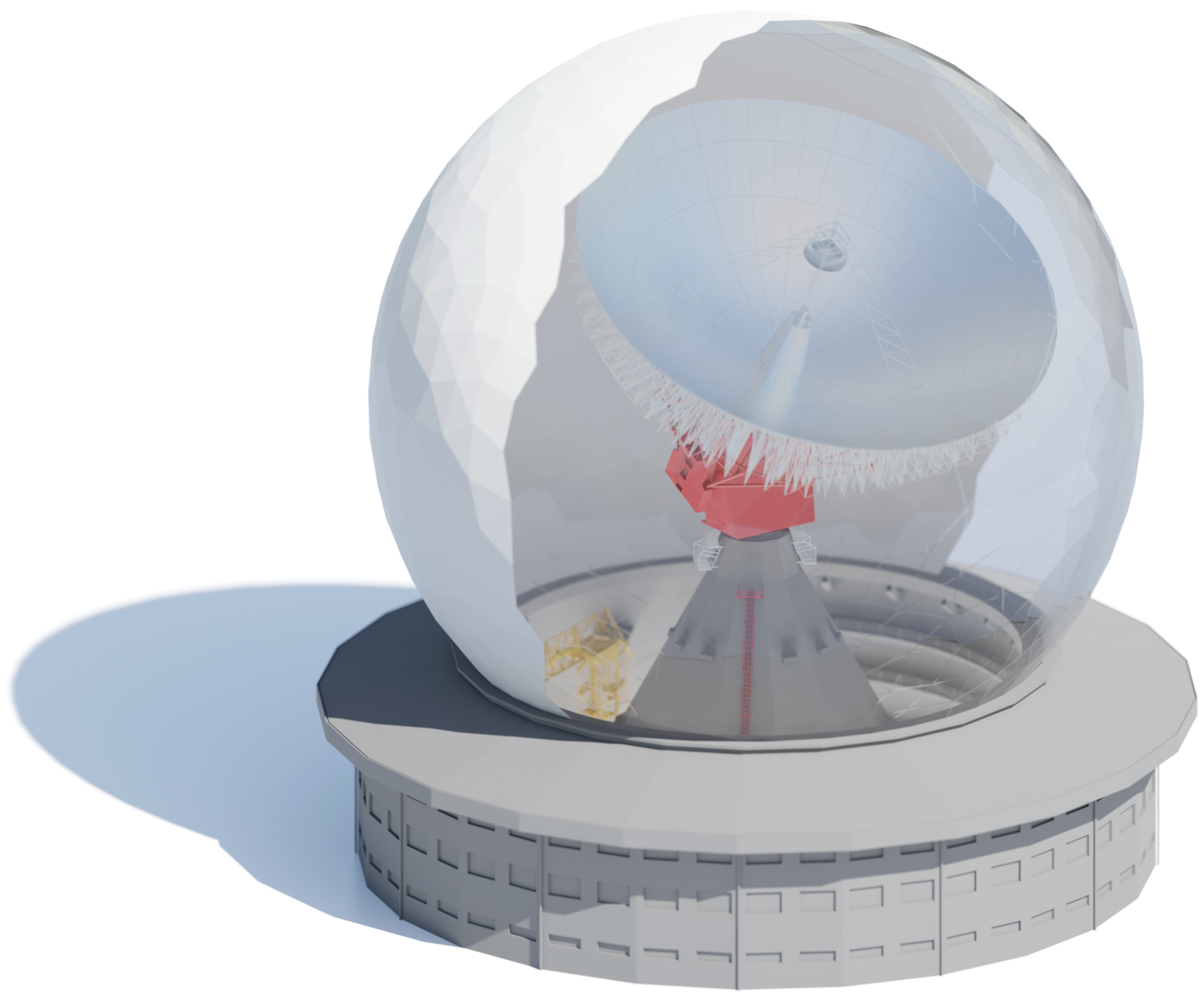
Figure 1. Illustration of the Tracking and Imaging Radar, TIRA. The system’s 34 m fully movable parabolic antenna and radar systems are protected by a 47.5 m radome. The surrounding 3-story building houses offices and laboratories associated with FHR’s research activities in SSA as well as technical infrastructure necessary for the operation of the TIRA system.
Remotesensing 16 04197 g001
Figure 2. Block diagram illustrating the current system architecture of TIRA. Components of the tracking radar are shown in dark blue, the imaging radar is show in turquoise, and common system components have a light blue background.
Remotesensing 16 04197 g002
Figure 3. Sentinel−3B (27 January 2021) [6].
Remotesensing 16 04197 g003
Figure 4. ELSA-D and ELSA-D CLIENT [10].
Remotesensing 16 04197 g004
Figure 5. Astroscale exercise (8 April 2022) [11].
Remotesensing 16 04197 g005
Figure 6. NILESAT cluster (16 March 2023).
Remotesensing 16 04197 g006
Figure 7. (ah) Series of ISAR images of AEOLUS obtained during its last pass observed by TIRA on 28 July 2023 [13].
Remotesensing 16 04197 g007
Figure 8. Jason-2 (13 October 2022).
Remotesensing 16 04197 g008
Figure 9. Cosmos-1408 (1 December 2021) computed with an angular velocity of 92.3 deg/s.
Remotesensing 16 04197 g009
Figure 10. Tselina-D model [16].
Remotesensing 16 04197 g010
Figure 11. Atlas-5 Centaur rocket body (16 March 2023) [17].
Remotesensing 16 04197 g011
Figure 12. Photo of an Atlas-5 Centaur rocket body [18].
Remotesensing 16 04197 g012
Figure 13. United Nations Office for Outer Space Affairs’ (2024), with major processing by Our World in Data, “Annual number of objects launched into space—NOOSA” [dataset]. United Nations Office for Outer Space Affairs’ “Online Index of Objects Launched into Outer Space” [original data] [20].
Remotesensing 16 04197 g013
Figure 14. Bistatic polarized ISAR images of a space object.
Remotesensing 16 04197 g014
Figure 15. Block diagram illustrating the future TIRA system architecture for enhanced space observation capabilities as a research instrument and an operational radar system.
Remotesensing 16 04197 g015
Figure 16. Overview of the ARCADIA method for MBSE.
Remotesensing 16 04197 g016
Figure 17. Illustration of the digital twin and model-based design concepts using TIRA’s high-precision position control as an example.
Remotesensing 16 04197 g017
Figure 18. Principle integration of system models into the operational software of TIRA utilizing the open FMI standard.
Remotesensing 16 04197 g018
Figure 19. Orientation of the system’s azimuth axis in a global reference frame via local measurements against the true vertical.
Remotesensing 16 04197 g019
Figure 20. History of the measured deviation of the antenna’s azimuth axis from the true vertical.
Remotesensing 16 04197 g020
Figure 21. Block diagram of the new system architecture for the TIRA tracking radar implementing the software-defined radio principle (Depicted satellite: Trisat, CC BY-SA 4.0 https://creativecommons.org/licenses/by-sa/4.0, accessed on 29 October 2024, via Wikimedia Commons).
Remotesensing 16 04197 g021
Figure 22. Modeled specific attenuation for precipitation, liquid water, and atmospheric gases with different relative humidity and temperature values along the ITU-assigned IEEE radar bands.
Remotesensing 16 04197 g022
Figure 23. Geometry of the angles ϑ and α . ϑ is the 3 dB beam width of the antenna. α is the angle between the antenna pointing direction and the line of sight to the satellite with the origin at the radar.
Remotesensing 16 04197 g023
Figure 24. Beam’s pointing accuracy of the TIRA system during a standard tracking observation.
Remotesensing 16 04197 g024
Figure 25. Principle block diagram of the high-power polarimetric quasi-optical monopulse front end.
Remotesensing 16 04197 g025
Disclaimer/Publisher’s Note: The statements, opinions and data contained in all publications are solely those of the individual author(s) and contributor(s) and not of MDPI and/or the editor(s). MDPI and/or the editor(s) disclaim responsibility for any injury to people or property resulting from any ideas, methods, instructions or products referred to in the content.