
A Parameter Estimation-Based Anti-Deception Jamming Method for RIS-Aided Single-Station Radar


Abstract
:1. Introduction
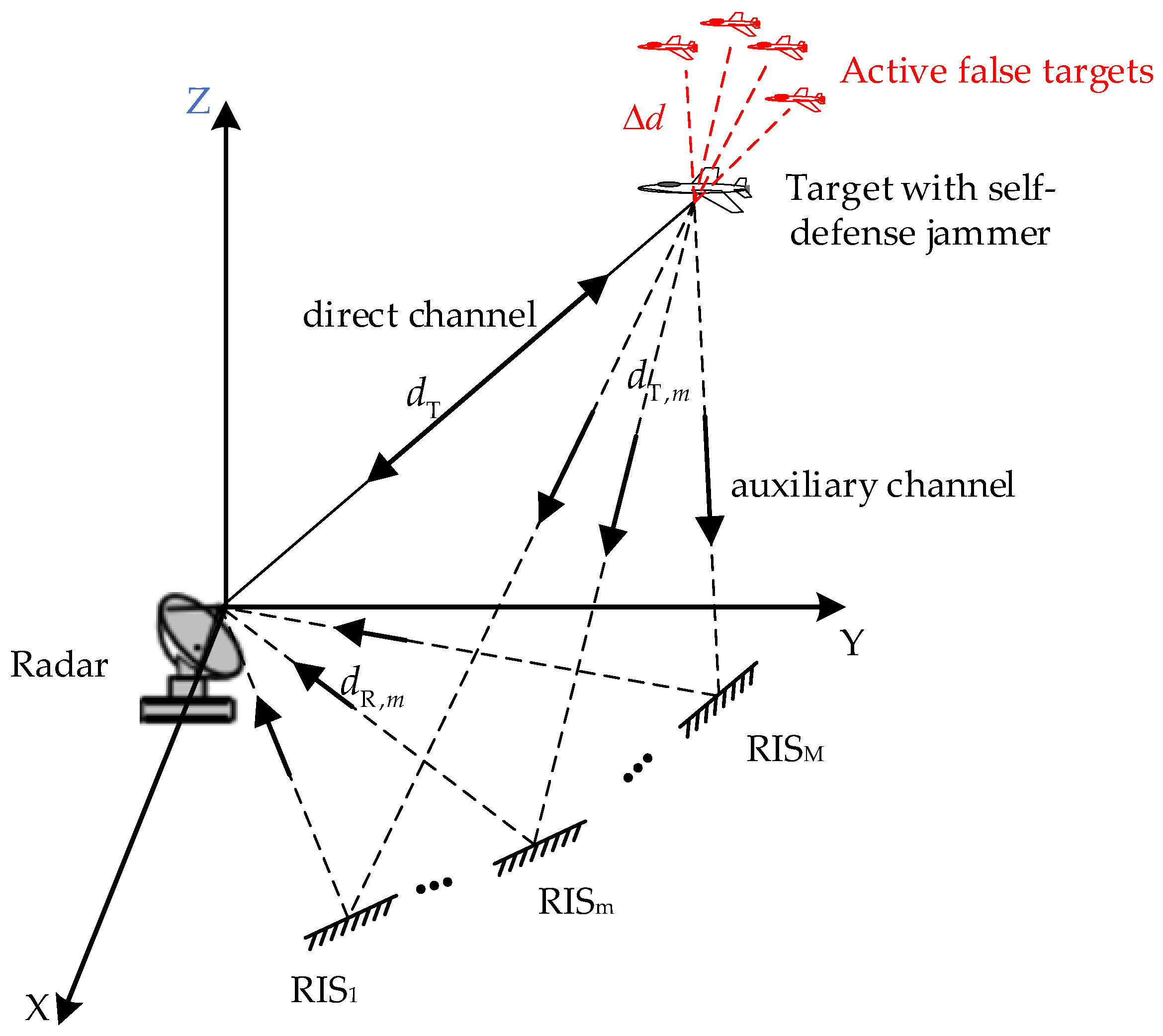
2. System Model
3. Deception Parameter Estimates
3.1. Deception Parameter Estimation Method
3.2. CRLB
4. Active False Target Discrimination
5. Numerical Experiments
5.1. Simulation Analysis of Active False Target Discrimination Probability
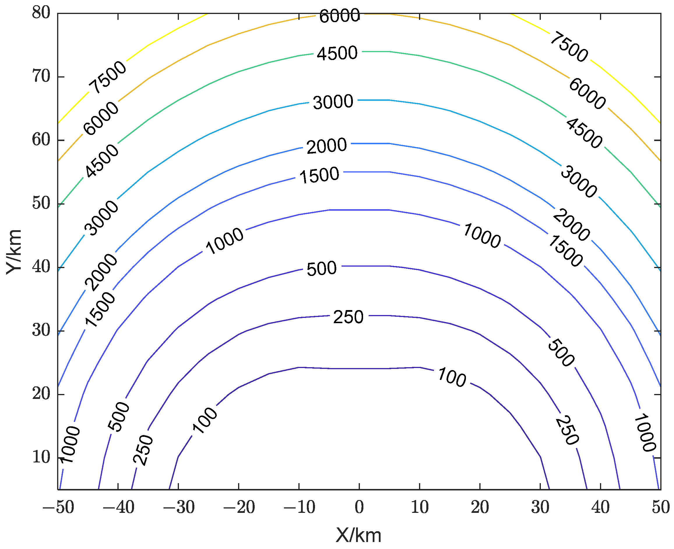
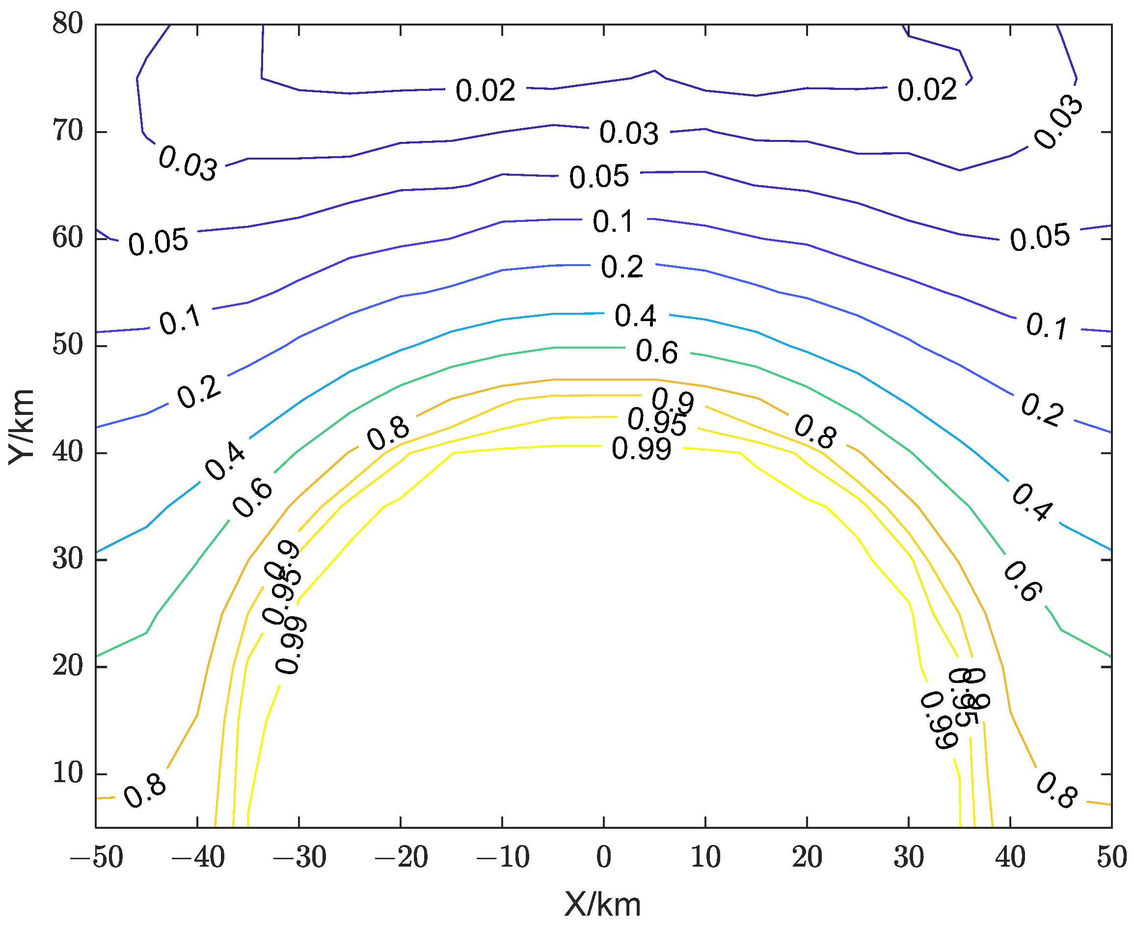
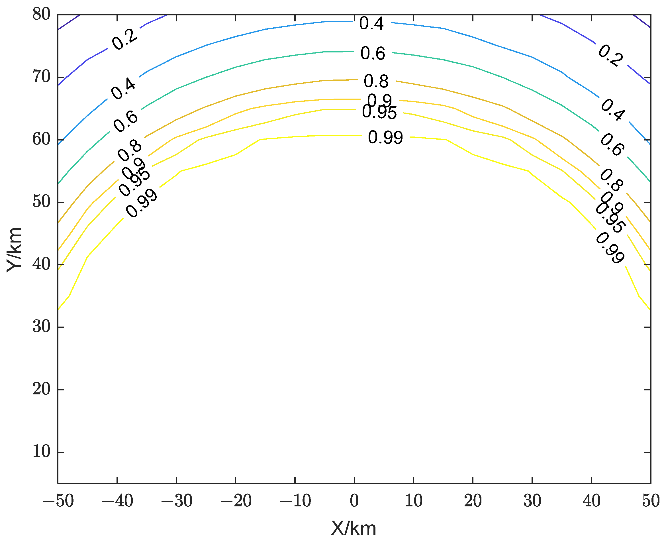
5.2. Analysis of the Influence of Jammer Location
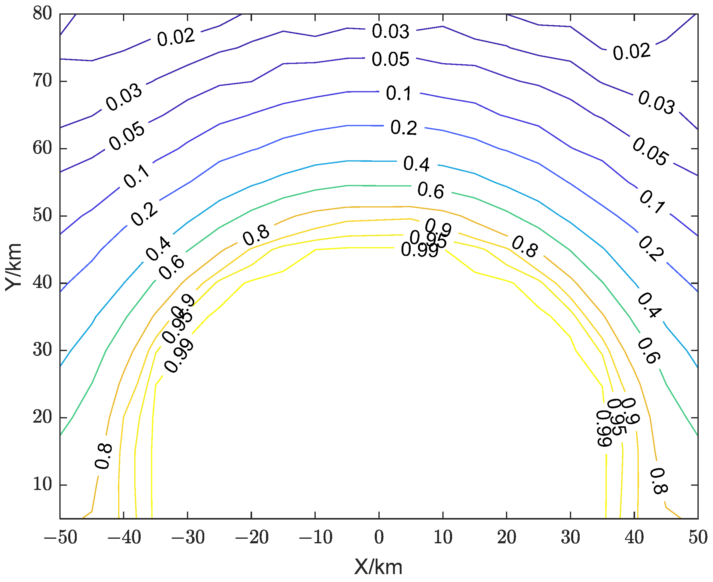
5.3. Analysis of the Impact of Multi-RIS Site Deployment
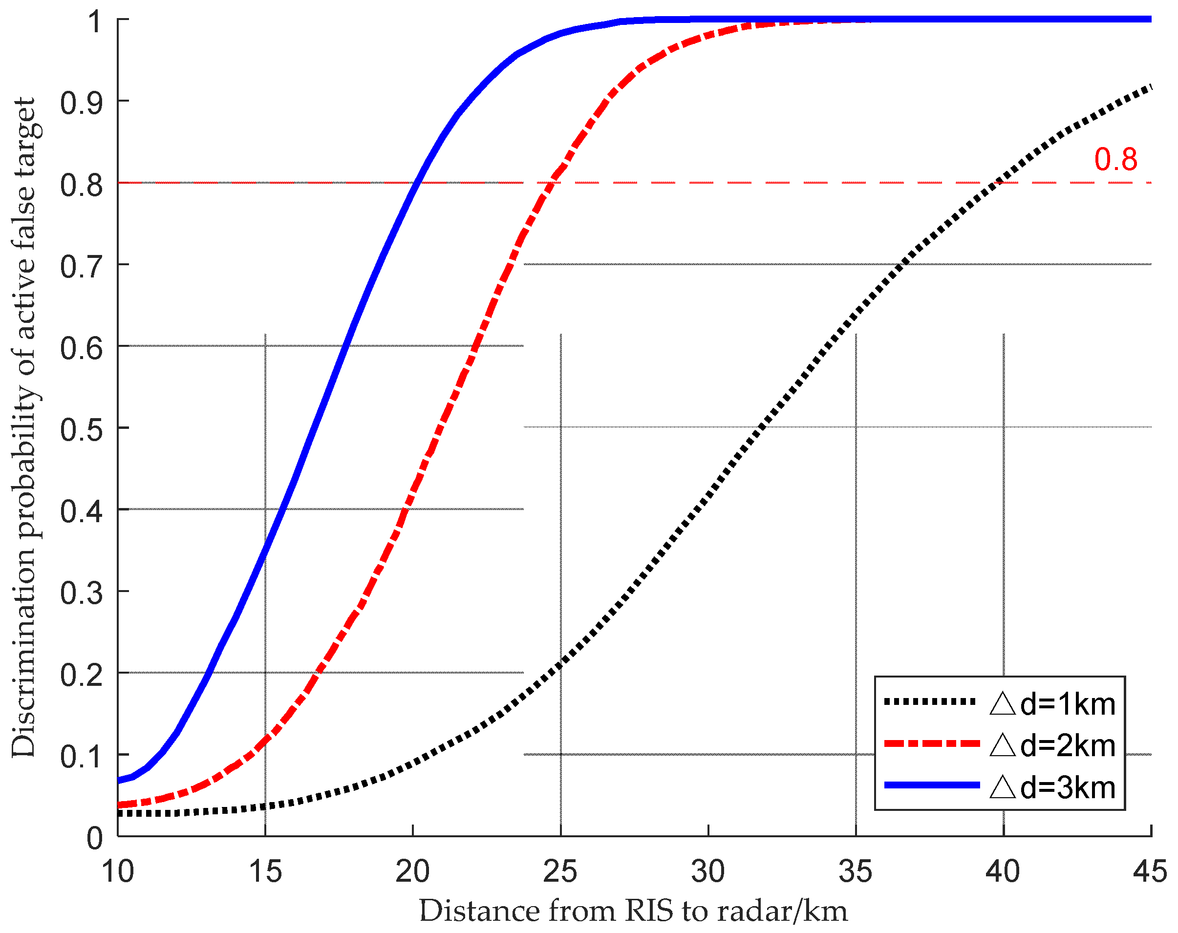
5.4. Analysis of the Impact of Distance Between RIS and Radar
6. Conclusions
Author Contributions
Funding
Data Availability Statement
Conflicts of Interest
References
- Solomitckii, D.; Barneto, C.B.; Turunen, M.; Allén, M.; Zhabko, G.P.; Zavjalov, S.V.; Volvenko, S.V.; Valkama, M. Millimeter-Wave Radar Scheme with Passive Reflector for Uncontrolled Blind Urban Intersection. IEEE Trans. Veh. Technol. 2021, 70, 7335–7346. [Google Scholar] [CrossRef]
- Costes, C.; Artis, J.-P.; Kemkemian, S.; Garello, R.; Mercier, G. Weather Hazard Interpretation and Forecast by an Airborne Radar. In Proceedings of the 2009 International Radar Conference “Surveillance for a Safer World” (RADAR 2009), Bordeaux, France, 12–16 October 2009; pp. 1–6. [Google Scholar]
- Dill, S.; Schreiber, E.; Engel, M.; Heinzel, A.; Peichl, M. A Drone Carried Multichannel Synthetic Aperture Radar for Advanced Buried Object Detection. In Proceedings of the 2019 IEEE Radar Conference (RadarConf), Boston, MA, USA, 22–26 April 2019; pp. 1–6. [Google Scholar]
- Li, Y.; Chen, J.; Zhu, J. A New Ground Accelerating Target Imaging Method for Airborne CSSAR. IEEE Geosci. Remote Sens. Lett. 2024, 21, 4013305. [Google Scholar] [CrossRef]
- Liu, F.; Huang, P.; Tan, W.; Ren, H. Portable Omni-Directional Micro Deformation Monitoring Radar System. In Proceedings of the 2020 IEEE MTT-S International Microwave Workshop Series on Advanced Materials and Processes for RF and THz Applications (IMWS-AMP), Suzhou, China, 29–31 July 2020; pp. 1–3. [Google Scholar]
- Ling, Z.; Zhaofa, Z.; Jing, L.; Jingyi, L.; Zhipeng, H.; Jianmin, Z. Lunar Penetrating Radar Data Processing and Analysis Based on CEEMD. In Proceedings of the 2018 17th International Conference on Ground Penetrating Radar (GPR), Rapperswil, Switzerland, 18–21 June 2018; pp. 1–4. [Google Scholar]
- Spezio, A.E. Electronic Warfare Systems. IEEE Trans. Microw. Theory Tech. 2002, 50, 633–644. [Google Scholar] [CrossRef]
- Schroer, R. Electronic Warfare. [A Century of Powered Flight: 1903–2003]. IEEE Aerosp. Electron. Syst. Mag. 2003, 18, 49–54. [Google Scholar] [CrossRef]
- Zhang, S.; Zhou, Y.; Zhang, L.; Zhang, Q.; Du, L. Target Detection for Multistatic Radar in the Presence of Deception Jamming. IEEE Sens. J. 2021, 21, 8130–8141. [Google Scholar] [CrossRef]
- Javadi, S.H.; Farina, A. Radar Networks: A Review of Features and Challenges. Inf. Fusion 2020, 61, 48–55. [Google Scholar] [CrossRef]
- Griffiths, H. Developments in Bistatic and Networked Radar. In Proceedings of the 2011 IEEE CIE International Conference on Radar, Chengdu, China, 24–27 October 2011; pp. 10–13. [Google Scholar]
- Chernyak, V.S. Fundamentals of Multisite Radar Systems: Multistatic Radars and Multistatic Radar Systems; Routledge: London, UK, 1998; ISBN 978-0-203-75522-8. [Google Scholar]
- Deng, H. Orthogonal Netted Radar Systems. IEEE Aerosp. Electron. Syst. Mag. 2012, 27, 28–35. [Google Scholar] [CrossRef]
- Gaoqian, Z.; Ying, Z. Radar Netting Technology & Its Development. In Proceedings of the 2011 IEEE CIE International Conference on Radar, Chengdu, China, 24–27 October 2011; Volume 1, pp. 933–937. [Google Scholar]
- Greco, M.S.; Stinco, P.; Gini, F.; Farina, A. Cramer-Rao Bounds and Selection of Bistatic Channels for Multistatic Radar Systems. IEEE Trans. Aerosp. Electron. Syst. 2011, 47, 2934–2948. [Google Scholar] [CrossRef]
- Blunt, S.D.; Gerlach, K. Multistatic Adaptive Pulse Compression. IEEE Trans. Aerosp. Electron. Syst. 2006, 42, 891–903. [Google Scholar] [CrossRef]
- Robey, F.C.; Coutts, S.; Weikle, D.; McHarg, J.C.; Cuomo, K. MIMO Radar Theory and Experimental Results. In Proceedings of the Conference Record of the Thirty-Eighth Asilomar Conference on Signals, Systems and Computers, Pacific Grove, CA, USA, 7–10 November 2004; Volume 1, pp. 300–304. [Google Scholar]
- Donnet, B.J.; Longstaff, I.D. MIMO Radar, Techniques and Opportunities. In Proceedings of the 2006 European Radar Conference, Manchester, UK, 13–15 September 2006; pp. 112–115. [Google Scholar]
- Fishler, E.; Haimovich, A.; Blum, R.S.; Cimini, L.J.; Chizhik, D.; Valenzuela, R.A. Spatial Diversity in Radars—Models and Detection Performance. IEEE Trans. Signal Process. 2006, 54, 823–838. [Google Scholar] [CrossRef]
- Sun, T.; Wang, W. Efficient Multistatic Radar Localization Algorithms for a Uniformly Accelerated Moving Object With Sensor Parameter Errors. IEEE Trans. Aerosp. Electron. Syst. 2023, 59, 7559–7574. [Google Scholar] [CrossRef]
- Zhao, S.; Liu, N.; Zhang, L.; Zhou, Y.; Li, Q. Discrimination of Deception Targets in Multistatic Radar Based on Clustering Analysis. IEEE Sens. J. 2016, 16, 2500–2508. [Google Scholar] [CrossRef]
- Fang, Y.; Zhu, S.; Liao, B.; Li, X.; Liao, G. Target Localization with Bistatic MIMO and FDA-MIMO Dual-Mode Radar. IEEE Trans. Aerosp. Electron. Syst. 2024, 60, 6925–6940. [Google Scholar] [CrossRef]
- Cui, T.J.; Qi, M.Q.; Wan, X.; Zhao, J.; Cheng, Q. Coding Metamaterials, Digital Metamaterials and Programmable Metamaterials. Light Sci. Appl. 2014, 3, e218. [Google Scholar] [CrossRef]
- Björnson, E.; Wymeersch, H.; Matthiesen, B.; Popovski, P.; Sanguinetti, L.; de Carvalho, E. Reconfigurable Intelligent Surfaces: A Signal Processing Perspective With Wireless Applications. IEEE Signal Process. Mag. 2022, 39, 135–158. [Google Scholar] [CrossRef]
- ElMossallamy, M.A.; Zhang, H.; Song, L.; Seddik, K.G.; Han, Z.; Li, G.Y. Reconfigurable Intelligent Surfaces for Wireless Communications: Principles, Challenges, and Opportunities. IEEE Trans. Cogn. Commun. Netw. 2020, 6, 990–1002. [Google Scholar] [CrossRef]
- Binucci, F.; Banelli, P.; Di Lorenzo, P.; Barbarossa, S. Adaptive Resource Optimization for Edge Inference with Goal-Oriented Communications. EURASIP J. Adv. Signal Process. 2022, 2022, 123. [Google Scholar] [CrossRef]
- Guo, M.; Lin, Z.; Ma, R.; An, K.; Li, D.; Al-Dhahir, N.; Wang, J. Inspiring Physical Layer Security With RIS: Principles, Applications, and Challenges. IEEE Open J. Commun. Soc. 2024, 5, 2903–2925. [Google Scholar] [CrossRef]
- Wu, Q.; Zhang, S.; Zheng, B.; You, C.; Zhang, R. Intelligent Reflecting Surface-Aided Wireless Communications: A Tutorial. IEEE Trans. Commun. 2021, 69, 3313–3351. [Google Scholar] [CrossRef]
- Naeem, F.; Ali, M.; Kaddoum, G.; Huang, C.; Yuen, C. Security and Privacy for Reconfigurable Intelligent Surface in 6G: A Review of Prospective Applications and Challenges. IEEE Open J. Commun. Soc. 2023, 4, 1196–1217. [Google Scholar] [CrossRef]
- You, C.; Zheng, B.; Zhang, R. Wireless Communication via Double IRS: Channel Estimation and Passive Beamforming Designs. IEEE Wirel. Commun. Lett. 2021, 10, 431–435. [Google Scholar] [CrossRef]
- Sun, G.; He, R.; Ai, B.; Ma, Z.; Li, P.; Niu, Y.; Ding, J.; Fei, D.; Zhong, Z. A 3D Wideband Channel Model for RIS-Assisted MIMO Communications. IEEE Trans. Veh. Technol. 2022, 71, 8016–8029. [Google Scholar] [CrossRef]
- Souto, N. Joint Active and Passive Beamforming for RIS-Aided MIMO Communications With Low-Resolution Phase Shifts. IEEE Commun. Lett. 2023, 27, 1604–1608. [Google Scholar] [CrossRef]
- Li, G.-H.; Yue, D.-W.; Jin, S.-N. Spatially Correlated Rayleigh Fading Characteristics of RIS-Aided mmWave MIMO Communications. IEEE Commun. Lett. 2023, 27, 2222–2226. [Google Scholar] [CrossRef]
- Wang, D.; Zhao, Y.; He, Y.; Tang, X.; Li, L.; Zhang, R.; Zhai, D. Passive Beamforming and Trajectory Optimization for Reconfigurable Intelligent Surface-Assisted UAV Secure Communication. Remote Sens. 2021, 13, 4286. [Google Scholar] [CrossRef]
- Luo, S.; Yang, P.; Che, Y.; Yang, K.; Wu, K.; Teh, K.C.; Li, S. Spatial Modulation for RIS-Assisted Uplink Communication: Joint Power Allocation and Passive Beamforming Design. IEEE Trans. Commun. 2021, 69, 7017–7031. [Google Scholar] [CrossRef]
- Guo, Y.; Qin, Z.; Liu, Y.; Al-Dhahir, N. Intelligent Reflecting Surface Aided Multiple Access Over Fading Channels. IEEE Trans. Commun. 2021, 69, 2015–2027. [Google Scholar] [CrossRef]
- Li, J.; Xue, H.; Wu, M.; Wang, F.; Gao, T.; Zhou, F. Energy Efficiency Performance in RIS-Based Integrated Satellite–Aerial–Terrestrial Relay Networks with Deep Reinforcement Learning. EURASIP J. Adv. Signal Process. 2023, 2023, 121. [Google Scholar] [CrossRef]
- Asif Haider, M.; Zhang, Y.D.; Aboutanios, E. ISAC System Assisted by RIS with Sparse Active Elements. EURASIP J. Adv. Signal Process. 2023, 2023, 20. [Google Scholar] [CrossRef]
- Abeywickrama, S.; Zhang, R.; Wu, Q.; Yuen, C. Intelligent Reflecting Surface: Practical Phase Shift Model and Beamforming Optimization. IEEE Trans. Commun. 2020, 68, 5849–5863. [Google Scholar] [CrossRef]
- Chen, J. Multi-User Communications for Line-of-Sight Large Intelligent Surface Systems. EURASIP J. Adv. Signal Process. 2023, 2023, 129. [Google Scholar] [CrossRef]
- Chen, P.; Chen, Z.; Zheng, B.; Wang, X. Efficient DOA Estimation Method for Reconfigurable Intelligent Surfaces Aided UAV Swarm. IEEE Trans. Signal Process. 2022, 70, 743–755. [Google Scholar] [CrossRef]
- Wang, D.; Chen, P.; Wang, R. Cooperative Target Detection Based on UAV Jitter Model. In Proceedings of the 2022 IEEE 8th International Conference on Computer and Communications (ICCC), Chengdu, China, 9–12 December 2022; pp. 1835–1839. [Google Scholar]
- Jiang, Z.-M.; Deng, Q.; Huang, M.; Zheng, Z.; Wang, X.; Rihan, M. Intelligent Reflecting Surface Aided Co-Existing Radar and Communication System. Digit. Signal Process. 2023, 141, 104184. [Google Scholar] [CrossRef]
- Jiang, Z.-M.; Rihan, M.; Zhang, P.; Huang, L.; Deng, Q.; Zhang, J.; Mohamed, E.M. Intelligent Reflecting Surface Aided Dual-Function Radar and Communication System. IEEE Syst. J. 2022, 16, 475–486. [Google Scholar] [CrossRef]
- Fang, S.; Chen, G.; Xu, P.; Tang, J.; Chambers, J.A. SINR Maximization for RIS-Assisted Secure Dual-Function Radar Communication Systems. In Proceedings of the 2021 IEEE Global Communications Conference (GLOBECOM), Madrid, Spain, 7–11 December 2021; pp. 1–6. [Google Scholar]
- Wei, T.; Wu, L.; Mishra, K.V.; Shankar, M.R.B. Multiple IRS-Assisted Wideband Dual-Function Radar-Communication. In Proceedings of the 2022 2nd IEEE International Symposium on Joint Communications & Sensing (JC&S), Seefeld, Austria, 9 March 2022; pp. 1–5. [Google Scholar]
- Hu, S.; Rusek, F.; Edfors, O. Beyond Massive MIMO: The Potential of Positioning With Large Intelligent Surfaces. IEEE Trans. Signal Process. 2018, 66, 1761–1774. [Google Scholar] [CrossRef]
- Wymeersch, H.; He, J.; Denis, B.; Clemente, A.; Juntti, M. Radio Localization and Mapping With Reconfigurable Intelligent Surfaces: Challenges, Opportunities, and Research Directions. IEEE Veh. Technol. Mag. 2020, 15, 52–61. [Google Scholar] [CrossRef]
- Elzanaty, A.; Guerra, A.; Guidi, F.; Alouini, M.-S. Reconfigurable Intelligent Surfaces for Localization: Position and Orientation Error Bounds. IEEE Trans. Signal Process. 2021, 69, 5386–5402. [Google Scholar] [CrossRef]
- Buzzi, S.; Grossi, E.; Lops, M.; Venturino, L. Radar Target Detection Aided by Reconfigurable Intelligent Surfaces. IEEE Signal Process. Lett. 2021, 28, 1315–1319. [Google Scholar] [CrossRef]
- Lu, W.; Deng, B.; Fang, Q.; Wen, X.; Peng, S. Intelligent Reflecting Surface-Enhanced Target Detection in MIMO Radar. IEEE Sens. Lett. 2021, 5, 7000304. [Google Scholar] [CrossRef]
- Ye, J.; Peng, Y.; Zhang, P.; Li, Q.; Huang, L. RIS-Assisted Radar NLOS Target Detection. In Proceedings of the 2022 5th International Conference on Information Communication and Signal Processing (ICICSP), Shenzhen, China, 26 November 2022; pp. 630–635. [Google Scholar]
- Aubry, A.; De Maio, A.; Rosamilia, M. Reconfigurable Intelligent Surfaces for N-LOS Radar Surveillance. IEEE Trans. Veh. Technol. 2021, 70, 10735–10749. [Google Scholar] [CrossRef]
- Zou, H.; Wu, L.; Zhang, Z.; Gong, Z.; Dang, J.; Zhu, B. Position and Velocity Measurement in Dual RIS-Assisted Radar Systems. Sci. Sin. Inf. 2023, 53, 2527. [Google Scholar] [CrossRef]
- Fascista, A.; Coluccia, A.; Wymeersch, H.; Seco-Granados, G. RIS-Aided Joint Localization and Synchronization with a Single-Antenna Mmwave Receiver. In Proceedings of the ICASSP 2021—2021 IEEE International Conference on Acoustics, Speech and Signal Processing (ICASSP), Toronto, ON, Canada, 6 June 2021; pp. 4455–4459. [Google Scholar]
- Liu, Z.; Zhao, S.; Xie, B.; An, J. Reconfigurable Intelligent Surface Assisted Target Three-Dimensional Localization with 2-D Radar. Remote Sens. 2024, 16, 1936. [Google Scholar] [CrossRef]
- Wang, F.; Li, H.; Fang, J. Joint Active and Passive Beamforming for IRS-Assisted Radar. IEEE Signal Process. Lett. 2022, 29, 349–353. [Google Scholar] [CrossRef]
- Zhao, S.; Xie, B.; Liu, Z.; An, J. Reconfigurable Intelligent Surface-Assisted Radar Deception Electronic Counter-Countermeasures. Remote Sens. 2023, 15, 5149. [Google Scholar] [CrossRef]
- Skolnik, M.I. Radar Handbook, 3rd ed.; McGraw Hill: New York, NY, USA, 2008; ISBN 978-0-07-148547-0. [Google Scholar]
- Kay, S.M. Fundamentals of Statistical Signal Processing: Estimation Theory; Prentice-Hall, Inc.: Upper Saddle River, NJ, USA, 1993; ISBN 978-0-13-345711-7. [Google Scholar]
- Torrieri, D.J. Statistical Theory of Passive Location Systems. IEEE Trans. Aerosp. Electron. Syst. 1984, AES-20, 183–198. [Google Scholar] [CrossRef]
- Feller, W. An Introduction to Probability Theory and Its Applications, 3rd ed.; Wiley Series in Probability and Mathematical Statistics; Wiley: Hoboken, NJ, USA, 2009; Volume 1, ISBN 978-0-471-25708-0. [Google Scholar]


| Configuration | Number of the RIS | The RISs Location/km |
|---|---|---|
| 1 | 2 | [20, 0, 0], [−20, 0, 0] |
| 2 | 2 | [10, 0, 0], [−10, 0, 0] |
| 3 | 4 | [−40, 0, 0], [−20, 0, 0], [20, 0, 0], [40, 0, 0] |
| 4 | 4 | [−20, 0, 0], [−10, 0, 0], [10, 0, 0], [20, 0, 0] |
Disclaimer/Publisher’s Note: The statements, opinions and data contained in all publications are solely those of the individual author(s) and contributor(s) and not of MDPI and/or the editor(s). MDPI and/or the editor(s) disclaim responsibility for any injury to people or property resulting from any ideas, methods, instructions or products referred to in the content. |
© 2024 by the authors. Licensee MDPI, Basel, Switzerland. This article is an open access article distributed under the terms and conditions of the Creative Commons Attribution (CC BY) license (https://creativecommons.org/licenses/by/4.0/).
Share and Cite
Zhao, S.; An, J.; Xie, B.; Liu, Z. A Parameter Estimation-Based Anti-Deception Jamming Method for RIS-Aided Single-Station Radar. Remote Sens. 2024, 16, 4453. https://doi.org/10.3390/rs16234453
Zhao S, An J, Xie B, Liu Z. A Parameter Estimation-Based Anti-Deception Jamming Method for RIS-Aided Single-Station Radar. Remote Sensing. 2024; 16(23):4453. https://doi.org/10.3390/rs16234453
Chicago/Turabian StyleZhao, Shanshan, Jirui An, Biao Xie, and Ziwei Liu. 2024. "A Parameter Estimation-Based Anti-Deception Jamming Method for RIS-Aided Single-Station Radar" Remote Sensing 16, no. 23: 4453. https://doi.org/10.3390/rs16234453
APA StyleZhao, S., An, J., Xie, B., & Liu, Z. (2024). A Parameter Estimation-Based Anti-Deception Jamming Method for RIS-Aided Single-Station Radar. Remote Sensing, 16(23), 4453. https://doi.org/10.3390/rs16234453