Article

Enhancement of Vital Signals for UWB Through-Wall Radar Using Low-Rank and Block-Sparse Matrix Decomposition

1
Aerospace Information Research Institute, Chinese Academy of Sciences, Beijing 100190, China
2
Key Laboratory of Electromagnetic Radiation and Sensing Technology, Chinese Academy of Sciences, Beijing 100190, China
3
School of Electronic, Electrical and Communication Engineering, University of Chinese Academy of Sciences, Beijing 100049, China
*
Author to whom correspondence should be addressed.
Remote Sens. 2024, 16(4), 620; https://doi.org/10.3390/rs16040620
Submission received: 26 December 2023 / Revised: 1 February 2024 / Accepted: 3 February 2024 / Published: 7 February 2024

Abstract

:
Ultra-wideband (UWB) vital detection radar plays an important role in post-disaster search and rescue, but the vital signal acquired in practice is often submerged in noise. In this paper, an advanced signal processing algorithm based on low-rank block-sparse representation is proposed to enhance the vital signal in life detection radar applications. The preprocessed echo signal can be decomposed into low-rank and block-sparse parts. The alternate direction method (ADM) is employed to obtain the block-sparse part containing the desired vital signal. We solve the subproblems involved in the ADM method using the Douglas/Peaceman–Rachford (DR) monotone operator splitting method. The projection method is applied to accelerate the calculation. Simulation and experimental results show that the proposed algorithm outperforms existing methods in terms of output signal-to-noise ratio (SNR).

Graphical Abstract

1. Introduction

Ultra-wideband (UWB) radar is widely used in ground-penetrating detection, wall-penetrating imaging, post-disaster life rescue, antiterrorism, etc. due to its high-range resolution and high penetration capability [1,2,3,4,5,6,7]. Different waveforms such as short pulse signals, pseudo-random coded signals, frequency-modulated continuous wave (FMCW) signals, and stepped frequency continuous wave signals are used in UWB radar systems [8,9]. UWB impulse radar, as a form of UWB signaling, radiates ultra-narrow pulses that are inherently broadband, which can detect the micromotion of a human target. Due to the simple structure, low cost, and low power consumption, UWB impulse radar is increasingly being used for obstacle-penetrating stationary human target detection [10,11,12]. The Doppler effect caused by vital signs such as respiratory rate and heartbeat is utilized to detect and localize the human targets in non-line-of-sight (NLOS) scenarios [13,14].
Vital detection and post-disaster rescue in non-visual environments such as earthquakes, fires, and house collapses have been a point of interest for the last few decades. In recent years, they have attracted even more attention due to the increase in the number of disasters and accidents [15]. When a building collapse occurs and obscures the vital target, the output signal-to-noise ratio (SNR) is reduced due to the instability of the radar equipment, strong reflective occlusion from irregular obstacles (debris, gravel, etc.), and high dielectric propagation loss. The weak respiratory amplitude of vital signs in the echo signal results in a low SNR of the echo signal, from which the vital signal is difficult to detect, making the processing of radar signals challenging [16,17].
In previous studies, various radar signal clutter suppression algorithms have been proposed to improve the SNR, such as eliminating the effects of stationary clutter in the echo signal [18,19,20]. For UWB impulse radar, the signals processed are time domain signals. Several clutter suppression methods and the range profile subtraction (RPS), mean subtraction (MS), and linear trend subtraction (LTS) methods have been mentioned in the literature [21]. However, the above methods are only suitable for removing stationary clutter and have limited effectiveness on non-stationary clutter. The breath detection algorithm is complemented by singular value decomposition (SVD) by Mostafa et al. Breath signals can be largely separated out, reducing the effect of additive Gaussian white noise (AWGN) [22]. However, the subspace of non-smooth clutter cannot be fully represented by the largest eigen component, and the effectiveness of this algorithm in removing non-smooth clutter is limited. In previous work, weak vital signal enhancement has mostly been used to address targets whose reflected signals are occluded by nearer targets, farther away from the radar antenna, in the time domain. The time gain method (TGM) enhances the signal based on the attenuation of the target signal with propagation distance. The gain coefficient is expressed as an exponential term of the propagation time to enhance the weak breathing signal. The automatic gain control method (AGC) automatically adjusts the gain and power threshold based on the feedback of the output signal energy within the time window [23]. Weak signal enhancement is performed using a gain mask. The above two methods process the data based on the propagation time. Noise signals are enhanced, interfering with the detection of near target signals, when no target exists in the distance. The advanced normalization (AN) algorithm proposed by J. Rovnakova [24] searches for the maximum value of the sequence along the order of the transmission time and normalizes the data before the maximum value to achieve an enhancement in the weak vital signal. However, there are problems such as high algorithm complexity and the risk of amplifying multipath echoes, which cause the formation of false targets.
Vital signal feature-based processing can enhance the signal effectively. Time-frequency signal conversion is beneficial for the detection of vital signals in low-SNR environments due to the periodicity of human respiratory signals [25]. Cao et al. applied the fast Fourier transform (FFT) to vital detection. However, the environmental noise is difficult to eliminate with the traditional FFT method [26]. The time-frequency characteristics of human respiratory signals were analyzed by Lai, C.P et al. They proposed the Hilbert–Huang transform to suppress interference and noise, which brings the disadvantage of high computation cost [27]. Ref. [28] used singular value decomposition (SVD) to extract the time-frequency information of human respiration under low-SNR conditions. The method assumes that vital signals are concentrated in larger singular values. However, noise in the same frequency band as the vital signals still existed in the results.
The method based on low-rank sparse representation, which represents the target data as a sum of low-rank and sparse matrices, has been widely used in video image processing [29,30,31]. The approach has been applied in the field of ground-penetrating radar to suppress and eliminate in-wall clutter [32,33,34]. In vital detection, Pan et al. further suppressed the residual noise in the same frequency band as the vital signal using the traditional robust principal component analysis (RPCA) [35]. The residual noise is further removed by dividing the low-SNR time-frequency data into two parts: vital and other signals. Obviously, the core of this approach is to recover a low-rank matrix and sparse part from the corrupted observation matrix, where the low-rank part can be solved via the singular-value hard threshold update of the signal residual after fixed sparse solution. However, in the field of UWB radar vital detection, the reception signal matrix tends to be large and the computation cost is high, which makes it difficult to meet the real-time demand. In practice, the denoising method is limited by its incompleteness (UWB radar signal matrices are not perfectly classified into low-rank and sparse parts). The obtained vital signals are somewhat distorted and do not perform well enough at a lower SNR. In our previous work [36], the received signal was classified as the sum of sparse, low-rank, and noise components. The solution was determined using a non-convex regularization penalty to improve the regularization penalty optimization method, which led to significant bias. The approximation method was applied to the solution procedure to accelerate the computation. The obtained results show that the vital signal detection capability was further improved to meet the demand of real-time processing at a low SNR. However, there was still a lack of stability. On the base of the previous UWB radar vital detection studies, it is necessary to develop a stable human life detection method under low-SNR conditions.
Inspired by the signal decomposition method, this paper proposes a low-rank and block-sparse decomposition algorithm based on the characteristics of respiratory and noise signals between different frames in the time-domain echo. When the sparse pattern involves entire rows or columns, the conventional low-rank sparse decomposition encounters difficulties [37]. The echo signals are classified into low-rank and block-sparse signals in the time domain, and the vital signal is extracted from the pre-processed echo data. The algorithm suppresses noise while minimally distorting the vital signal. The augmented Lagrange multiplier method is employed to obtain the block-sparse component of the vital signal [38]. The proposed algorithm is named “low rank and block-sparse decomposition” (LRBSD). Compared with the existing methods, the LRBSD algorithm can further suppress the noise in the echo in the time domain and performs well in the final processing. Since the processing is done in the time domain, follow-up processing can be introduced in the frequency domain, which can significantly improve the results.
The remainder of this article is organized as follows. The problem formulation and system model are explained briefly in Section 2, followed by the LRBSD algorithm proposed in Section 3. The simulation experiments are presented in Section 4. The experimental scenarios and results are detailed in Section 5. The results of this study are explained in Section 5. Finally, Section 6 summarizes the article.

2. Vital Signal Models

When UWB radar is used for human target detection, displacements caused by respiratory and heartbeat movements can be detected from the received echo pulses. During the detection process, the radar receives the transmitted signal reflected from the human body. The chest displacement carried in the echo is triggered by the motion of cardiorespiratory activity and the distance in the received echo changes accordingly. Therefore, we can measure physiological signals by extracting subtle differences between the received waveform sequences.
Rhythmic expansion and contraction of the thoracic cavity causes periodic displacement of the chest wall. Assume that the respiratory and heartbeat movements of the body are approximately sinusoidal and the amplitudes of the signals are d r and d h . The signal frequencies are in order f r , and f h . d 0 denotes the distance between the body and the radar. The distance from the chest to the impulse-radio (IR) UWB radar can be expressed as:
d ( t ) = d 0 + d r sin ( 2 π f r t ) + d h sin ( 2 π f h t )
Moreover, the echo signal received by the UWB radar is the sum of the signal reflected from the human and the other stationary targets and clutter noise components. In practice detection, the heartbeat signal is often ignored due to its low amplitude. Assuming that all targets are stationary except for the human body’s micro-motion, the impulse response of the radar can be expressed as:
h ( τ , t ) = a v δ ( τ τ v ( t ) ) + i a i δ ( τ τ i )
where τ represents the fast time of electromagnetic wave propagation, which represents the distance information; i a i δ ( τ τ i ) corresponds to the stationary target; a i and τ i correspond to the amplitude and fast time of the i th stationary target; a v δ ( τ τ v ( t ) ) responds to the human body’s micro-motion echo; t is the slow time of the received echo; and a v and τ v ( t ) represent the amplitude and the fast time of the human body’s target at the slow time. The propagation delays of the corresponding items are τ 0 = 2 d 0 ( t ) / v , τ r = 2 d r ( t ) / v , and τ v ( t ) = 2 d ( t ) / v :
τ r ( t ) = 2 d r ( t ) v = τ r sin ( 2 π f r t )
τ v ( t ) = 2 d ( t ) v = τ 0 + τ r ( t ) = τ 0 + τ r sin ( 2 π f r t )
For impulse radar, we denote s f ( τ ) as the transmitting impulse signal. The receiving signal x ^ ( t ) can therefore be represented as follows:
x ^ ( τ , t ) = s f ( τ ) h ( τ , t ) = v a v s f ( τ τ v ( t ) ) + i a i s f ( τ τ i )
The slow time t of the received signal is discrete in nature. We denote the pulse repetition time as T s f , and then we have t = n T s f , n = 0 , 1 , , N 1 . The sampling interval at the fast time can be expressed as δ s f . The discrete signal can be further expressed as a two-dimensional matrix of size M × N , m = 0 , 1 , , M . Meanwhile, in this paper, considering that the final received echo matrix is not the ideal distance–time radar echo matrix carrying only vital information and stationary targets, it also contains other clutter, non-stationary clutter interference in the same frequency band as the breath, temperature effects, etc. The raw radar echo can be written as the following equation:
X ^ ( m , n ) = S ^ ( m , n ) + C ^ ( m , n ) + G ^ ( m , n )
where m = 0 , 1 , , M 1 is the fast time sampling index, n = 0 , 1 , , N 1 denote the slow time sampling index, and X ^ S ^ C ^ and G ^ in Equation (6) are two-dimensional discrete matrix representations of the elements in Equation (1) that denote the echo matrix received by the radar, vital information echo matrix, stationary target echo matrix, clutter, and other echo matrices in that sequence.

3. The LRBSD Algorithm

From the above analysis, it can be observed that there is still a challenge in detecting vital targets at a low SNR. Inspired by the recent studies in low-rank approximations, we modeled the preprocessed time-domain signal matrix as a superposition of a low-rank representation of clutter data and a sparse representation of human body data. The vital signal enhancement is transformed into an optimization of the block-sparse problem. In this section, we propose a method for vital signal enhancement. The flowchart of the method is shown in Figure 1. The method consists of three main steps: (A) data acquisition and preprocessing, (B) the LRBSD vital signal enhancement method (low rank and block-sparse matrix decomposition), and (C) transform and detection. In step A, we suppress the background signal and noise signal. Then, the human respiration signal is enhanced by using the sparsity difference between the human respiration signal and the background noise in step B. Finally, we perform Fourier transform and band selection to complete the target detection in step C.

3.1. Step A: Data Acquisition and Preprocessing

Performing signal preprocessing can improve the output SNR of the respiratory signal together with the subsequent block-sparse component extraction algorithm. The processing flow used in this paper is provided in box A in Figure 1. It consists of three main steps.

3.1.1. Adaptive Background Subtraction

The respiratory signal is often covered by strong background signals; thus, the background signals need to be removed from the received data. The simplest method is to calculate the average impulse response from all measured impulse responses. However, this method cannot be processed in real time and can only be carried out after the measurement has been completed. In contrast, the low frequency of human micro-movements, respiration, or cardiac activity can be easily removed when such processing is performed.
On the basis of this analysis, the exponential averaging-based adaptive background subtraction (ABS) method is deployed. The method replaces the scalar weighting factor with a vector λ of weighting factor numbers [39].

3.1.2. Linear Trend Suppression

Radar echoes usually contain unstable clutter and linear trends in the slow time dimension caused by temperature and the radar system itself. Linear trend term suppression (LTS) can effectively compensate for this linear trend, and the compensation process can be expressed as follows:
X T = X ^ T L ( L T L ) 1 L T X ^ T
where L = [ L 1   L 2 ] , L 1 = [ 0   1     N - 1 ] T represents the linear trend in the radar slow time echo, and L 2 = [ 1   1     1 ] T represents static clutter, which does not vary with time.

3.1.3. Bandpass Filter

A bandpass filter with the same bandwidth as the transmitted signal is added along the fast time dimension to filter out the large amount of high-frequency noise introduced by oversampling, further improving the SNR.
After preprocessing, we obtain:
X ( m , n ) = S ( m , n ) + G ( m , n )
where m = 0 , 1 , , M 1 is the fast time sampling index, n = 0 , 1 , , N 1 is the slow time sampling index, and X ( m , n ) , S ( m , n ) , and G ( m , n ) represent the pre-processed radar echo signal, the micro-motion life signal, and the noise term, in turn.

3.2. Step B: Low Rank and Block-Sparse Matrix Decomposition

In the data reception matrix, the vital signals have aggregation in the distance direction, correlations, and connections within the different data samples available between frames. We can decompose the signal matrix X into two parts: the low-rank solution (noisy signal) and the block-sparse solution (vital signal). A convex procedure is employed to separate the low-rank part and the block-sparse part of the observed matrix, and the model is further simplified as follows:
X = S + G
where X , S , and G are, in turn, abbreviations for the three terms in Equation (8). To further illustrate, the block-sparse S matrix contains mostly zero columns, with several non-zero ones corresponding to the vital signals. In order to perform the separation, the desired block-sparse matrix is obtained, which is also the desired vital signal. At this stage, using methods such as robust principal component analysis (RPCA) for low rank and sparse matrix decomposition may not produce good results. Instead, the problem can be resolved using following equation [40]:
min S , G G + λ S 2 , l , s . t X = S + G
where and 2 , 1 represent the kernel norms and the solution norms after decomposing the matrix by rows of l 2 and l 1 norms, respectively. λ is a variable parameter used to balance the two norm terms to achieve data fidelity. To introduce the notation setting in this paper, we assume here that we have a matrix P n × p , where P i j denotes the i j element of P , and P j denotes the j column of P .
P = i σ i P
P F = i j P i j 2
P 2 , 1 = j P j 2
Here, we explain that the alternating direction multiplier method (ADMM) is a general method for solving the following equation-constrained optimization problems.
min f ( x ) + g ( z ) s . t . A x + B z = c
where x n and z m are the optimization variables; f ( x ) and g ( z ) are the objective functions; A R p × n , B R p × m , and c R p are constant matrices; and the constraints are introduced into the objective function using the Lagrange multiplier method.
L ( x , z , λ ; μ ) = f ( x ) = f ( x ) + g ( z ) + λ , A x + B z c + μ 2 A x + B z c 2 2
where λ is a Lagrange multiplier and μ is a positive scalar. The ADMM iteratively solves z , x , and λ as shown below, and it can be solved by alternating the optimization as follows:
x k = arg min x L ( x , z k 1 , λ k 1 ; μ )
z k = arg min z L ( x k , z , λ k 1 ; μ )
λ k = λ k 1 + μ ( A x k + B z k c )
Returning to the problem of this paper, the ADMM is used to obtain the component that contains the vital signal we need. The solution process is denoted as:
L ( G , S , γ ; μ ) = G * + λ | | S | | 2 , 1 + γ , X G S + μ 2 X G S F 2
The solution is similarly divided into three steps, and, in agreement with the literature [35], the low-rank part G of the solution can be solved via the obtained min x L ( G , S , γ ) with respect to G (fixing S ) using SVD.
G = U ( max ( μ 1 , 0 ) ) V T
where U is an m × m unitary matrix, 1 is a m × n positive semi-definite diagonal matrix, and V is an n × n unitary matrix. ( ) T denotes the transpose of the matrix. G = U V T is the SVD of X S + μ 1 γ . Since we modified the expression for the sparse part, the formula S κ ( G ) = G m , n λ + G m , n λ + for solving the sparse part in the RPCA is replaced and updated by a soft threshold operator defined as [40]:
B S ε ( G ) = G j max 0 , 1 λ μ G j 2
After performing the decomposition, we find that the performance of the method is improved compared to the traditional RPCA. However, both methods have a high computation cost, and there is still an undercurrent of noise in the decomposition result. A further improvement is made by introducing a G 2 , 1 term, and the convex procedure is used to perform the decomposition.
min S , G G + κ ( 1 λ ) G 2 , 1 + κ λ S 2 , l , s . t X = S + G
where κ is a variable parameter. The presence of the κ ( 1 λ ) G 2 , 1 term is to ensure that the recovered low-rank term exists in exactly sparse columns (the vital signal becomes pure in the sparse solution). The problem can be solved by the augmented Lagrange multiplier method:
L ( G , S , γ ; μ ) = G * + κ ( 1 λ ) | | G | | 2 , 1 + κ λ | | S | | 2 , 1 + γ , X G S + μ 2 X G S F 2
where γ represents the Lagrange multiplier, μ is a positive scalar, the solution process min G , S L ( G , S , γ ; μ ) can be divided into two steps for the alternating solution, and three variables are optimized alternately. One of the variables, G , S , γ , is optimized while keeping other variables unchanged with their newest values. This process is repeated for the other two variables’ values until the pre-set threshold is achieved.
G k + 1 = argmin G L ( G , S k , γ k ; μ k )
S k + 1 = argmin S L G k + 1 , S , γ k ; μ k
Both equations require iteration, and we first solve for S k + 1 , which is equivalent to solving the transformation formula:
S k + 1 = arg min S κ λ S 2 , 1 + μ k 2 X G k + 1 + 1 μ k γ k S F 2
Define G S = X G k + 1 + 1 μ k γ k , then the above equation can be simplified as:
S k + 1 = arg min E κ λ S 2 , 1 + μ k 2 G S S F 2
where F represents the nuclear paradigm, and the solution is given as:
S k + 1 = G S max 0 , 1 κ λ μ k G S 2
We denote the solution of the operator as T κ λ μ k ( ) . Thus, S k + 1 = T κ λ μ k ( G S ) , which means that if the two parameters of the corresponding G k E columns are less than κ λ μ k , then the columns of the matrix E are set to zero vectors—otherwise, the original values of the columns are scaled by 1 κ λ μ k G S 2 .
Similarly, the problem of solving G k + 1 can be represented as:
G k + 1 = arg min G G * + κ ( 1 λ ) G 2 , 1 + μ k 2 G X + S k 1 μ k γ k F 2
When there is no κ ( 1 λ ) G 2 , 1 term, the solution of G k + 1 is simple and there are generic closed-loop solutions that can be provided, as expressed above [41,42]. The Douglas–Rahford splitting method is applied to decompose the above problem by defining the following:
f 1 ( G ) = κ ( 1 λ ) G 2 , 1 + μ k 2 G G G F 2
f 2 ( G ) = G *
for all β > 0 , α ( 0 , 2 ) , we let G G = X S k + 1 μ k γ k , and the iteration can be expressed as:
G j + 1 / 2 = p r o x β f 2 G j
G j + 1 = G j + α p r o x β f 1 2 G j + 1 / 2 G j G j + 1 / 2
The expression for the proximity operator is given below.
For f 1 ( G ) = κ ( 1 λ ) G 2 , 1 + μ k 2 G G G F 2 , the solution formula is as follows:
p r o x β f 1 G = T β κ ( 1 λ ) 1 + β μ k ( G + β μ G G 1 + β μ k )
Then, f 2 ( G ) = G * . In previous work, solving the kernel paradigm of a matrix is often achieved by updating the singular-value hard threshold of G * , which does not meet the need of real-time operation. In this paper, bilateral random projection (BRP) is employed to solve this problem [43]. As follows, the left and right projections of the matrix G can be represented as follows:
P 1 = G j A 1
P 2 = G j T A 2
where A 1 R n × r and A 2 R m × r are random Gaussian matrices. The final low-rank part of the solution can be represented as:
G j + 1 / 2 = P 1 ( A 2 T P 1 ) 1 P 2 T
To improve the accuracy of the computation, we use the obtained right random projection P 2 and P 1 to build a better left random matrix A 1 and A 2 . Specifically, A 2 = P 1 is operated after P 1 = G j A 1 , and similarly, A 1 = P 2 is operated after P 2 = G j A 2 . A better low-rank approximation G k j + 1 / 2 will be obtained if the new P 1 and P 2 are applied to this formula. This improvement requires additional flops of few assignment operations in BRP calculation.
Mostly, the singular values of G j decay slowly, and the above equation may perform poorly. Introducing a power scheme that uses G ˜ j = ( G j G j T ) q G j instead of G j can speed up the computation, because the singular values of G ˜ j decay much faster than G j .
Both G ˜ j and G j share the same singular vectors, where we have λ i ( G ˜ j ) = λ i ( G j ) 2 q + 1 , and q is a non-negative integer. Thus, the BPR can be reprogrammed as follows:
P 1 = G ˜ j A 1
P 2 = G ˜ j T A 2
G ˜ j + 1 / 2 = P 1 ( A 2 T P 1 ) 1 P 2 T
Matrix decomposition can be used to speed up the computation. QR decomposition is applied in this paper to decompose P 1 and P 2 to reduce the computation time. The above equation can be expressed as:
P 1 = Q 1 R 1
P 2 = Q 2 R 2
At this point, the approximation of the low-rank part G k j is represented as:
G j + 1 / 2 = ( G ˜ j + 1 / 2 ) 1 2 q + 1 = Q 1 R 1 ( A 2 T P 1 ) 1 R 2 T 1 2 q + 1 Q 2 T
Then, we get:
p r o x β f 2 G j = Q 1 R 1 ( A 2 T P 1 ) 1 R 2 T 1 2 q + 1 Q 2 T
With these preparations, we propose an algorithm that uses the ADMM in the table, called LRBSD, in Algorithm 1.
Algorithm 1. Low-rank, block-sparse-based life signal enhancement algorithm
Input X
Output S , G
G 0 X , λ = 1 / s q r t ( M ) , S 0 0 , μ 0 = 25 / X 2 , κ = 0.7 , ρ = 1.1 , β = 0.1 , α = 1 , k = 0 , ε o u t = 10 4 , ε i n = 10 3
when | | X S k + 1 G k + 1 | | F / | | X | | F > ε o u t
1.
G G = X S k + 1 μ k γ k , j = 0 , G k = G G
2.
P 1 = G k A 1 = Q 1 R 1 , P 2 = G k T A 2 = Q 2 R 2 ,
 when | | G k j + 1 G k j | | F / | | G k j + 1 | | F > ε i n
  
(a)
G k j + 1 / 2 = Q 1 R 1 ( A 2 T P 1 ) 1 R 2 T 1 2 q + 1 Q 2 T , P 1 = G k j A 1 = Q 1 R 1 , P 2 = G k j T A 2 = Q 2 R 2
  
(b)
G k j + 1 = G k j + α T β κ ( 1 λ ) 1 + β μ k ( 2 G k j + 1 / 2 G k j + β μ k G S 1 + β μ k ) G k j + 1 / 2
  
(c)
Convergence condition | | G k j + 1 G k j | | F / | | G k j + 1 | | F > ε i n . Output if it is satisfied, return to step (a) if it is not satisfied.
3.
G k = G k j + 1 , G S = X G k + 1 + 1 μ k γ k
4.
S k + 1 = T κ λ μ k ( G S )
5.
γ k + 1 = γ k + μ k X G k + 1 + S k + 1
6.
μ k + 1 = ρ μ k , k = k + 1
7.
Convergence condition | | X S t + 1 G t + 1 | | F / | | X | | F > ε o u t . Output if it is satisfied, return to step 1 if it is not satisfied.
Output:  S = S t + 1 , G = G t + 1

3.3. Step C: Transform and Detection

Then, the output signal S in the slow time domain is converted to the frequency domain by fast Fourier transform to detect the human vital sign frequency component. As mentioned earlier, because the heartbeat signal is very weak, only the respiration signal is considered in this study. From the a priori knowledge of the human respiration frequency, the final result can be restricted to a narrow window of 0.05–0.5 Hz, removing the invalid frequency components. The result can be expressed as S ( m , k ) , with dimension M × K and k = 0 , 1 , , K 1 as the index corresponding to the frequency dimension. The next step of the proposed detection technique is to apply the constant false alarm rate (CFAR) to detect the human respiratory signal.
We use cell-averaged (CA) CFAR for the final detection [44]. As one of the simplest and most popular methods, CA-CFAR indicates the presence or absence of a target by assuming the binary conditions H 1 and H 0 , respectively.
H 1   :   S ( m , k ) T
H 0   :   S ( m , k ) < T
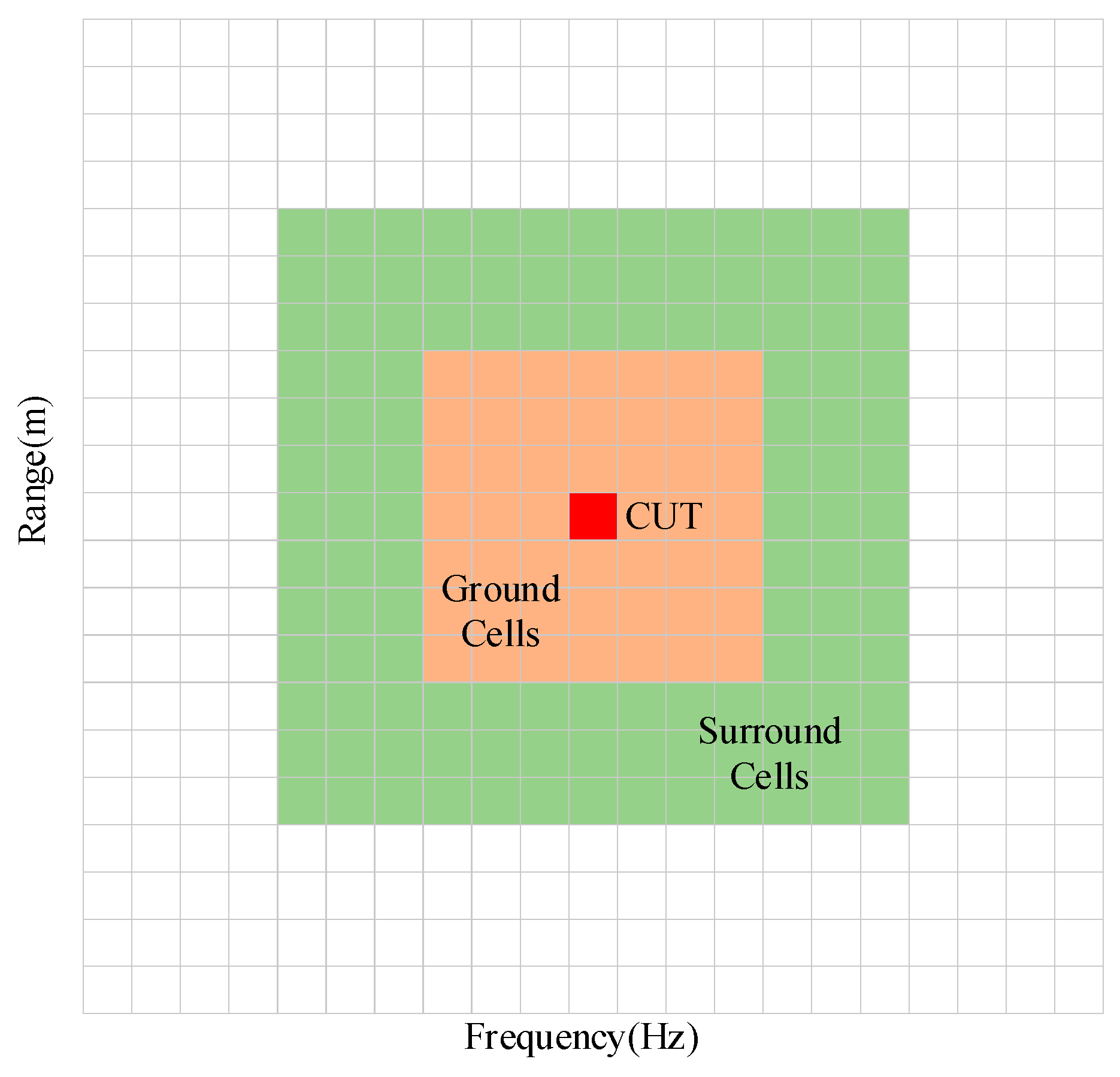
The false alarm rate is determined to calculate the threshold using the average of several neighboring cells around the cell under test (CUT) as a reference. The calculation of the CA-CFAR threshold can be written as:
T = σ Z w h e r e   σ = N ( P f a 1 / N 1 )
where σ is a constant, P f a is a predetermined value of the probability of a false alarm, Z is the average of N neighborhood cells, and N is the number of cells selected around the CUT. Considering that there is a diffusion of vital signals in the distance dimension and the frequency dimension, this study incorporates protection cells to eliminate the effect of leakage. Finally, the location of the detected breath is determined, as shown in Figure 2.

4. Simulation and Analysis

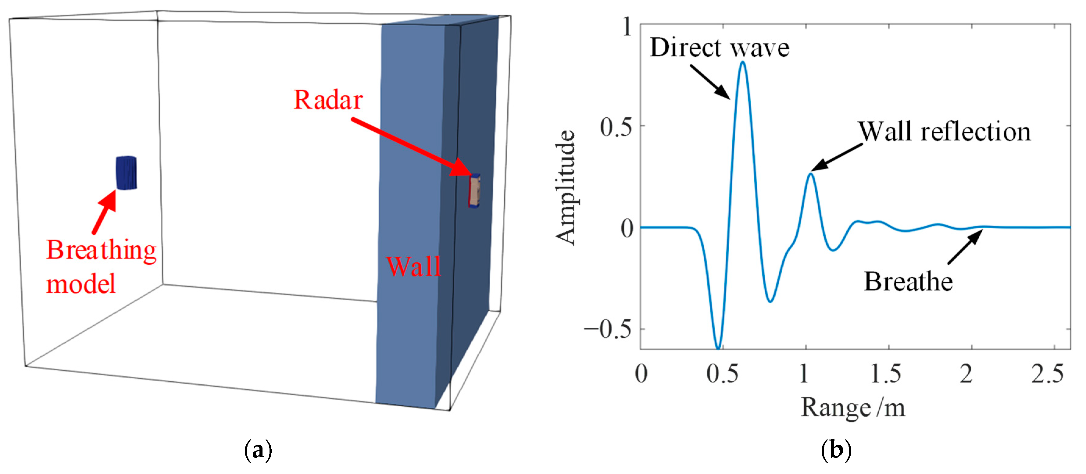
As shown in Figure 3a, we used the simulation software gprMax Version 3.0 to simulate a human breathing scenario [45]. The wall thickness was 24 cm, the relative permittivity was ε r = 6 , the electrical conductivity was σ = 0 . 01   S   m - 1 , and the relative magnetic permeability was μ r = 1 . We used the movement of a metal cylinder to simulate the generation of human chest motion signals, and the radius of the metal cylinder was modulated by a sinusoidal wave with a frequency of 0.18 Hz. The radar was located at a distance of 2.1 m from the center of the metal cylinder. Gaussian white noise was added as an external noise in the simulation. The waveform received by the radar is shown in Figure 3b and the dimension of the simulation data matrix was 5454 × 256 . The slow time sampling rate in the simulation was 4 Hz.
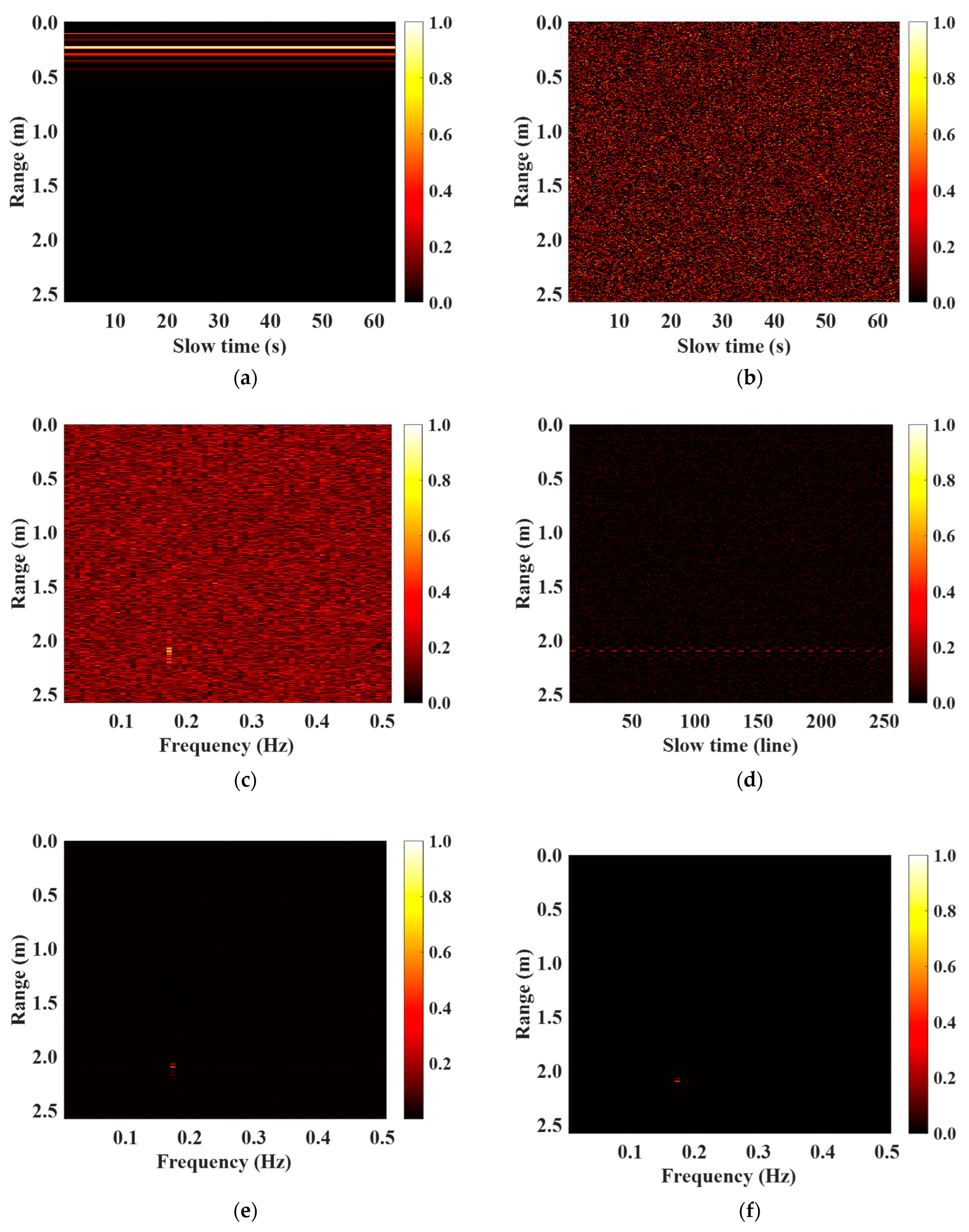
After the simulation in GprMax, we processed the echo signal according to the steps. The results are shown in Figure 4. It can be seen in Figure 4e that the vital signal part was clearly visible after the LRBSD algorithm. Figure 4f shows that the vital signals could be easily extracted from the results.
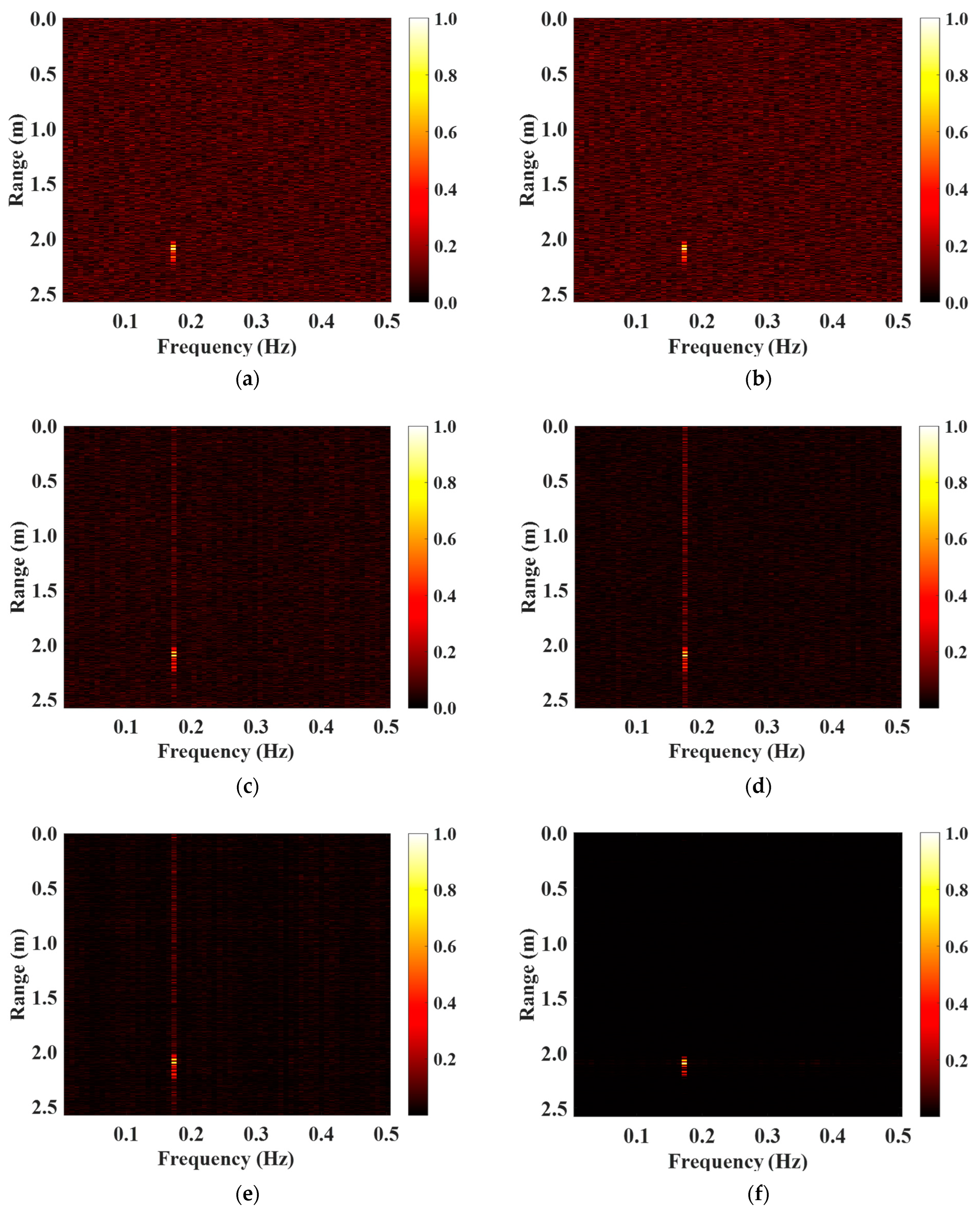
In the identical condition, the LRBSD algorithm suppressed the noise and enhance the vital signals more effectively than other methods. For comparison, we show the results of different processing methods in the same situation in Figure 5. According to the results, it can be seen that the SVD method, the traditional RPCA method, and the decomposition method in [40] had similar performances, and none of them suppressed the noise on the same frequency of vital signals. In Pan’s work [20], the application of the RPCA method in the frequency domain results effectively avoided this problem.
The results of the radar echo matrix after the different processing methods are shown in Figure 5, with an input SNR of 3 dB. The signals were normalized in order to make the presentation more intuitive. The closer the brightness of the target was to the brightness corresponding to the scale value of 1.0, the stronger the target energy obtained. We can see from the Figure 5a that the vital signal obtained by the FFT algorithm was drowned in noise. The performance of AGC method was not much different from that of the FFT method. After processing using the SVD algorithm, the RPCA method, and the BS-RPCA method mentioned in [40], most of the noise was eliminated. However, the noise in the same frequency band as the vital signal still existed. The LRBSD algorithm effectively removed the noise over the whole frequency band. The distance and frequency of the simulation target were hence clearly visible in the results. The target distance was 2.1 m and the breathing frequency was 0.18 Hz. The processing time of the FFT, AGC, SVD, RPCA, BS-RPCA, and LRBSD algorithm were 0.02 s, 0.66 s, 0.27 s, 2.68 s, 1.04 s, and 0.71 s, respectively. The computation times for the different methods were obtained by a computer configured with an AMD Ryzen 5 processor and 32 GB of RAM.
In addition, in view of better analyzing the results processed by the various methods, we introduced the concept of output SNR, SNR out , since in through-the-wall rescue requirements, the frequency of the vital signal is not a significant concern. The vital target location is the critical concern. Therefore, SNR out is expressed as the ratio of the unit value of the signal energy to the unit value of the noise energy above and below the target, labelled as in Equation (48).
( m t , n t ) represents the output position subscript of the target S . A rectangular window is deployed to frame this output location to represent our target location, where R m = 300 , R n = 2 .
SNR out   = 20 log 10 m = m t R m m t + R m k = k t R n k t + R n | S ( m , k ) | 2 R m + 1 2 R k + 1 m = 1 M k = 1 K | S ( m , k ) | m = m t R m m t + R m k = 1 K | S ( m , k ) | M K 2 R m + 1 K
Figure 6 shows the resultant values of SNR out for six different methods with different input SNRs. It can be seen that the LRBSD algorithm performed better than the other algorithms in all SNR cases. Particularly in the interval of −5 dB to 15 dB, the SNR out was more than 18 dB higher than with the other methods. The LRBSD algorithm also has the advantage of low computation cost. From the consumption time provided above, the LRBSD algorithm took less time than RPCA and BS-RPCA and was close to the time of the SVD method. The SNR out of different algorithms in Figure 5 is given in Table 1.

5. Detection Performance in a Through-Wall Situation

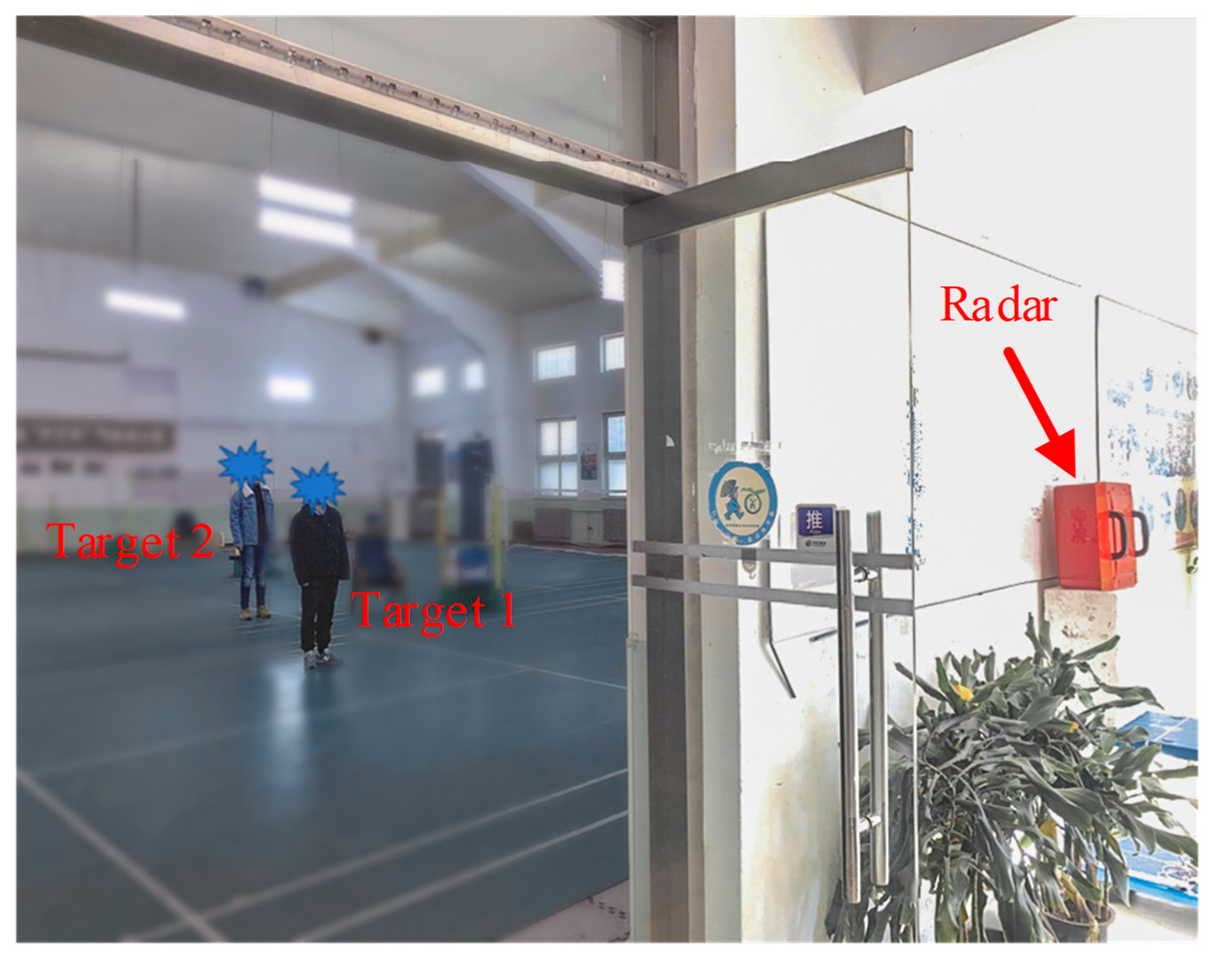
Figure 7 shows the experimental test scenario. The center frequency and bandwidth of the radar used were both 500 MHz. The thickness of the load-bearing reinforced concrete wall was 37 cm. There were two stationary human targets located behind the wall at 7.5 m and 11 m, respectively. The fast time and slow time dimensions of the data matrix collected by the radar in the experiment were 2455 and 512, respectively.
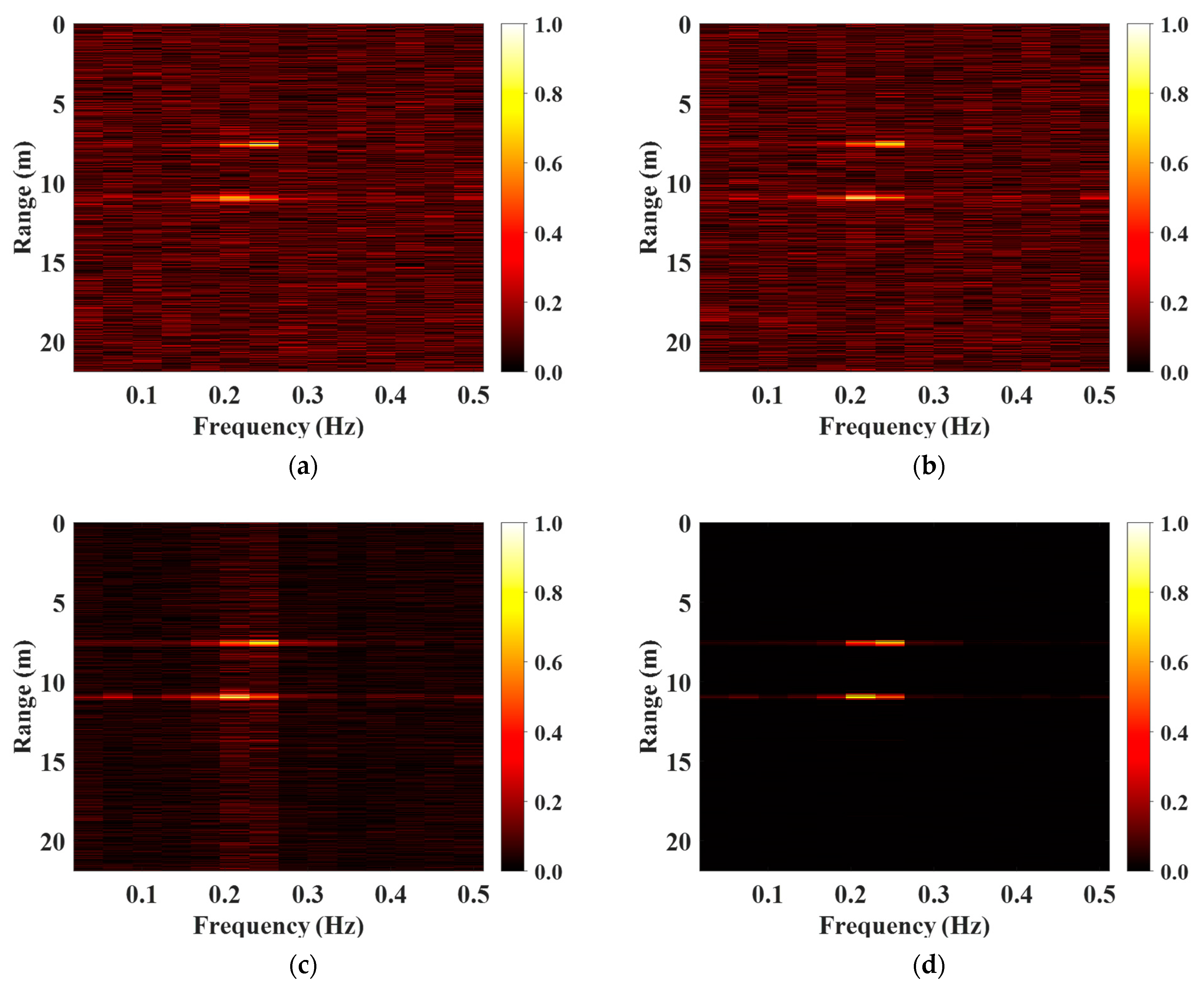
Figure 8 shows the detection results of the four algorithms. In the FFT processing results, the target was covered by noise. in the AGC algorithm processing results, the processing and the noise became average. In the SVD algorithm processing results, the noise was in the same frequency band as the vital signals, making it difficult to identify the target in the distance dimension. The LRBSD algorithm made the two important signal targets clearly visible. The results show that target 1 was located at 7.5 m. Target 2 was positioned at 11 m. Table 2 shows the two targets obtained by the four algorithms. After applying the LRBSD algorithm, the SNR out of targets 1 and 2 were 23.09 dB and 23.85 dB, respectively, which was more than 13 dB higher than all other methods. In this experiment, the running times of the FFT, AGC, SVD, and LRBSD algorithms were 0.015 s, 0.32 s, 0.17 s, and 0.61 s, respectively.
In the experiments of this paper, the radar used was a single transmitter and a single receiver. The distance resolution was determined by the system bandwidth and can be determined according to the following equation:
Δ R = c 2 B
where c is the speed of light, B is the radar bandwidth, and Δ R is the distance resolution. The theoretical bandwidth of the radar was 500 MHz, resulting in a theoretical distance resolution of 0.3 m. However, at the target distance and radar center frequency of this experiment, human targets were not ideal point targets. In practice, human targets are not standard point sources. Thus, the distance resolution of the radar system was reduced. We used a series of experimental data to show that our algorithm could correctly augment two targets when their distance exceeded 2 × Δ R .
The experimental scenario was similar to that in Figure 7. The two targets were located on both sides of the center axis and did not block each other. The distance difference between them and the radar was reduced from 1 m until they were at the same distance.
Figure 9 shows that our proposed algorithm was able to enhance the vital signals without aliasing the targets when the targets were not occluded from each other and the distance was more than 2 × Δ R .
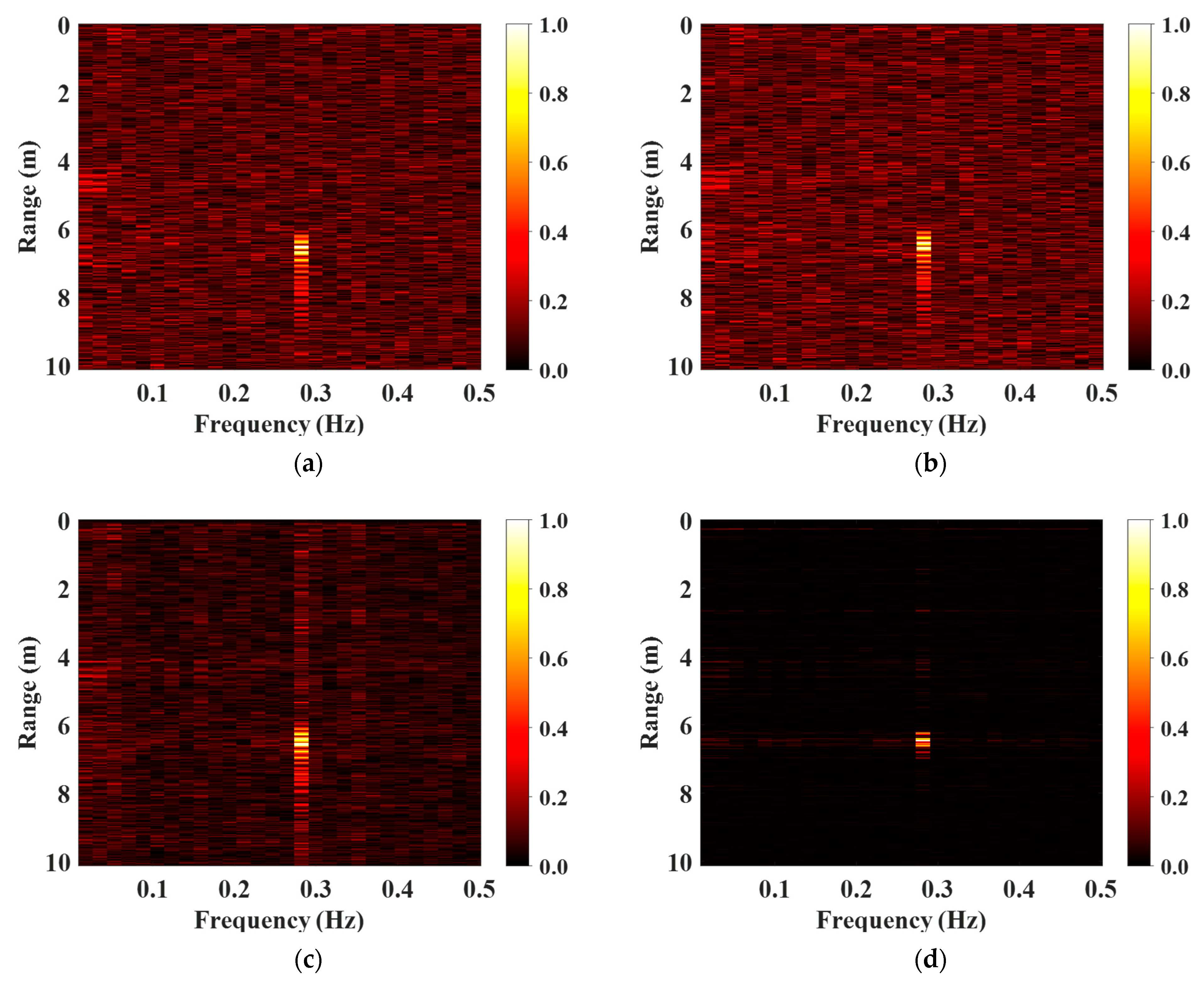
To explore the robustness of the method in different situations, experiments were conducted in a more complex environment to verify the performance of the method. The wall penetrated in the experiment was a composite model consisting of three layers of media. The three layers of media were brick, concrete, and wooden planks, in that order. The thickness of each layer was 30 cm. The standing distance was 6.5 m. Figure 10, showing the experimental scenario, and Figure 11, showing the results of different algorithms, are provided below. The SNR out of the different methods is shown in Table 3.
In this experiment, the running times of the FFT, AGC, SVD, and LRBSD algorithms were 0.014 s, 0.22 s, 0.14 s, and 0.45 s, respectively. In the experiments of this paper, the radar system took about 30 s to acquire the data. The required data processing time was as presented above and the results were obtained in real time.

6. Conclusions

When using UWB impulse radar for through-wall human vital signal detection, the environment and other factors affect the extraction of human breathing signals. In this paper, a time domain echo signal enhancement algorithm based on a low-rank, block-sparse representation is proposed. The algorithm is based on the properties of human vital signals, and ADM is utilized to compute the block-sparse component to obtain a clean vital signal. Random bilateral projection is applied to accelerate the computation. The LRSBD algorithm provides superior denoising results compared to existing algorithms. Intuitive and quantitative results from gprMax simulation and experimental data show that the algorithm is robust to different input SNR, which are significantly higher than with the SVD algorithm. In addition, the method is based on time-domain processing. After the time-domain processing, the previous processing method can be superimposed on the time-frequency signal, which greatly improves the output SNR.

Author Contributions

Conceptualization, X.L. (Xiao Liang); data curation, S.Y., C.S. and G.F.; formal analysis, X.L. (Xiao Liang) and X.L. (Xiaojun Liu); funding acquisition, S.Y. and X.L. (Xiaojun Liu); investigation, X.L. (Xiaojun Liu) and G.F.; methodology, X.L. (Xiao Liang), S.Y., and C.S.; project administration, S.Y. and X.L. (Xiao Liang); resources, S.Y. and G.F.; software, X.L. (Xiao Liang), C.S., and Q.K.; supervision, X.L. (Xiao Liang) and G.F.; validation, X.L. (Xiao Liang), S.Y., C.S., and Q.K.; writing—original draft, X.L. (Xiao Liang); writing—review and editing, S.Y. and C.S. All authors have read and agreed to the published version of the manuscript.

Funding

This research was funded by the research project of the Ministry of Science and Technology under grant 2021YFC3002104 and the National Natural Science Foundation of China under grant 61827803.

Data Availability Statement

The data presented in this study are available on request from the corresponding author. The data are not publicly available due to privacy.

Conflicts of Interest

The authors declare no conflicts of interest.

References

  1. Liu, L.; Fang, G. A Novel UWB Sampling Receiver and Its Applications for Impulse GPR Systems. IEEE Geosci. Remote Sens. Lett. 2010, 7, 690–693. [Google Scholar] [CrossRef]
  2. Le, C.; Dogaru, T.; Nguyen, L.; Ressler, M.A. Ultrawideband (UWB) Radar Imaging of Building Interior: Measurements and Predictions. IEEE Trans. Geosci. Remote Sens. 2009, 47, 1409–1420. [Google Scholar] [CrossRef]
  3. Bernardi, P.; Cicchetti, R.; Pisa, S.; Pittella, E.; Piuzzi, E.; Testa, O. Design, Realization, and Test of a UWB Radar Sensor for Breath Activity Monitoring. IEEE Sens. J. 2014, 14, 584–596. [Google Scholar] [CrossRef]
  4. Chen, T.C.; Liu, J.H.; Chao, P.Y.; Li, P.C. Ultrawideband Synthetic Aperture Radar for Respiratory Motion Detection. IEEE Trans. Geosci. Remote Sens. 2015, 53, 3749–3763. [Google Scholar] [CrossRef]
  5. Liang, X.; Zhang, H.; Ye, S.; Fang, G.; Aaron Gulliver, T. Improved denoising method for through-wall vital sign detection using UWB impulse radar. Digit. Signal Process. 2018, 74, 72–93. [Google Scholar] [CrossRef]
  6. Xue, H.; Liu, M.; Zhang, Y.; Liang, F.; Qi, F.; Chen, F.; Lv, H.; Wang, J.; Zhang, Y. An Algorithm Based Wavelet Entropy for Shadowing Effect of Human Detection Using Ultra-Wideband Bio-Radar. Sensors 2017, 17, 2255. [Google Scholar] [CrossRef] [PubMed]
  7. Lv, H.; Qi, F.; Zhang, Y.; Jiao, T.; Liang, F.; Li, Z.; Wang, J. Improved Detection of Human Respiration Using Data Fusion Basedon a Multistatic UWB Radar. Remote Sens. 2016, 8, 773. [Google Scholar] [CrossRef]
  8. Wu, S.; Tan, K.; Xu, Y.; Chen, J.; Meng, S.; Fang, G. A simple strategy for moving target imaging via an experimental UWB through-wall radar. In Proceedings of the 2012 14th International Conference on Ground Penetrating Radar (GPR), Shanghai, China, 4–8 June 2012; pp. 961–965. [Google Scholar]
  9. Harikesh; Chauhan, S.S.; Basu, A.; Abegaonkar, M.P.; Koul, S.K. Through the Wall Human Subject Localization and Respiration Rate Detection Using Multichannel Doppler Radar. IEEE Sens. J. 2021, 21, 1510–1518. [Google Scholar] [CrossRef]
  10. Liu, L.; Liu, Z.; Barrowes, B.E. Through-Wall Bio-Radiolocation with UWB Impulse Radar: Observation, Simulation and Signal Extraction. IEEE J. Sel. Top. Appl. Earth Obs. Remote Sens. 2011, 4, 791–798. [Google Scholar] [CrossRef]
  11. Liu, L.B.; Liu, M.; Wang, J.Q. Electromagnetic environment comprehension for radar detection of vital signs at China National Training Center for earthquake search & rescue. In Proceedings of the 2016 16th International Conference on Ground Penetrating Radar (GPR), Hong Kong, China, 13–16 June 2016; pp. 1–4. [Google Scholar]
  12. Liang, Z.; Xiong, M.; Chen, J.; Zhao, D.; Yang, D.; Liang, B.; Mo, J. A combined algorithm for non-contact human vital signs monitoring using IR-UWB radar. In Proceedings of the 2023 International Conference on Microwave and Millimeter Wave Technology (ICMMT), Qingdao, China, 14–17 May 2023; pp. 1–3. [Google Scholar]
  13. Guo, S.; Cui, G.; Kong, L.; Song, Y.; Yang, X. Multipath Analysis and Exploitation for MIMO Through-the-Wall Imaging Radar. IEEE J. Sel. Top. Appl. Earth Obs. Remote Sens. 2018, 11, 3721–3731. [Google Scholar] [CrossRef]
  14. Wang, Y.; Yang, Z.; Han, L.; Li, Y.; Zhang, C. Extraction of Vital Sign Based on Improved Complete Ensemble Empirical Mode Decomposition with Adaptive Noise for UWB radar. In Proceedings of the 2023 IEEE 6th International Electrical and Energy Conference (CIEEC), Hefei, China, 12–14 May 2023; pp. 2829–2834. [Google Scholar]
  15. Hassan, S.I.; Zia, M.Y.I.; Otero, P. Identification of Humans in a Disaster using Radio Frequency Technique. In Proceedings of the 2023 Global Conference on Wireless and Optical Technologies (GCWOT), Malaga, Spain, 24–27 January 2023; pp. 1–4. [Google Scholar]
  16. Hosseini, S.M.A.T.; Amindavar, H.; Amirmazlaghani, M. A New Robust Vital Sign Detection in Complex Environments Using Ultrawideband Radar. IEEE Trans. Geosci. Remote Sens. 2016, 54, 6771–6782. [Google Scholar] [CrossRef]
  17. Xu, Y.; Dai, S.; Wu, S.; Chen, J.; Fang, G. Vital Sign Detection Method Based on Multiple Higher Order Cumulant for Ultrawideband Radar. IEEE Trans. Geosci. Remote Sens. 2012, 50, 1254–1265. [Google Scholar] [CrossRef]
  18. Le, M.; Luong, V.S.; Nguyen, K.D.; Le, T.D.; Le, D.K. Multivariate Signal Decomposition for Vital Signal Extraction using UWB Impulse Radar. In Proceedings of the 2023 IEEE Statistical Signal Processing Workshop (SSP), Hanoi, Vietnam, 2–5 July 2023; pp. 290–294. [Google Scholar]
  19. Kocur, D.; Porteleky, T.; Švecová, M.; Švingál, M.; Fortes, J. A Novel Signal Processing Scheme for Static Person Localization Using M-Sequence UWB Radars. IEEE Sens. J. 2021, 21, 20296–20310. [Google Scholar] [CrossRef]
  20. Pan, T.; Guo, Y.; Guo, W.; Kang, C. Detection of Vital Sign Based on UWB Radar by a Time Domain Coherent Accumulation Method. IEEE Sens. J. 2023, 23, 17054–17063. [Google Scholar] [CrossRef]
  21. Nezirovic, A. Stationary clutter- and linear-trend suppression in impulse-radar-based respiratory motion detection. In Proceedings of the 2011 IEEE International Conference on Ultra-Wideband (ICUWB), Bologna, Italy, 14–16 September 2011; pp. 331–335. [Google Scholar]
  22. Mostafa, M.H.; Chamaani, S.; Sachs, J. Singular Spectrum Analysis-Based Algorithm for Vitality Monitoring Using M-Sequence UWB Sensor. IEEE Sens. J. 2020, 20, 4787–4802. [Google Scholar] [CrossRef]
  23. Gore, A.D.; Nair, J.; Bynam, K.; Young-Jun, H.; ChangSoon, P. AGC and DCOC algorithms for sliding IF non-coherent ULP wireless receiver. In Proceedings of the 2016 13th IEEE Annual Consumer Communications & Networking Conference (CCNC), Las Vegas, NV, USA, 9–12 January 2016; pp. 780–784. [Google Scholar]
  24. Rovňaková, J.; Kocur, D. Weak signal enhancement in radar signal processing. In Proceedings of the 20th International Conference Radioelektronika 2010, Brno, Czech Republic, 19–21 April 2010; pp. 1–4. [Google Scholar]
  25. Nanzer, J.A. A Review of Microwave Wireless Techniques for Human Presence Detection and Classification. IEEE Trans. Microw. Theory Tech. 2017, 65, 1780–1794. [Google Scholar] [CrossRef]
  26. Cao, L.; Wei, R.; Zhao, Z.; Wang, D.; Fu, C. A Novel Frequency-Tracking Algorithm for Noncontact Vital Sign Monitoring. IEEE Sens. J. 2023, 23, 23044–23057. [Google Scholar] [CrossRef]
  27. Lai, C.P.; Narayanan, R.M.; Ruan, Q.; Davydov, A. Hilbert-Huang transform analysis of human activities using through-wall noise and noise-like radar. IET Radar Sonar Navig. 2008, 2, 244–255. [Google Scholar] [CrossRef]
  28. Rane, S.A.; Gaurav, A.; Sarkar, S.; Clement, J.C.; Sardana, H.K. Clutter suppression techniques to detect behind the wall static human using UWB radar. In Proceedings of the 2016 IEEE International Conference on Recent Trends in Electronics, Information & Communication Technology (RTEICT), Bengaluru, India, 20–21 May 2016; pp. 1325–1329. [Google Scholar]
  29. Aybat, N.S.; Iyengar, G. An alternating direction method with increasing penalty for stable principal component pursuit. Comput. Optim. Appl. 2015, 61, 635–668. [Google Scholar] [CrossRef]
  30. St-Charles, P.L.; Bilodeau, G.A.; Bergevin, R. Universal Background Subtraction Using Word Consensus Models. IEEE Trans. Image Process. 2016, 25, 4768–4781. [Google Scholar] [CrossRef]
  31. Vaswani, N.; Bouwmans, T.; Javed, S.; Narayanamurthy, P. Robust Subspace Learning: Robust PCA, Robust Subspace Tracking, and Robust Subspace Recovery. IEEE Signal Process. Mag. 2018, 35, 32–55. [Google Scholar] [CrossRef]
  32. An, Q.; Wang, S.; Yao, L.; Zhang, W.; Lv, H.; Wang, J.; Li, S.; Hoorfar, A. RPCA-Based High Resolution Through-the-Wall Human Motion Feature Extraction and Classification. IEEE Sens. J. 2021, 21, 19058–19068. [Google Scholar] [CrossRef]
  33. Zhang, Y.; Xia, T. In-Wall Clutter Suppression Based on Low-Rank and Sparse Representation for Through-the-Wall Radar. IEEE Geosci. Remote Sens. Lett. 2016, 13, 671–675. [Google Scholar] [CrossRef]
  34. Chau, G.; Li, Y.L.; Jakovljevic, M.; Dahl, J.; Rodríguez, P. Wall clutter removal in Doppler ultrasound using principal component pursuit. In Proceedings of the 2018 IEEE International Ultrasonics Symposium (IUS), Kobe, Japan, 22–25 October 2018; pp. 1–4. [Google Scholar]
  35. Pan, J.; Ye, S.; Ni, Z.-k.; Shi, C.; Zheng, Z.; Zhao, D.; Fang, G. Enhancement of vital signals based on low-rank, sparse representation for UWB through-wall radar. Remote Sens. Lett. 2022, 13, 98–106. [Google Scholar] [CrossRef]
  36. Liang, X.; Pan, J.; Zheng, Z.; Ye, S.; Liu, X.; Fang, G. Enhancement of vital signals for UWB through-wall radar using nonconvex regularization. Remote Sens. Lett. 2023, 14, 392–401. [Google Scholar] [CrossRef]
  37. Gongguo, T.; Nehorai, A. Robust principal component analysis based on low-rank and block-sparse matrix decomposition. In Proceedings of the 2011 45th Annual Conference on Information Sciences and Systems, Baltimore, MD, USA, 23–25 March 2011; pp. 1–5. [Google Scholar]
  38. Wang, H.; Banerjee, A.; Luo, Z.-Q.T. Parallel Direction Method of Multipliers. In Proceedings of the Neural Information Processing Systems, Montreal, QC, Canada, 8–13 December 2014. [Google Scholar]
  39. Rovnáková, J.; Kocur, D. TOA Estimation and Data Association for Through-Wall Tracking of Moving Targets. J. Wirel. Commun. Netw. 2010, 2010, 420767. [Google Scholar] [CrossRef]
  40. Gao, Z.; Cheong, L.F.; Wang, Y.X. Block-Sparse RPCA for Salient Motion Detection. IEEE Trans. Pattern Anal. Mach. Intell. 2014, 36, 1975–1987. [Google Scholar] [CrossRef]
  41. Combettes, P.L.; Pesquet, J.C. A Douglas–Rachford Splitting Approach to Nonsmooth Convex Variational Signal Recovery. IEEE J. Sel. Top. Signal Process. 2007, 1, 564–574. [Google Scholar] [CrossRef]
  42. Wei, L.; Wijnholds, S.J.; Hurley, P. Robust recovery for aperture synthesis imaging. In Proceedings of the 2017 IEEE International Conference on Image Processing (ICIP), Beijing, China, 17–20 September 2017; pp. 3570–3574. [Google Scholar]
  43. Zhou, T.; Tao, D. Bilateral random projections. In Proceedings of the 2012 IEEE International Symposium on Information Theory Proceedings, Cambridge, MA, USA, 1–6 July 2012; pp. 1286–1290. [Google Scholar]
  44. Putra, B.; Kurniawan, D. Neural network-based adaptive selection CFAR for radar target detection in various environments. Int. J. Intell. Syst. Technol. Appl. 2019, 18, 377. [Google Scholar]
  45. Warren, C.; Giannopoulos, A.; Giannakis, I. gprMax: Open source software to simulate electromagnetic wave propagation for Ground Penetrating Radar. Comput. Phys. Commun. 2016, 209, 163–170. [Google Scholar] [CrossRef]
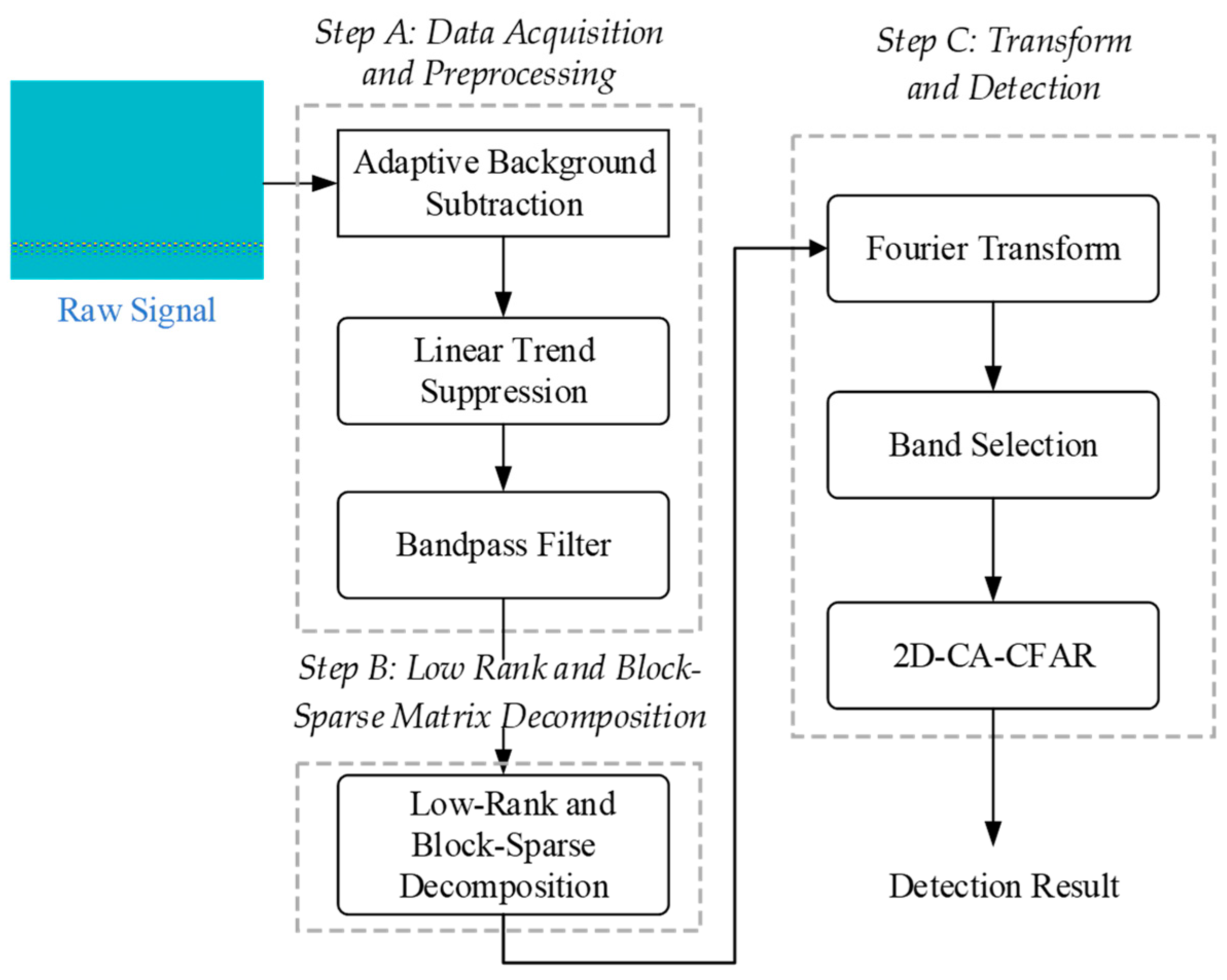
Figure 1. Flowchart of the LRBSD algorithm.
Remotesensing 16 00620 g001
Figure 2. Two-dimensional CA-CFAR applied in the proposed method.
Remotesensing 16 00620 g002
Figure 3. (a) Simulation scenario diagram, (b) waveforms received by the radar.
Remotesensing 16 00620 g003
Figure 4. Result plots: (a) received signal, (b) after preprocessing, (c) frequency domain result of (b), (d) time-domain result of the LRBSD algorithm result processing, (e) frequency domain result of (d), (f) final 2D-CFAR result.
Remotesensing 16 00620 g004
Figure 5. 2 Simulation results: (a) the result obtained by the FFT algorithm, (b) the result obtained by the AGC algorithm, (c) the result obtained by the SVD algorithm, (d) the result obtained by the RPCA algorithm, (e) the result obtained by the BS-RPCA algorithm, (f) the result obtained by the proposed LRBSD algorithm.
Remotesensing 16 00620 g005
Figure 6. Output SNR at different input SNRs obtained by six algorithms.
Remotesensing 16 00620 g006
Figure 7. Experiment 1 scene.
Remotesensing 16 00620 g007
Figure 8. Experimental 1 results: (a) the result obtained by the FFT algorithm, (b) the result obtained by the AGC algorithm, (c) the result obtained by the SVD algorithm, (d) the result obtained by the proposed LRBSD algorithm.
Remotesensing 16 00620 g008
Figure 9. Experimental results: (a) the result obtained by the FFT algorithm when the distance between the two targets was 1 m, (b) the result obtained by the FFT algorithm when the distance between the two targets was 0.6 m, (c) the result obtained by the FFT algorithm when the distance between the two targets was 0.4 m, (d) the result obtained by the proposed LRBSD algorithm based on (a), (e) the result obtained by the proposed LRBSD algorithm based on (b), (f) the result obtained by the proposed LRBSD algorithm based on (c).
Remotesensing 16 00620 g009
Figure 10. Experiment 2 scene.
Remotesensing 16 00620 g010
Figure 11. Experimental 2 results: (a) the result obtained by the FFT algorithm, (b) the result obtained by the AGC algorithm, (c) the result obtained by the SVD algorithm, (d) the result obtained by the proposed LRBSD algorithm.
Remotesensing 16 00620 g011
Table 1. Output SNR (dB) obtained using different algorithms in the simulation result.
AlgorithmSNR (dB)
FFT6.51
AGC6.72
SVD12.15
RPCA16.77
BS-RPCA17.01
LRBSD36.35
Table 2. Output SNR (dB) obtained using different algorithms in the experimental 2 result.
AlgorithmTarget 1 (dB)Target 2 (dB)
FFT4.155.01
AGC4.144.98
SVD8.6510.06
LRBSD23.0922.85
Table 3. Output SNR (dB) obtained using different algorithms in the experimental 2 result.
AlgorithmTarget (dB)
FFT2.49
AGC2.59
SVD4.90
LRBSD11.30
Disclaimer/Publisher’s Note: The statements, opinions and data contained in all publications are solely those of the individual author(s) and contributor(s) and not of MDPI and/or the editor(s). MDPI and/or the editor(s) disclaim responsibility for any injury to people or property resulting from any ideas, methods, instructions or products referred to in the content.