Article

Inversion of Sub-Bottom Profile Based on the Sediment Acoustic Empirical Relationship in the Northern South China Sea

1
Key Laboratory of Marine Geology and Metallogeny, First Institute of Oceanography, Ministry of Natural Resources, Qingdao 266061, China
2
Key Laboratory of Submarine Acoustic Investigation Technology and Application of Qingdao (Preparatory), Qingdao 266061, China
3
Shenzhen Institute of Advanced Technology, Chinese Academy of Sciences, Shenzhen 518055, China
4
Laoshan Laboratory, Qingdao 266237, China
*
Author to whom correspondence should be addressed.
Remote Sens. 2024, 16(4), 631; https://doi.org/10.3390/rs16040631
Submission received: 19 December 2023 / Revised: 26 January 2024 / Accepted: 27 January 2024 / Published: 8 February 2024
(This article belongs to the Section Ocean Remote Sensing)

Abstract

:
This study focuses on the inversion of sub-bottom profile (SBP) data in the northern South China Sea using an empirical relationship derived from sediment acoustic data. The sub-bottom profile is primarily utilized for various marine applications, such as geological mapping and resource exploration. In this research, we present a study conducted in the northern slope canyon of the South China Sea. Firstly, we obtained the seabed reflection coefficient from sub-bottom profiles obtained by the autonomous underwater vehicle (AUV) detection system. Secondly, we utilized the acoustic empirical relationship in the northern South China Sea to establish relationship equations between the seabed reflection coefficient and the porosity, density, and average particle size of the sediment at a main frequency of 4 kHz (the AUV shallow profile main frequency). Then, using these equations, we were able to invert the physical parameters such as porosity, density, and average particle size of the seabed surface sediments. Finally, the inverted results are compared and analyzed by using the sediment samples test data. The overall deviation rate of the inverted physical parameters is within the range of ±10% when compared. The inverted results closely match the measured values, accurately reflecting the dynamic changes in the physical properties of seabed surface sediments. Notably, the average grain size is a direct indicator of the sediment particles size with smaller particles found in deeper water. The variation characteristics of sediment physical parameters align well with the variation of sediment types in the canyon, which is consistent with changes in the water depth, topography, and hydrodynamic conditions of the area. This further demonstrates the reliability of the inversion results.

1. Introduction

The seabed surface sediments are located at the interface between the seawater and sedimentary layers. They consist primarily of sand, silt, clay, pore fluid (seawater), and other substances. These sediments are highly susceptible to deformation due to various sedimentation processes, such as wave action, glacier movement after sea level drop, weathering, and erosion [1,2,3]. As a result, they exhibit engineering properties characterized by higher sensitivity, higher compressibility, lower permeability, and lower strength. This leads to the development of various dynamic geological processes, including submarine landslides, turbidity currents, sediment liquefaction, and changes in submarine topography due to erosion and accumulation [4]. To understand the origin, consolidation process, and sedimentary history of marine sediments, as well as determine the spatial distribution characteristics and predict the stability of the seabed sediments, it is crucial to identify the sedimentary characteristics and physical properties of the seabed surface sediments, such as average grain size, sediment density, and particle porosity [5,6]. Additionally, studying these properties helps with comprehending the occurrence mechanism of various geological processes on the seabed [7,8,9]. Ultimately, this knowledge is of great significance for effectively preventing and controlling seabed geological disasters.
Currently, the methods for obtaining physical property parameters of seabed surface sediments mainly include direct measurement [10,11] and acoustic inversion [12,13,14,15,16]. Direct measurement methods face challenges in terms of operational complexity and technical limitations, making it difficult to obtain a comprehensive understanding of submarine sediment characteristics in a specific area in a timely and widespread manner. However, acoustic inversion technology, which relies on acoustic model theory or empirical relationships, offers a rapid and efficient means of assessing the physical property parameters of shallow surface sediments over a wide area. This technology serves as a valuable complement to discrete sampling investigations.
Since the 1950s, scientists, primarily in the United States, have been conducting research on submarine sediments and acoustic parameters such as sound speed and sound attenuation. They have performed numerous tests and statistical analyses to investigate the correlation between acoustic characteristics and the physical and mechanical properties of submarine sediments. As a result, a regression relationship model between geoacoustic parameters and sediment physical parameters has been established [17,18,19]. Over time, the field of marine sediment acoustics has developed a series of theories on acoustic wave propagation in seabed sediments. Notably, the Biot–Stoll model [20,21,22], Buckingham model [23], equivalent sediment density fluid approximation model (EDFM model) [24], Biot model of intergranular jet flow and shear resistance (BICSQS model) [25], and several other submarine acoustic models have been established. These models offer advantages over statistical empirical relationships by considering the seabed sediment as a fluid, elastic solid, or porous elastic medium, allowing for a more accurate description of acoustic wave propagation characteristics. However, there are limitations in studying the acoustic characteristics of local substrates. In contrast, the sediment sound speed prediction formulas established for different sea areas have demonstrated high accuracy in their respective regions [26,27,28].
The South China Sea, located in East Asia, is the southernmost marginal sea in the region. However, the topography of the area is complex with the development of numerous submarine canyons. The water depth in the north slope canyon area ranges from 400 to 2500 m, and it is known for its abundant oil and gas resources [29,30,31]. This area is also prone to submarine landslide disasters, particularly in the submarine canyon area on the continental slope [32,33]. Additionally, the seabed sediments in the northern slope area of the South China Sea exhibit distinct zonation characteristics. The sediments in the shallow water area consist mainly of silty clay and silty sand, while the sediments in the deep-water area, with a water depth greater than 1000 m, are primarily composed of fine-grained clay and silty clay [34,35,36]. Overall, this area experiences significant variations in water depth and high sedimentation rates. It is characterized by strong turbidity currents and mass transport, leading to significant variations in the physical, mechanical, and acoustic properties of the sediments [37]. Therefore, it serves as an ideal area for studying the physical and acoustic properties of seabed surface sediments. Zou et al. conducted a study on the clustering of sediments on the continental slope and continental shelf in the South China Sea [38]. They analyzed the common properties of submarine sediments in this region. Wang et al. performed a physical analysis of three fine-grained sediments in the South China Sea [28]. They measured the high-frequency acoustic characteristics of these sediments and compared their acoustic properties using the Biot–Stoll model. Hou et al. analyzed and measured the acoustic and physical properties of sediments in the laboratory using sediment samples collected in the early stages [16]. They also developed a sound speed prediction model for sediments in the northern South China Sea using deep neural networks (DNNs). This model considered the sediment type and sedimentary environment, providing insights into the influence mechanism of acoustic characteristics of seabed sediments.
Autonomous underwater devices, such as autonomous underwater vehicles (AUVs), have advanced significantly. This has led to increased research interest in using AUVs for marine bathymetric topography and seabed sub-bottom profiling [39,40,41]. AUVs can operate at various depths and are less affected by harsh weather and marine conditions. The data collected by AUVs have higher resolution and less interference from ambient noise compared to shipboard sub-bottom profiling. Consequently, the physical properties of seabed surface sediments inferred from AUV sub-bottom profile data are considered highly reliable. Building upon previous research in the northern South China Sea, this paper utilizes the AUV sub-bottom profiles (SBP) in the northern slope canyon of the South China Sea as well as sampling and testing data of seabed surface sediments in the area. We conducted inversion research on the physical parameters of seabed surface sediments, including density, average particle size, and porosity. The method’s applicability is discussed by comparing the results with measured physical properties at the sampling points. This study provides a new reference for quickly obtaining continuous geological parameters of seabed sediments.

2. Materials and Methods

2.1. Study Area and Geological Background

The study area of this paper is located in the Shenhu Canyon area of the northern slope of the South China Sea (Figure 1). This area has undergone a geological and historical evolution process similar to that of the northern continental margin of the South China Sea [42]. Since the late Oligocene and Early Miocene, the northern continental margin area of the South China Sea has transitioned from the fault depression stage to the tectonic subsidence stage [43]. This has resulted in the formation of marine and continental transition phases and marine sedimentary sequences [44]. The topography of the area is complex with the development of submarine canyons [45]. The sedimentary structure inside the canyon channel is irregular with both U-shaped and V-shaped structures. The valley floor has a gentle topography and a small average slope. Sediments brought by landslides on the canyon side wall are deposited in the valley floor, and some sediments are transported as turbidity currents below the valley floor [46,47]. In the study area, the top area of the submarine canyon is dominated by the current down the direction of the canyon, while the internal area of the canyon has reciprocating currents. The downstream area of the canyon is dominated by the current down the direction of the canyon. Overall, the flow velocity of the tidal current, including the internal tidal current, is larger in the downward direction along the canyon. The near-bottom residual current in the sea area around submarine canyons is dominated by a west-trending residual current [48,49]. The sediment distribution within the channel is disordered, indicating the presence of multi-stage denudation–accumulation processes [50]. Figure 1 depicts the geographical positions within the research area, the sub-bottom profile lines, and the locations of the sampling stations. The sub-bottom profile line spans a distance of 270 km and encompasses 16 sampling stations. The sub-bottom profile data were collected by the HUGIN 1000 AUV system. The HUGIN 1000 AUV, developed in collaboration between Kongsberg Maritime and the Norwegian Defence Research Establishment, is capable of operating in both deep and shallow waters. Its applications include mine countermeasures, rapid environmental assessment, route surveying, anti-submarine warfare, intelligence, surveillance and reconnaissance operations, as well as research, offshore, and hydrographical purposes.
The seabed sediment column samples were collected in February 2015 using a gravity deep-water column sampler aboard the ‘Offshore Oil 708’ vessel. Each sample had a length of 4–6 m. The sampling locations are depicted in Figure 1c. Subsequently, the retrieved samples underwent laboratory analysis, including many tests of the water content, particle size, soil proportion and shear strength. This analysis yielded parameters such as the water content, particle size, wet sediment density, pore ratio, particle sediment density, and shear strength of the samples.

2.2. Method

2.2.1. Calculation of Seabed Reflection Coefficient

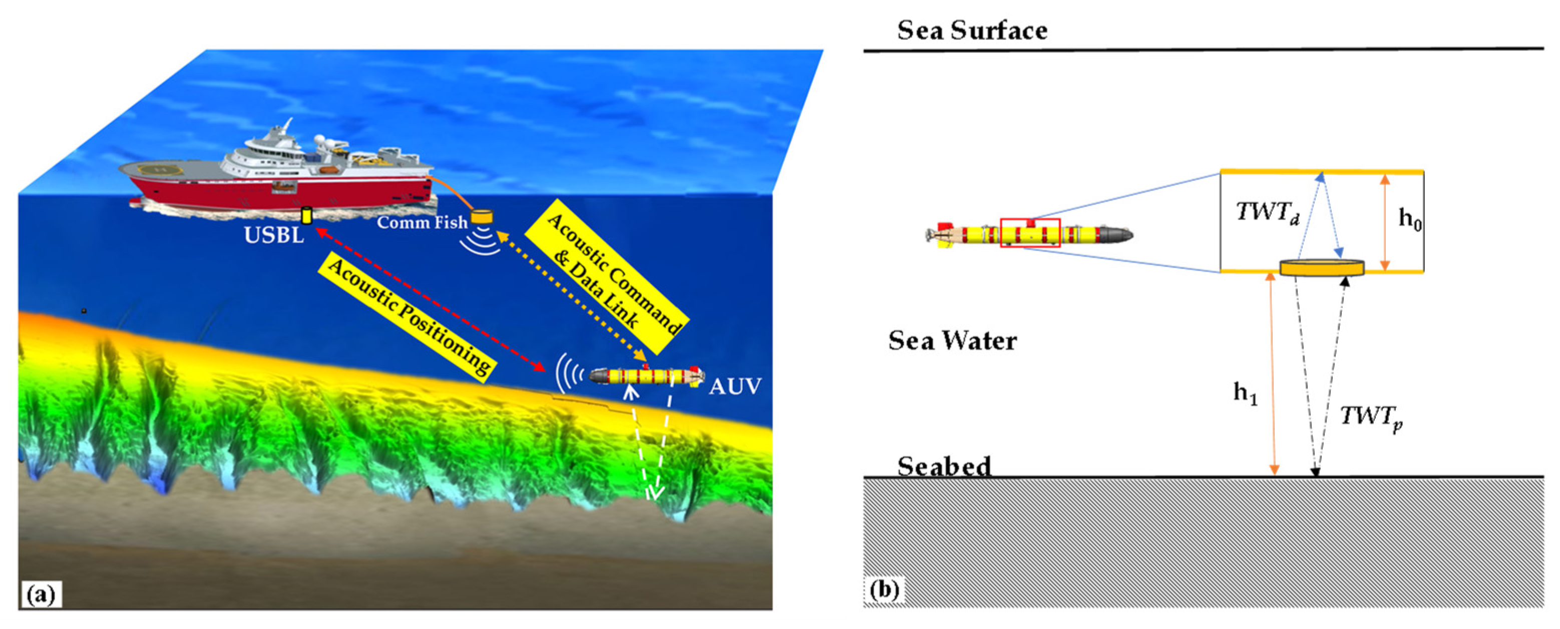
The sub-bottom profile data used in this paper were obtained by the sub-bottom profiler (EdgeTech 2200-M) installed in the HUGIN 1000 AUV system, with a main frequency range of 2–6 kHz and vertical resolution of 6–10 cm. The AUV underwater work and sub-bottom profile detection are shown in Figure 2. Figure 3 shows the frequency band characteristics of this sub-bottom profile data.
The seabed reflection coefficient can be calculated by comparing the amplitude or energy of the reflected waves to that of the incident waves [51,52]. In the case of the seawater/sediment interface, the reflected waves can be directly obtained from the seismic record, while the incident waves need to be calculated using the source signal and depth information. However, most shallow strata profiling systems do not provide the necessary source information. In the AUV shallow formation profile detection system, there is a fixed reflector on the reflection profile due to the gap between the emitted sound source and the AUV shell (Figure 2b). The sound intensity information from this reflector can be approximated to the instantaneous emission intensity. Therefore, the emission coefficient can be calculated based on the reflection intensity of the shell and the reflected waves from the seabed. It is important to note that the actual calculation requires spherical diffusion compensation for the seabed reflected waves.
When sound waves travel through seawater, the wave front can be approximated as a spherical surface centered on the source. As the waves propagate over a greater distance, the spherical surface of the wave front expands, causing the total energy emitted by the source to spread out over a larger area. This leads to a decrease in energy density per unit area and a weakening of the wave’s amplitude. The loss of amplitude due to spherical diffusion is determined by the radius of the wave front in the propagation path, and the seismic record represents the travel time of the wave. In general, speed and time are used to measure distance, so the spherical diffusion loss also depends on the speed and time of propagation. Therefore, to improve the accuracy of sub-bottom profile data, it is necessary to perform wavefront spherical diffusion compensation in conjunction with measurements of bottom reflection waves, their corresponding double travel time, and seawater sound speed. The attenuation factor can be calculated using the following formula:
D = v 0 / v R 2 · t
where D is the attenuation factor, v 0 is the initial speed, v R is root mean square speed of each seawater layer, and t is the double travel time of sound waves. The compensation factor is:
1 / D = v R 2 · t / v 0
Spherical diffusion energy loss is influenced by the radius of the spherical wavefront in the propagation path. The spherical diffusion compensation factor is used to adjust the received signal and compensate for the attenuation loss caused by the spherical diffusion effect on the wave amplitude. Spherical diffusion compensation is a three-dimensional compensation method that theoretically preserves high amplitude. Based on the above theory, the time-varying gain is utilized to counteract the loss of signal energy due to spherical diffusion and formation absorption attenuation. It is employed in digital signal processing based on a pre-designed time-dependent gain curve. The gain curve for compensating spherical diffusion follows a pattern of 10logR, 20logR, and 30logR, where R represents the distance from the transducer (refer to Figure 4). The time, t, is determined by the equation t = R/v, where v is the sound speed. The attenuation loss is measured in dB/m. The time-varying gain curve can be divided into three sections, each with its own definitions for slope and length.
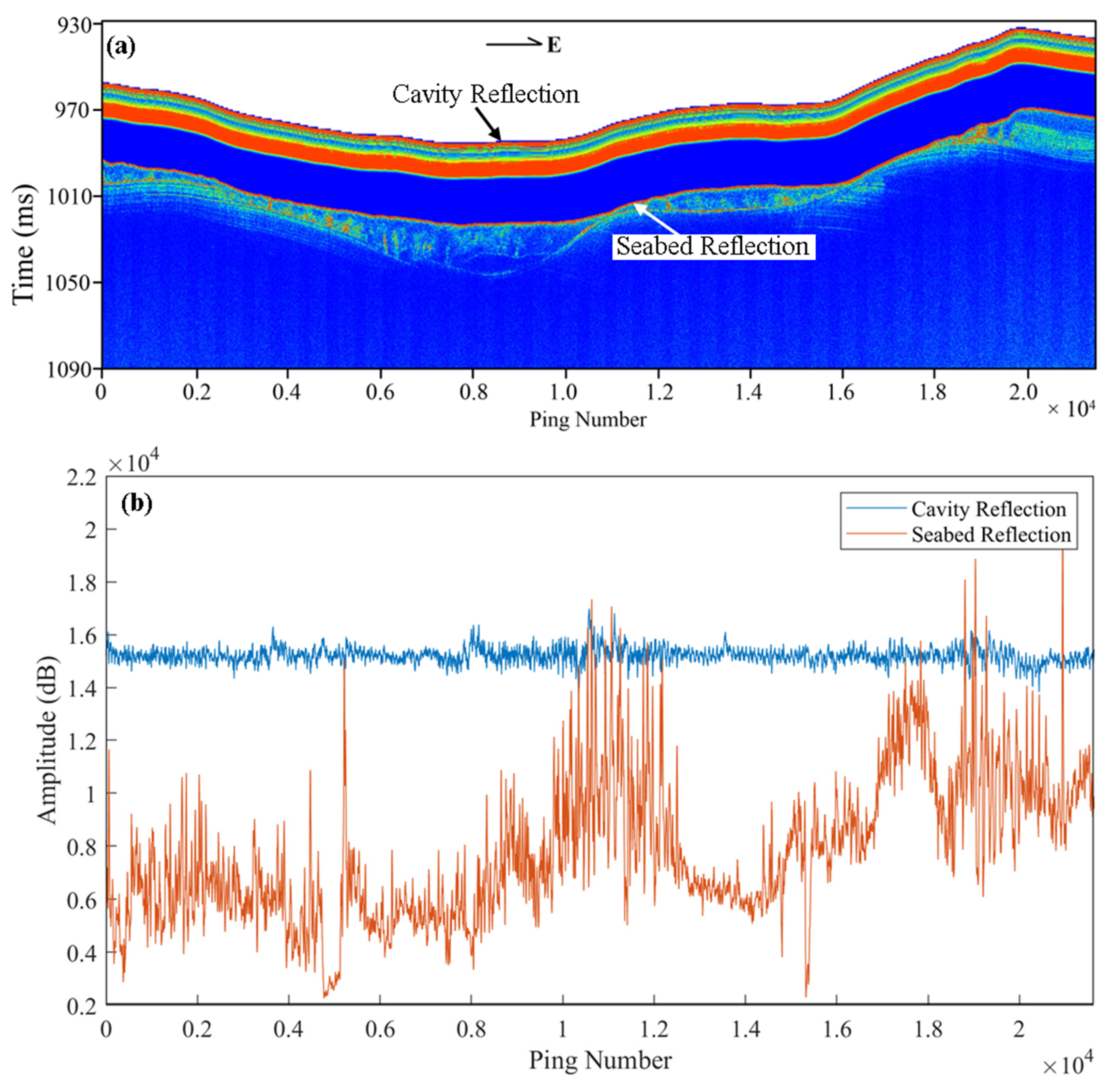
When determining the seabed reflection coefficient, the reflected wave from the AUV cavity can be treated as the incident wave. Additionally, a strong positive reflection is observed in the seabed, and its intensity is closely linked to the seabed reflection coefficient (Figure 5a). Figure 5b illustrates the reflection amplitudes of the cavity and seabed extracted from the sub-bottom profile. Consequently, by analyzing the arrival time and amplitude of the cavity reflection wave and the seabed reflection wave, it is possible to calculate the seabed reflection coefficient ( R S ) using the following formula [53]:
R S = T W T p T W T d A p A d A d r
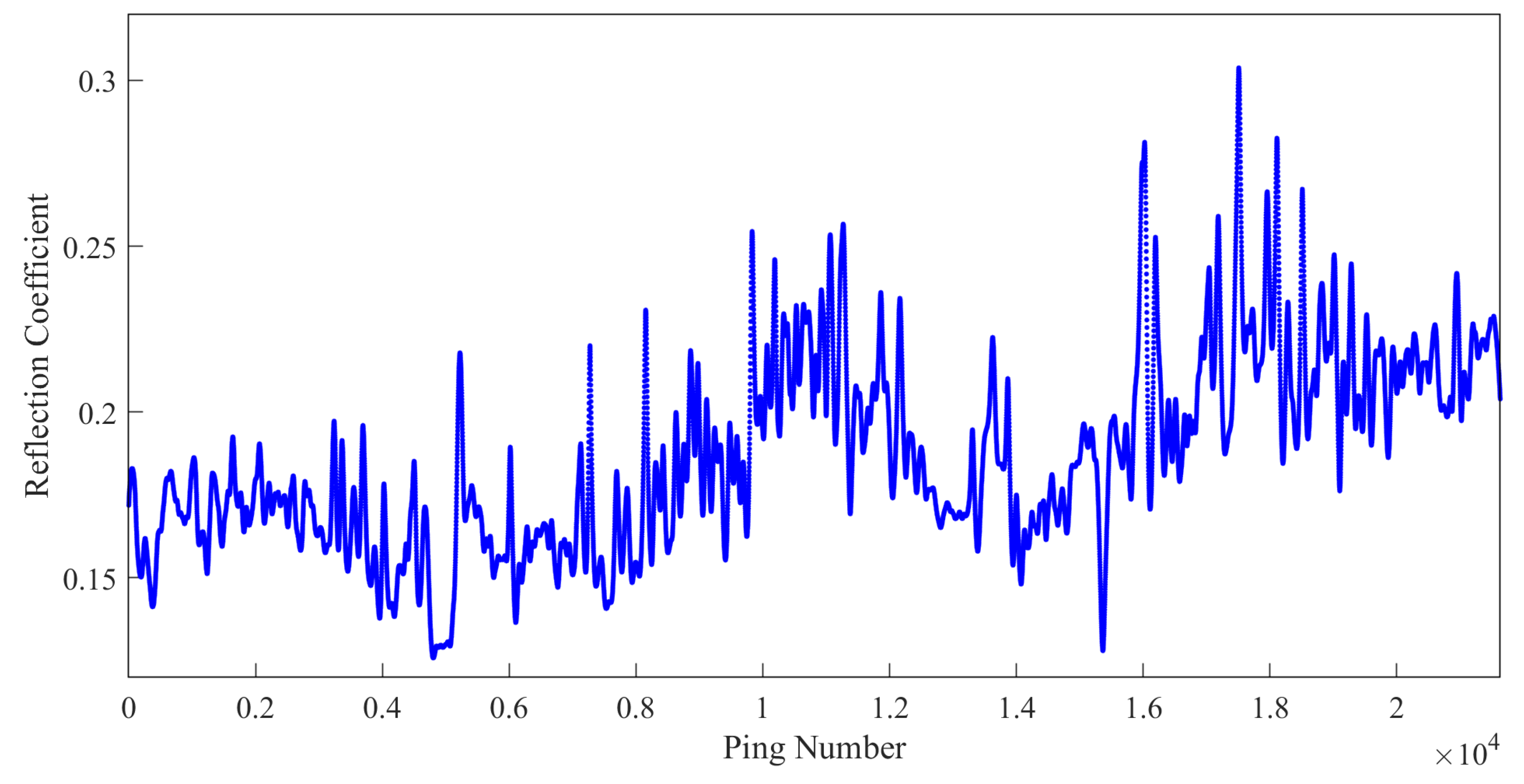
In the equation, A p , A d are the peak amplitudes of the seabed reflected waves and the cavity, respectively; T W T p , T W T d are the corresponding two-way travel times; A d r is the attenuation amplitude of the propagation of sound waves in the water medium. Since the AUV cavity wall reflection is used as the direct wave here, and the distance between the transmitting and receiving system and the cavity wall is very close, the propagation loss is negligible. Therefore, the value is zero. Figure 6 shows the seabed reflection coefficient obtained by using direct wave method to calculate the typical sub-bottom profile.

2.2.2. Establish the Relationship between Seabed Reflection Coefficient and Physical Parameters

The key to inverting the physical properties of the seabed lies in establishing the relationship between acoustic parameters and physical property parameters. In a previous study by Zhou et al., the correlation between seabed reflection coefficient and the physical property parameters of sediment in the northern continental slope of the South China Sea was established using the Biot–Stoll model [54]. According to the Biot–Stoll model, solid particles create an elastic framework that is coupled with pore fluid. Due to the poor cementation among sediment particles and low skeleton modulus, the dissipation of the skeleton is considered to be a significant factor in the attenuation of acoustic wave energy. Unlike fluid viscous dissipation, which varies with frequency, skeleton dissipation remains constant. The 13 parameters involved in the theoretical constitutive equation were determined through testing or curve fitting. However, the inversion process resulted in a large error value.
Both the empirical formula and the acoustic wave propagation theory are used to study the seabed acoustic characteristics such as sound speed and sound attenuation. However, the empirical formula is more convenient and advantageous compared to the acoustic wave propagation theory. The theory of acoustic wave propagation faces challenges in obtaining accurate values for parameters such as tortuosity and particle roughness. Additionally, some parameter values like skeleton modulus are practically impossible to measure. As a result, the acoustic wave propagation theory is constrained in practice, and its prediction ability is limited by the nature of seabed surface sediments. On the other hand, empirical formulas for geoacoustic properties and physical parameters of the seabed are used to verify the accuracy of the acoustic propagation theory or to determine parameter values. Therefore, empirical formulas provide an effective means of establishing the relationship between acoustic properties and physical parameters of the seabed [19]. Therefore, based on the acoustic empirical relationship derived from various sediment sampling and testing data in the northern South China Sea, we conducted a study on the inversion of physical property parameters of the sediment.
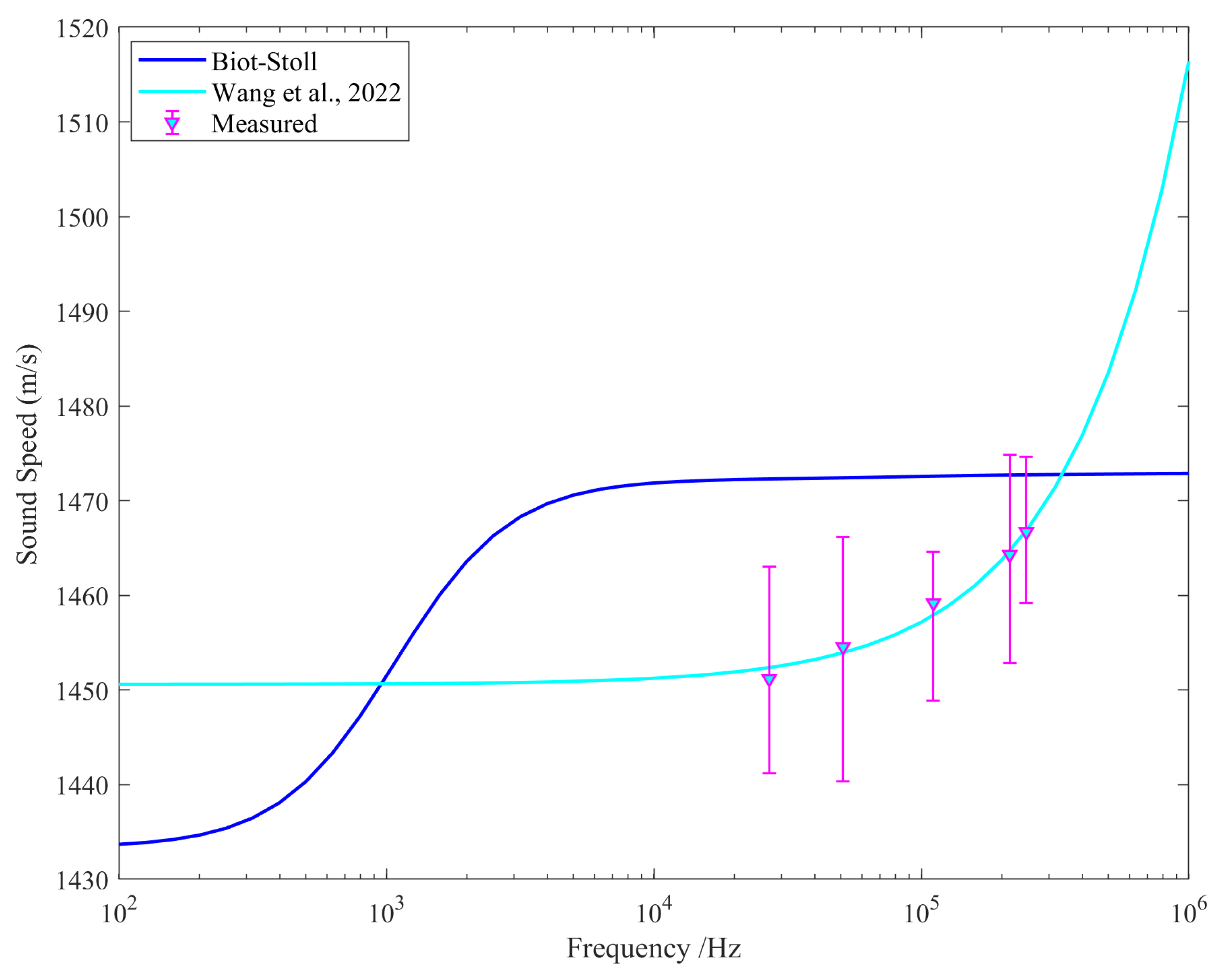
We measured the acoustic properties of three types of fine sediment (silty sand, silt, and silty clay) in the South China Sea using frequencies ranging from 27 to 247 kHz (Table 1). The particle porosity of these sediments ranges from 0.482 to 0.8 with average porosities of 0.482, 0.550, and 0.694 for silty sand, silt, and silty clay. Generally, porosity decreases gradually with increasing particle size. Figure 7 illustrates the comparison between the empirical relation of sound speed of the seabed sediment [28], the sound speed predicted by the Biot–Stoll model, and the measured sound speed. It is evident that there is a significant discrepancy between the measured and predicted values of the Biot–Stoll model. In 2022, Wang et al. established the relationship between sound speed (V) and frequency (f) under different porosity (n) (n = 0.482, 0.550, 0.694), as depicted in Figure 8a. Then, based on the same method and the measured data of the original sample [28], we add some relationships between sound speed and frequency at different porosity (between 0.48 and 0.8); refer to Table 2. Given that the primary frequency of the sub-bottom profile in the study area is approximately 4 kHz, the relationship between the sound speed at 4 kHz and particle porosity can be further established by extracting the particle porosity value under the condition of 4 kHz (V = 2084n2  3194n + 2655, R2 = 0.9975), as shown in Figure 8b.
The density of seawater ( ρ w ) near the seabed is about 1025 kg/m3, and the sound speed of the seawater ( v w ) is about 1530 m/s. The seabed sediment density can be replaced by an equivalent sediment density ( ρ e f f ) [24].
ρ e f f = ρ ρ ρ f 2 ρ + ρ 2 ρ f
ρ = c ρ f n + i F η k ω
where ρ is the volume sediment density, ρ f is the pore fluid sediment density, ω = 2 π f is the angular frequency, c is the tortuosity, n is the particle porosity, i is an imaginary number, F η is a viscosity correction factor used to explain the frequency-dependent viscosity loss of oscillating flow in sediment pores, and k is the complex wave number. The tortuosity c can be replaced by a function of the average grain size Φ:
c = 1.35 Φ 4 0.3 + 0.4125 Φ 4 < Φ < 8 3.0 Φ 8
Bachman [18] presents a regression equation and standard error for particle porosity and mean grain-size data collected in various environments, including the continental shelf and slope, as well as the abyssal plains and hills.
n = 0.208 + 0.0943 Φ 0.00334 Φ 2 ,   σ n = 0.066
Solve (7) for Φ to obtain
Φ = 0.0943 0.0943 2 4 · 0.00334 · ( n 0.208 ) 2 · 0.00334
where Φ , the average grain size, is directly linked to the average grain diameter d m m (millimeter units) by
Φ = l o g 2 d m m
The seabed reflection coefficient R s a m p l e at the sampling point can be calculated according to Rayleigh reflection at normal incidence:
R s a m p l e = v · ρ e f f v w · ρ w v · ρ e f f + v w · ρ w
where the sound speed ( v ) was measured from the sediment samples, v w is the sound speed of sea water, and ρ w is the density of sea water. The sample test data of the sediments, such as porosity, density, average grain size, sediment sound speed and the R s a m p l e , are illustrated in Table 3.
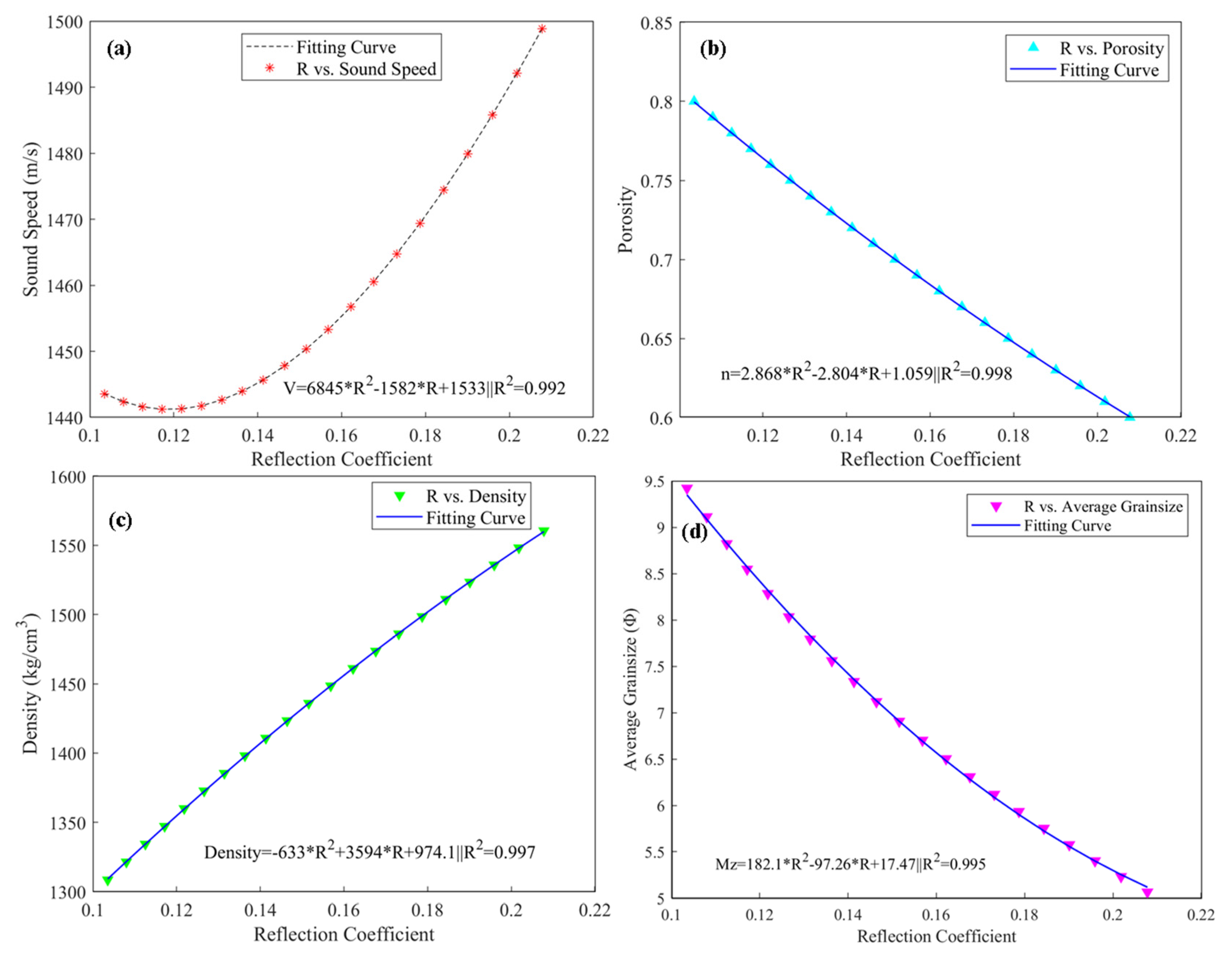
The correlation between seabed reflection coefficient and physical properties such as sound speed, particle porosity, sediment density, and average grain size can be determined (Table 4). This relationship is illustrated in Figure 9. In Figure 9a, the variation of seabed sound speed with the reflection coefficient is shown. The empirical relation of seabed acoustics is used to calculate the reflection coefficient. When the reflection coefficient is small (less than 0.12), there is a negative correlation with the sound speed. However, when the reflection coefficient exceeds 0.12, there is a positive correlation with the sound speed, and the change is rapid. Figure 9b displays the relationship between particle porosity and seabed reflection coefficient. It is observed that particle porosity tends to decrease as the reflection coefficient increases. The particle porosity reflects the sediment density characteristics of the sediment to some extent. A higher particle porosity indicates a higher water content, which in turn leads to a lower sediment density. Consequently, a higher sediment density results in a greater reflection coefficient. This relationship is approximately linear, as depicted in Figure 9c. Furthermore, Figure 9d illustrates the relationship between the average grain size of sediments and seabed reflection coefficient. It is evident that there is a negative correlation between the average grain size and the reflection coefficient. As the reflection coefficient increases, the average grain size decreases. This indicates that the reflection intensity is greater in areas with coarse particles and smaller in areas with fine particles.

3. Results

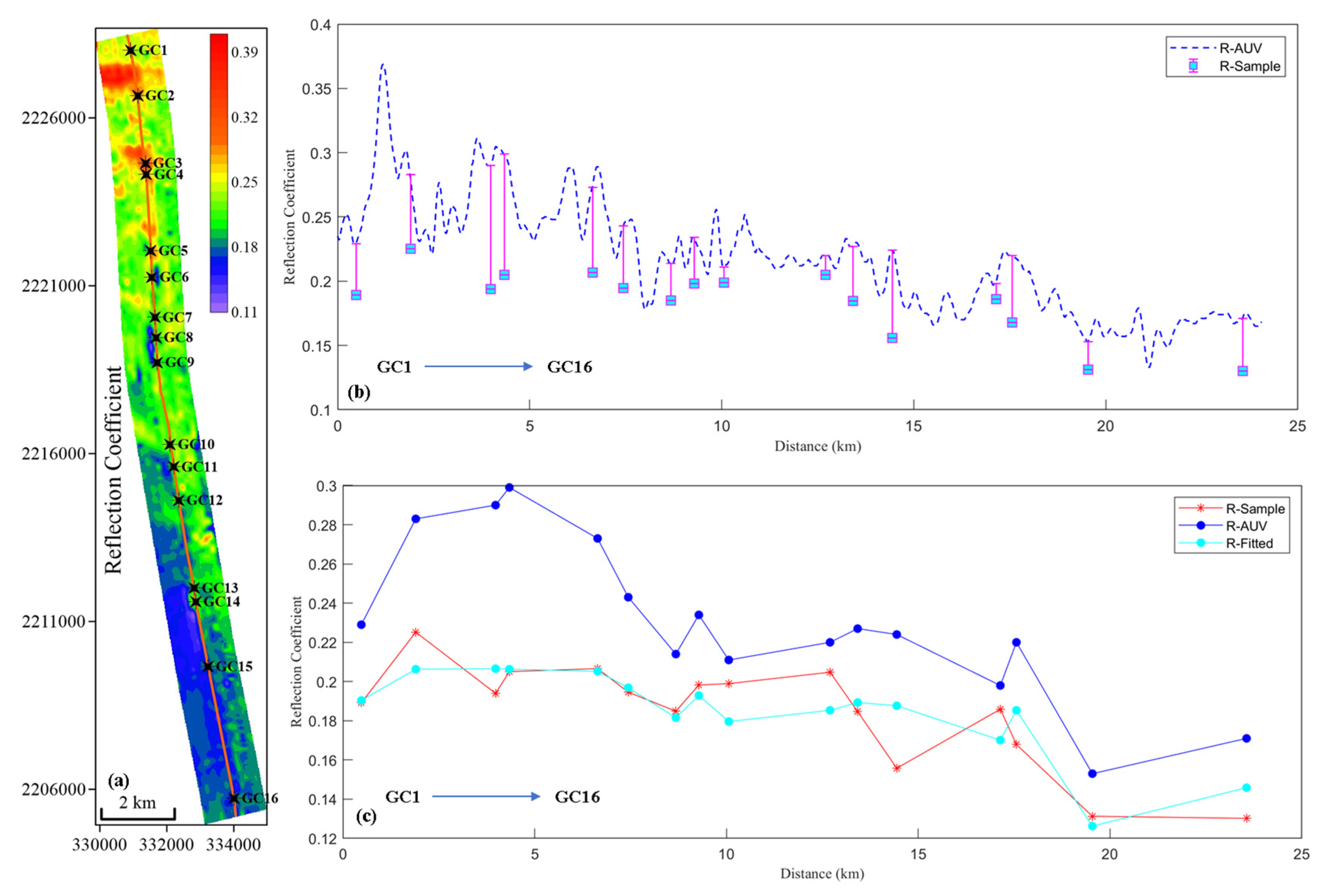
The seabed reflection coefficients of AUV sub-bottom profile data in the study area were calculated using the method in Section 2.2.1 and are shown in Figure 10a. It is observed that the seabed reflection coefficient is highly correlated with the water depth and topography. In the upper area, the reflection coefficient of the shallow water depth is larger, while it decreases with increasing water depth. Different calculation methods yield varying seabed reflection coefficients. To improve the accuracy of the inversion of seabed physical property parameters, the seabed reflection coefficients obtained from sampling test results (Table 3) were compared and analyzed with the reflection coefficients from the sub-bottom profiles (Figure 10b). Some deviations were observed between them. The seabed reflection coefficient values at the sampling points were extracted and compared in detail (Figure 10c), showing a similar variation trend. To enhance the accuracy of the subsequent inversion of sediment physical parameters, a polynomial fitting method is used to fit the seabed reflection coefficient obtained from AUV sub-bottom profiles (R-AUV) to the number range of the seabed reflection coefficient obtained from sampling test (R-Sample, shown in Table 3).
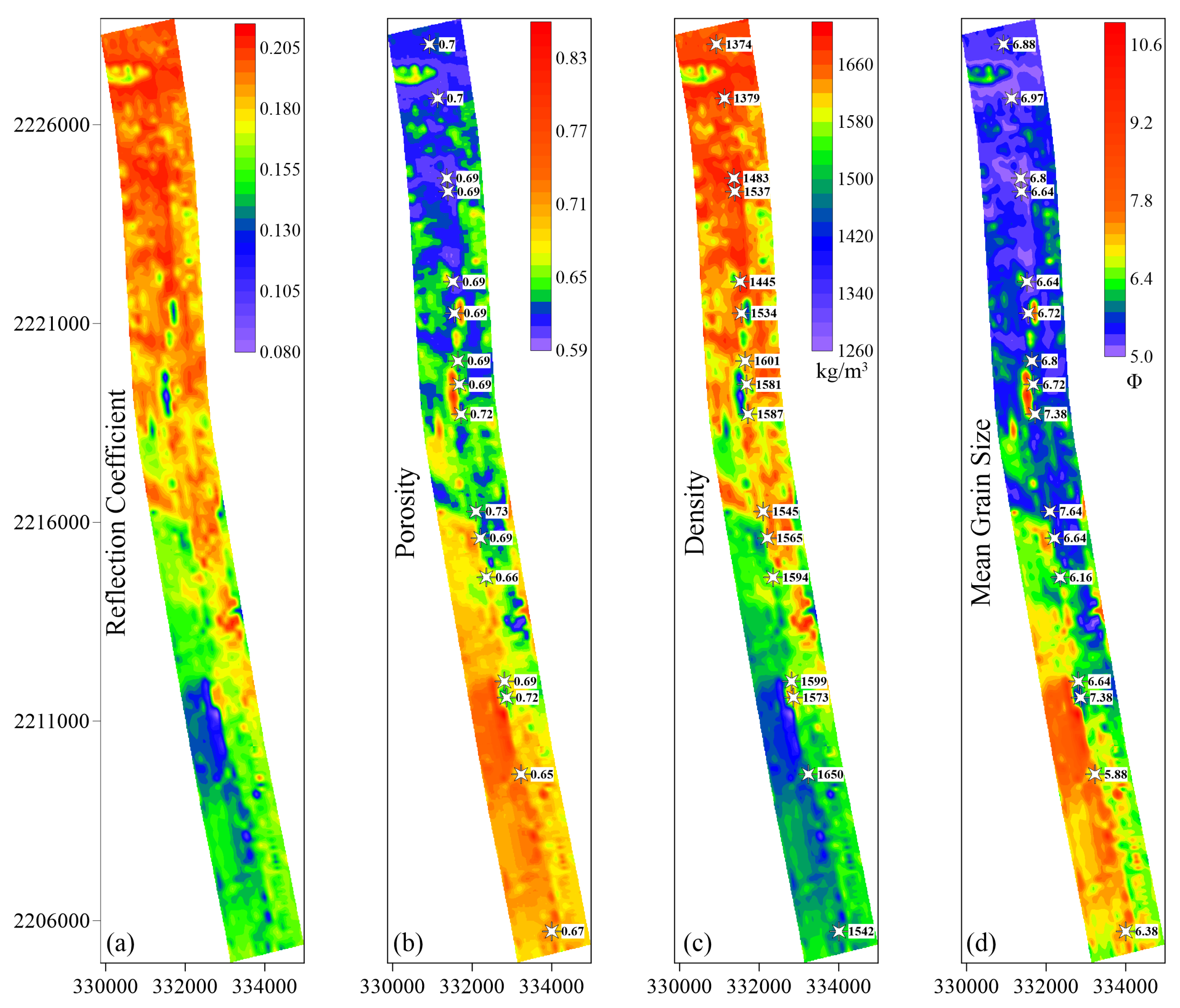
The seabed surface sediments’ physical properties of the study area, including particle porosity, sediment density, and average grain size, were calculated through the seabed reflection coefficient and the empirical relationships in Table 4. Then, using the Kriging interpolation method, the seabed reflection coefficient and the physical parameters are meshed, as depicted in Figure 11.

4. Discussion

4.1. Result Discussion

Through the above calculation process, Figure 12 shows the calculated results of seabed reflection coefficient and the inverted results of physical parameters. Due to certain errors in the acquisition of parameters such as water sound velocity, water density, sediment sound velocity and sediment density, there are differences between the seabed reflection coefficients calculated by the sample test and sub-bottom profiles. Figure 12 shows the seabed reflection coefficients after polynomial fitting. The particle porosity distribution ranges from 0.59 to 0.85 (Figure 12b). The sediment density distribution is primarily concentrated between 1260 and 1700 kg/m3 with an average of approximately 1520 kg/m3 (Figure 12c). The average grain size ranges from 5 to 10.8 Φ, with a maximum of about 10.8 Φ, a minimum of about 5.1 Φ, and an average of about 6.98 Φ (Figure 12d). The study site is situated within a submarine canyon, which is characterized by undulating seabed topography and strong upper hydrodynamic conditions. Turbidity currents and block transport are prevalent, resulting in predominantly coarse-grained silty clay and silty sand sediments. These sediments exhibit low particle porosity and high sediment density, leading to a correspondingly large seabed reflection coefficient. In contrast, the lower hydrodynamic environment experiences reduced sediment transport, resulting in fine-grained clay silt and silty clay sediments with higher pore water content (particle porosity). Consequently, these sediments exhibit lower sediment density and reflection coefficient.
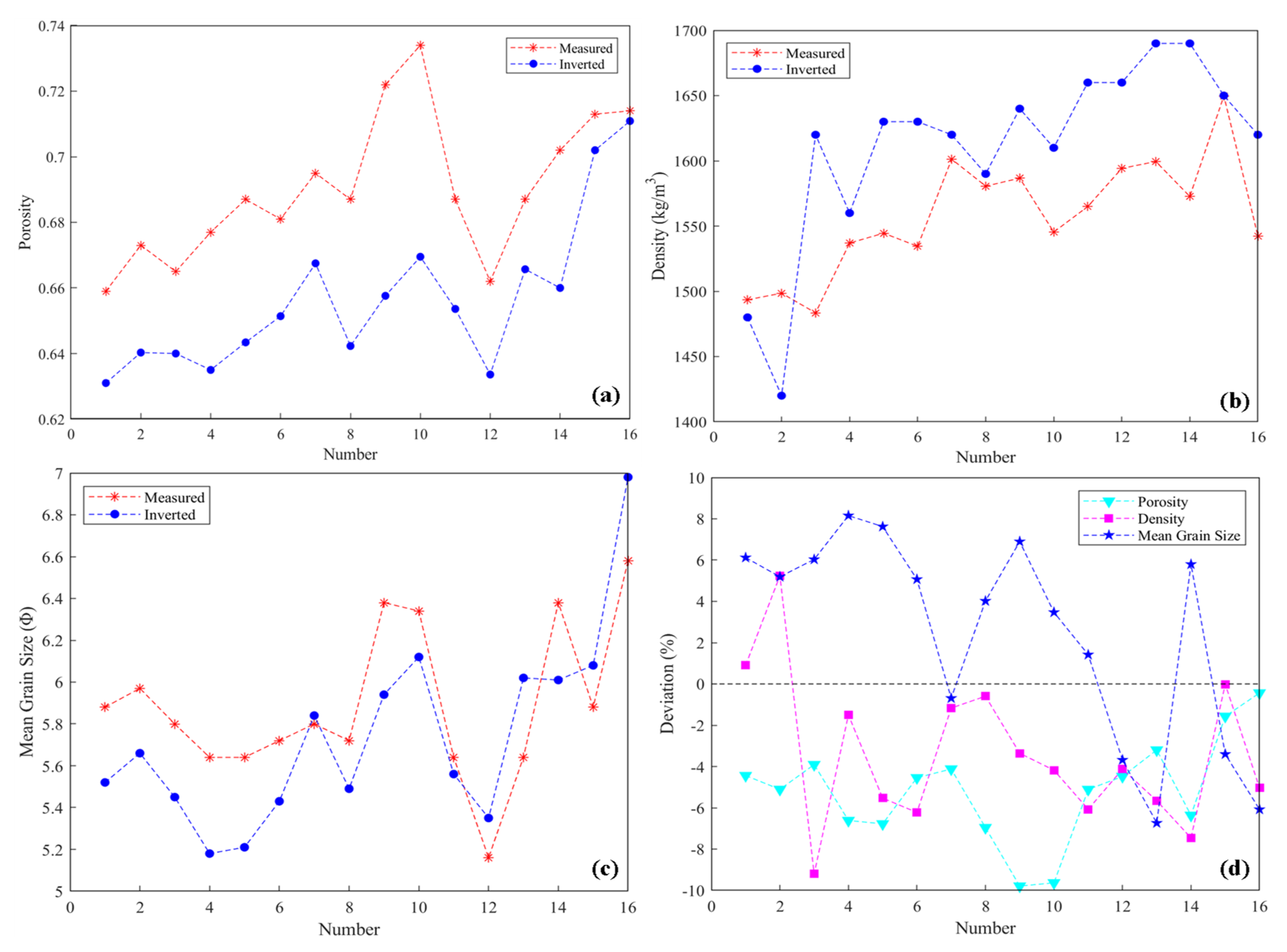
Figure 12 shows the comparison and deviation analysis between the inversion and test results of particle porosity, sediment density, and average grain size at the sampling station.
(1)
The particle porosity inversion results generally exhibit higher values compared to the tested values; the maximum deviation is approx. 0.0645 (Figure 12a). The maximum deviation rate is −8.92%, and the overall deviation ranges from −8.92% to −0.43% (Figure 12d).
(2)
The maximum deviation between the inversion results of seabed sediment density and the sampling test results is approximately 136.53 kg/m3 (Figure 12b). The maximum deviation rate is 9.2%, and the overall deviation rate ranges from −5.24% to 9.2% (Figure 11d).
(3)
The inverted values for average grain size indicate a maximum deviation of approximately −0.46 (unit: Φ) (Figure 12c). The maximum deviation rate is −8.16%, and the overall deviation rate ranges from −8.16% to 6.08% (Figure 12d).
Based on the above analysis, it can be concluded that the inversion results obtained from sub-bottom profiles are in good agreement with the measured values. This suggests that the established correlation between reflection coefficient and physical properties of seabed surface sediments in this area, based on the empirical relationship of sediment acoustic, is reliable.

4.2. Sensitivity Analysis

The empirical relationship model used in this study can only observe the correlation between sediment particle porosity and sound speed. However, it does not provide a way to determine the impact of particle porosity on sound speed and its underlying mechanism. To address this limitation, we propose a method to quantitatively estimate the influence of each parameter on sediment sound speed. In this regard, we adopt an error norm analysis method [55], which defines the random error norm (EN) for analyzing the factors affecting the acoustic characteristics of sediments in the southern South China Sea:
E N = N m e a s u r e d N p r i d i c t e d
In the above formula, EN represents random error, N m e a s u r e d represents the actual measured value of sediment sound speed, and N p r i d i c t e d represents the predicted value of each empirical formula fitted to the sediment in this region. In order to eliminate the error caused by the error norm itself, the relative error norm is introduced, and its definition is as follows:
E N = N m e a s u r e d N p r i d i c t e d N p r i d i c t e d
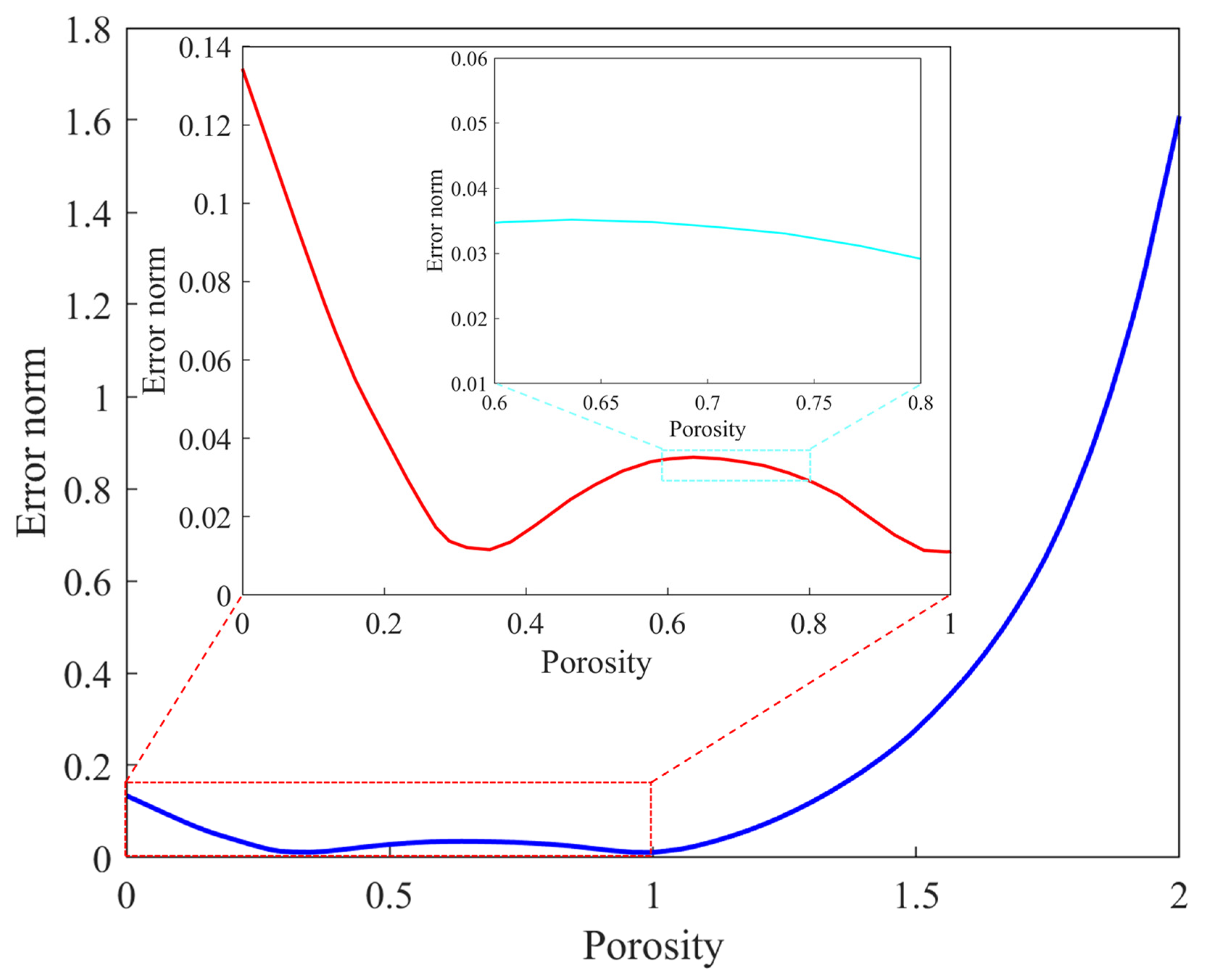
Sensitivity analysis is commonly used in investment projects to quantitatively assess the impact of various factors on a specific variable and analyze the degree of correlation between dependent variables. In this study, we propose applying this method to analyze the influencing factors and mechanisms of sound speed in sediments of the northern slope of the South China Sea. By manipulating the input value of particle porosity in an empirical relationship model, we can compare and analyze the influence of particle porosity on sound speed. Specifically, we input the measured sampling data into the empirical relationship equation, resulting in a set of measured values N m e a s u r e d for the northern slope sediments. By varying the input value of particle porosity within a certain range (0% to 100% of the measured value), we can explore the impact of particle porosity on sound speed. Additionally, we multiply the measured value of particle porosity by (100% to 200%) to expand the range of particle porosity values (0 to 2 times the original measured value). Finally, we substitute the particle porosity values into the empirical relationship equation to obtain a set of predicted sound speed values N p r i d i c t e d for the shallow surface particle porosity of the northern slope of the South China Sea.
The equation V = 2084n2 − 3194n + 2665 represents the relationship between particle porosity and sound speed in the northern slope of the South China Sea. The sensitivity analysis (Figure 13) shows that the sensitivity of particle porosity exhibits an inversed ‘L’ shape. Within the range of 0 to 1, the sensitivity is relatively low, ranging from 0 to 0.14. However, for particle porosity values greater than 1, the sensitivity increases significantly, reaching a maximum value of approximately 1.6. Since the particle porosity values in this study range from 0.6 to 0.8, the sensitivity of the acoustic empirical relation for sediment in the northern South China Sea is relatively small with a variation range of 0.035 to 0.03 and a low rate of change. This suggests that the empirical relation equation established in this study area is reliable.

5. Conclusions

This study examines the reliability of predicting seabed physical property parameters in the South China Sea using sediment acoustics. We collected sub-bottom profile data from the northern region of the South China Sea and determined physical property parameters including the particle porosity, sediment density, and average grain size of the seabed surface sediments in the area. Our findings are as follows:
(1)
We derived an equation that relates the seabed reflection coefficient to sediment particle porosity, sediment density, and average grain size at 4 kHz (the main frequency). The equation showed a high degree of fit with a coefficient of determination R2 greater than 0.99. This equation provides a reliable basis for inverting sediment physical properties using the seabed reflection coefficient.
(2)
We compared the reflection coefficient calculated by the sub-bottom profile with sampled test data and retrieved physical parameters such as particle porosity, sediment density, and average grain size of the seabed surface sediments. The comparative analysis showed that the inversion results had an error range of -8.92% to 9.2%, which is less than 10.0%. In comparison, Zhou et al. achieved an error range within 15% using the Biot–Stoll model [55]. This demonstrates the feasibility and higher accuracy of inverting sediment physical property parameters based on the relation equation of sediment acoustics in our study area compared to general acoustic theoretical models.
(3)
Based on the inversed values, we observed that the seabed reflection coefficient decreased with increasing water depth, corresponding to an increase in sediment particle porosity, a gradual decrease in sediment density, and an increasing trend in average grain size (decreasing sediment particle size). These changes were consistent with variations in sediment type, water depth topography, and hydrodynamic conditions in the area. This finding further confirms the accuracy of the inversion outcomes and introduces a novel approach for indirectly and swiftly obtaining the physical characteristics of seabed sediments.
Overall, our study highlights the potential of using the empirical relationship of sediment acoustics to predict seabed physical property parameters, offering valuable insights for understanding and characterizing submarine sediments.

Author Contributions

Q.Z.: Writing—original draft, Methodology, Software, Investigation, Funding acquisition; X.L. (Xianfeng Li): Writing—original draft, Formal analysis, Resources, Data curation; J.Z.: Writing—review and editing, Visualization; X.L. (Xishuang Li): Writing—review and editing, Conceptualization, Supervision, Validation; G.K.: Writing—review and editing, Supervision, Funding acquisition; B.L.: Writing—review and editing, Project administration. All authors have read and agreed to the published version of the manuscript.

Funding

This study was supported by the National Key R&D Program of China (Grant No. 2021YFF0501200, No. 2021YFF0501201), the Basic Scientific Fund for National Public Research Institutes of China (2021Q03), the Financially supported by Laoshan Laboratory (LSKJ202204803), and the National Natural Science Foundation of China under contracts (No. 42176191).

Data Availability Statement

The data are available from the corresponding author upon request.

Acknowledgments

We are grateful to the CNOOC Research Institute for their help in data processing. We also thank the crew of the ‘Offshore Oil 708’ for the data acquisition and sample collection.

Conflicts of Interest

The authors declare no conflicts of interest.

References

  1. Bao, C. Buride ancient channels and deltas in the Zhujiang River mouth shelf area. Mar. Geol. Quat. Geol. 1995, 15, 25–36. [Google Scholar]
  2. Luan, X.W.; Ran, W.M.; Wang, K.; Wei, X.Y.; Shi, Y.F.; Zhang, H. New interpretation for the main sediment source of the rapidly deposited sediment drifts on the northern slope of the South China Sea. J. Asi. Ear. Sci. 2019, 171, 118–133. [Google Scholar] [CrossRef]
  3. Li, Z.X.; Zeng, Q.B.; Xu, M.; Wang, D.D.; Song, G.Z.; Wang, P.L.; Li, X.J.; Zheng, X. Peat formation and accumulation mechanism in northern marginal basin of South China Sea. Acta Oceanol. Sin. 2021, 40, 95–106. [Google Scholar] [CrossRef]
  4. Zhu, C.Q.; Jia, Y.G.; Zhang, M.S.; Wang, Z.; Shen, Z.; Zhang, B.; Shan, H. Intensity characteristics of surface sediments on continental slope of northern South China Sea. J. Eng. Geo. 2016, 24, 863–870. [Google Scholar] [CrossRef]
  5. Li, Z.Y.; Li, Q. Comprehensive detection device and physical testing for mechanical properties of seabed sediments and shallow gas. J. Phys. Conf. Ser. 2021, 2083, 022105. [Google Scholar] [CrossRef]
  6. Liu, J.; Liu, L.J.; Li, P. Physical-mechanical properties of sediments and their correlation with near seafloor seismic amplitude in the Liwan canyon area, northern South China Sea. Acta Oceanol. Sin. 2023, 42, 130–138. [Google Scholar] [CrossRef]
  7. Zhu, C.Q.; Zhou, L.; Zhang, H.; Cheng, S.; Jiao, X.; Jiang, J.; Shen, Z.; Jia, Y. Preliminary study of physical and mechanical properties of surface sediments in northern South China Sea. J. Eng. Geo. 2017, 25, 1566–1573. [Google Scholar] [CrossRef]
  8. Liu, X.L.; Sun, J.K.; Lu, Y.; Guo, X.S. Control of ambient fluid on turbidity current evolution: Mechanisms, feedbacks and influencing factors. Geosyst. Geoenviron. 2023, 2, 100214. [Google Scholar] [CrossRef]
  9. Dong, Y.K.; Liao, Z.X.; Liu, Q.B.; Cui, L. Potential failure patterns of a large landslide complex in the Three Gorges Reservoir area. Bull. Eng. Geol. Environ. 2023, 82, 41. [Google Scholar] [CrossRef]
  10. Lu, B. Study on sediments and their physical properties in the waters of Dongsha Islands. Acta Oceanol. Sin. 1996, 18, 82–89. [Google Scholar]
  11. Li, G.B.; Wang, J.Q.; Meng, X.M.; Liu, B.H.; Kan, G.M.; Han, G.; Hua, Q.; Pei, Y.; Sun, L. Relationships between the sound speed ratio and physical properties of surface sediments in the South Yellow Sea. Acta Oceanol. Sin. 2021, 40, 65–73. [Google Scholar] [CrossRef]
  12. Zhang, R.H.; Li, F.H. Normal wave theory of beam-shifted sound line for sound propagation in shallow sea. Sci. China Ser. A 1999, 29, 241–251. [Google Scholar]
  13. Chapman, N.R.; Chin-Bing, S.; King, D.; Evans, R.B. Benchmarking geoacoustic inversion methods for range-dependent waveguides. IEEE J. Ocean. Eng. 2003, 28, 320–330. [Google Scholar] [CrossRef]
  14. Peng, Z.H.; Li, Z.L. The effects of sound field by sediment in shallow water. Acoust. Tech. 2004, z1, 7–9. [Google Scholar]
  15. Zhou, J.X.; Zhang, X.Z.; Knobles, D.P. Low-frequency geoacoustic model for the effective properties of sandy seabottoms. J. Acoust. Soc. Am. 2009, 125, 2847–2866. [Google Scholar] [CrossRef] [PubMed]
  16. Hou, Z.Y.; Wang, J.Q.; Li, G.B. A Sound Velocity Prediction Model for Seafloor Sediments Based on Deep Neural Networks. Remote Sens. 2023, 15, 4483. [Google Scholar] [CrossRef]
  17. Hamilton, E.L. Elastic Properties of Marine Sediments. J. Geophy. Res. 1971, 76, 579–603. [Google Scholar] [CrossRef]
  18. Bachman, R.T. Acoustic and physical property relationships in marine sediment. J. Acoust. Soc. Am. 1985, 78, 616–621. [Google Scholar] [CrossRef]
  19. Jackson, D.R.; Richardson, M.D.; Isakson, M.J.; Wilson, P.S. High-Frequency Seafloor Acoustics; Springer: Berlin/Heidelberg, Germany, 2007; Volume 2497. [Google Scholar]
  20. Biot, M.A. Theory of propagation of elastic waves in a fluid-saturated porous solid. I. Low frequency range. J. Acoust. Soc. Am. 1956, 28, 168–178. [Google Scholar] [CrossRef]
  21. Biot, M.A. Theory of propagation of elastic waves in a fluid-saturated porous solid. II. Higher frequency range. J. Acoust. Soc. Am. 1956, 28, 179–191. [Google Scholar] [CrossRef]
  22. Stoll, R.D. Acoustic waves in saturated sediments: In Physics of Sound in Marine Sediments; Hampton, L., Ed.; Plenum: New York, NY, USA, 1974; pp. 19–39. [Google Scholar]
  23. Buckingham, M.J. Theory of compressional and shear waves in fluidlike marine sediments. J. Acoust. Soc. Am. 1998, 103, 288–299. [Google Scholar] [CrossRef]
  24. Williams, K.L. An effective density fluid model for acoustic propagation in sediments derived from Biot theory. J. Acoust. Soc. Am. 2001, 110, 2276–2281. [Google Scholar] [CrossRef] [PubMed]
  25. Chotiros, N.P.; Isakson, M.J. A broadband model of sandy ocean sediments: Biot-Stoll with contact squirt flow and shear drag. J. Acoust. Soc. Am. 2004, 116, 2011–2022. [Google Scholar] [CrossRef]
  26. Kan, G.M.; Su, Y.F.; Li, G.B.; Liu, B.H.; Meng, X.M. The relationship between in-situ acoustic velocity and physical properties of seafloor sediments in the middle of the South Yellow Sea. Acta Oceanol. Sin. 2013, 35, 166–171. [Google Scholar]
  27. Zou, D.P.; Wu, Z.L.; Sun, H.; Liu, W.; Ji, X.R.; Xiao, T.B. Basic geoacoustic structure and geoacoustic model for seafloor sediments. Haiyang Xuebao 2022, 44, 145–155. [Google Scholar] [CrossRef]
  28. Wang, J.Q.; Hou, Z.Y.; Li, G.B.; Kan, G.M.; Liu, B.H.; Meng, X.; Hua, Q.; Sun, L. High-Frequency Dependence of Acoustic Properties of Three Typical Sediments in the South China Sea. J. Mar. Sci. Eng. 2022, 10, 1295. [Google Scholar] [CrossRef]
  29. Ding, W.W.; Li, M.B.; He, M.; Tang, Y.; Fang, Y.X. Cenozoic tectonic sedimentary evolution in the continental shelf-slope area of the north-central south China sea. Geol. J. China Univ. 2009, 15, 339–350. [Google Scholar]
  30. Zhu, L.; Fu, M.Z.; Liu, L.J.; Li, J.; Gao, S. Canyon morphology and sediments on northern slope of the Baiyun Sag. Mar. Geol. Quat. Geol. 2014, 34, 1–9. [Google Scholar] [CrossRef]
  31. Li, X.S.; Zhou, Q.J.; Su, T.Y.; Liu, L.J.; Gao, S.; Zhou, S.W. Slope-confined submarine canyons in the Baiyun deep-water area, northern South China Sea: Variation in their modern morphology. Mar. Geophy. Res. 2016, 37, 95–112. [Google Scholar] [CrossRef]
  32. Liu, L.J.; Fu, M.Z.; Li, J.G.; Li, X.S.; Chen, Y.L.; Gao, S. Geologic Hazards in the Deep Pipeline Routing Area of the Liwan 3-1 Gas Field in the South China Sea. Advan. Mar. Sci. 2014, 3202, 162–174. [Google Scholar]
  33. Zhang, Y.F.; Sun, Z.; Zhang, J.Y.; Wang, L.J. The structure, depositional style and accumulation characteristics of continental margin with diachronous breakup in the northern South China Sea. Int. Geol. Rev. 2019, 62, 1006–1018. [Google Scholar] [CrossRef]
  34. Li, A.X.; Li, Y.H.; Le, G.L. Origin of tellurium anomalies in deep-sea sediments. Acta Geosci. Sin. 2005, 26, 186–189. [Google Scholar]
  35. Liu, J.G.; Xiang, R.; Chen, Z.; Chen, M.H.; Yan, W.; Zhang, L.; Chen, H. Sources, transport and deposition of surface sediments from the South China Sea. Deep. Sea Res. Part I Oceanogr. Res. Pap. 2013, 71, 92–102. [Google Scholar] [CrossRef]
  36. Shi, X.; Liu, S.; Qiao, S.; Liu, Y.; Wang, K. Sediment Type Map of the South China Sea; Science Press: Beijing, China, 2022. [Google Scholar]
  37. Lu, B.; Li, C.X.; Huang, S.J.; Zhang, F. Comparison of acoustic physical properties of shallow seafloor sediments in Yellow Sea, East China Sea and northern South China Sea. Mar. Tech. 2005, 28–33. [Google Scholar]
  38. Zou, D.P.; Wu, B.H.; Lu, B.; Zhang, W.F.; Chen, F.Y. Cluster analysis of acoustic physico-mechanical properties of seafloor sediments. J. Tro. Ocean. 2008, 5, 12–17. [Google Scholar]
  39. Petillot, Y.R.; Reed, S.R.; Bell, J.M. Real Time AUV Pipeline Detection and Tracking Using Side Scan Sonar and Multi-Beam Echosounder. In Proceedings of the Oceans-Conference, Biloxi, MI, USA, 29–31 October 2002; Volume 1, pp. 217–223. [Google Scholar]
  40. Holland, C.W.; Nielsen, P.L.; Dettmer, J.; Dosso, S. Resolving meso-scale seabed variability using reflection measurements from an autonomous underwater vehicle. J. Acoust. Soc. Am. 2012, 131, 1066–1078. [Google Scholar] [CrossRef]
  41. Chotiros, N.P.; Pallayil, V. Seabed characterization using acoustic communication signals on an autonomous underwater vehicle with a thin-line towed array. IEEE J. Ocean. Eng. 2013, 38, 410–418. [Google Scholar] [CrossRef]
  42. Ding, W.; Li, J.; Li, J.; Fang, Y.; Tang, Y. Morphotectonics and evolutionary controls on the Pearl River Canyon system, South China Sea. Mar. Geophys. Res. 2013, 34, 221–238. [Google Scholar] [CrossRef]
  43. Zhu, M.; Graham, S.; Pang, X.; McHargue, T. Characteristics of migrating sub-marine canyons from the middle Miocene to present: Implications for paleoceanographic circulation, northern South China Sea. Mar. Pet. Geol. 2010, 27, 307–319. [Google Scholar] [CrossRef]
  44. Pang, X.; Chen, C.M.; Shao, L.; Wang, C.; Zhu, M.; He, M. Baiyun movement, a great tectonic event on the oligocene-miocene boundary in the northern South China Sea and its implications. Geol. Rev. 2007, 53, 145–151. [Google Scholar]
  45. Su, M.; Lin, Z.X.; Wang, C.; Kuang, Z.; Liang, J.; Chen, H.; Liu, S.; Zhang, B.; Luo, K.; Huang, S.; et al. Geomorphologic and infilling characteristics of the slope-confined submarine canyons in the Pearl River Mouth Basin, northern South China Sea. Mar. Geol. 2020, 424, 106–166. [Google Scholar] [CrossRef]
  46. Wu, S.G.; Qin, Y.S. Study on deep water depositional system of northern continental slope of South China Sea. Acta Sedimentol. 2009, 27, 922–930. [Google Scholar]
  47. Borella, D.R.; de Souza, A.P.; de Almeida, F.T.; de Abreu, D.C.; Hoshide, A.K.; Carvalho, G.A.; Pereira, R.R.; da Silva, A.F. Dynamics of Sediment Transport in the Teles Pires River Basin in the Cerrado-Amazon, Brazil. Sustainability 2022, 14, 16050. [Google Scholar] [CrossRef]
  48. Chao, S.Y.; Shaw, P.T.; Wu, S.Y. Deep water ventilation in the South China Sea. Deep-Sea Res Part I. Oceanogr. Res. Pap. 1996, 43, 445–466. [Google Scholar] [CrossRef]
  49. Tang, D.L.; Sun, Z.; Sui, G.J. Geological environment in the South China Sea. J. Oceanol. Limnol. 2023, 41, 403–408. [Google Scholar] [CrossRef]
  50. Wang, X.; Kneller, B.; Sun, Q. Sediment waves control origins of submarine canyons. Geology 2023, 51, 310–314. [Google Scholar] [CrossRef]
  51. Bull, J.M.; Quinn, R.; Dix, J.K. Reflection Coefficient Calculation from Marine High Resolution Seismic Reflection (Chirp) Data and Application to an Archaeological Case Study. Mar. Geophys. Res. 1998, 20, 1–11. [Google Scholar] [CrossRef]
  52. Yang, Z.; Peng, L.; Zhang, R.W. Method of identifying MTD and BSR through AVO theory. Prog. Geophys. 2018, 33, 1289–1296. [Google Scholar] [CrossRef]
  53. Zheng, J.L.; Xu, J.; Tong, S.Y.; Huang, Y.; Zhou, H. Estimation of seafloor reflectivity in shallow water based on seismic data of sparker sources. Mar. Geophys. Res. 2021, 42, 33. [Google Scholar] [CrossRef]
  54. Zhou, Q.J.; Li, X.S.; Huang, B.G.; Liu, L.J.; Liu, B.; Zhang, C. Inversion of the physical properties of seafloor surface sediments based on AUV sub-bottom profile data in the northern slope of the South China Sea. Sci. Rep. 2021, 11, 6539. [Google Scholar] [CrossRef] [PubMed]
  55. Hou, Z.Y. Acoustic Characteristics and Correlation Analysis of Physical Parameters of Seabed Sediments in the Southern South China Sea. Ph.D. Thesis, University of Chinese Academy of Sciences, Beijing, China, 2016. [Google Scholar]
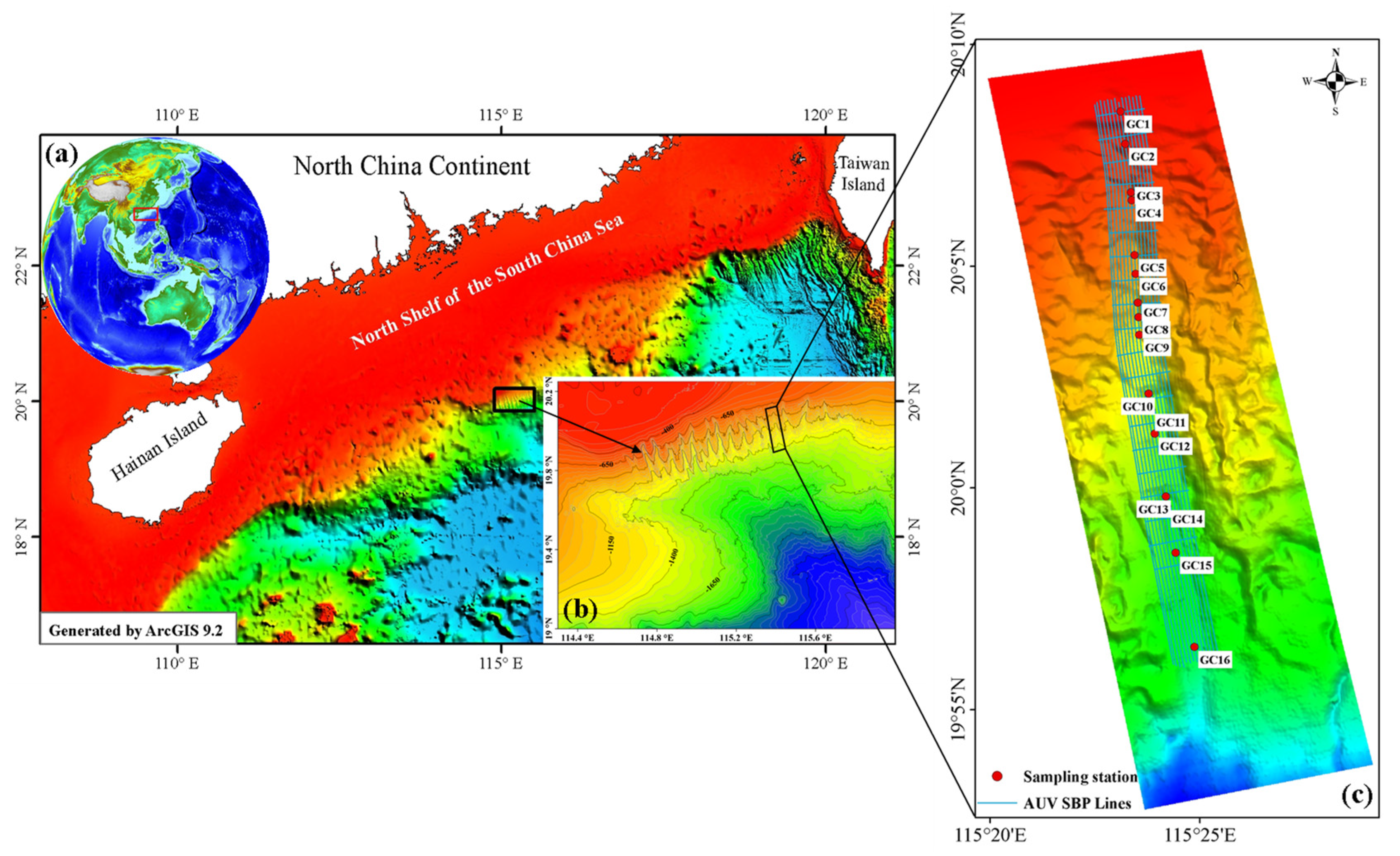
Figure 1. Illustrates the study area, including: (a) a location index map, (b) a map showing water depth and topography of the northern slope canyon in the South China Sea, and (c) a map highlighting the topographic features of the canyon interior. Additionally, the figure also includes the location of the AUV SBP lines and sampling stations.
Remotesensing 16 00631 g001
Figure 2. (a) Schematic diagram of AUV underwater detection, (b) the schematic diagram of AUV sub-bottom profile detection (h0 is the distance between the sound source and the AUV shell, h1 is the distance to the seabed, h1 >> h0).
Remotesensing 16 00631 g002
Figure 3. Spectrum analysis diagram of the sub-bottom profile.
Remotesensing 16 00631 g003
Figure 4. Typical gain curves for spherical diffusion and attenuation losses.
Remotesensing 16 00631 g004
Figure 5. Typical AUV sub-bottom profile (a) and amplitude extraction results (b).
Remotesensing 16 00631 g005
Figure 6. Seabed reflection coefficient calculated by the typical sub-bottom profile.
Remotesensing 16 00631 g006
Figure 7. Comparison of the empirical relationship between the sound speed of the seabed sediments [28], the sound speed of the Biot–Stoll model and the measured sound speed [28] (sediment type is silty clay, particle porosity is 0.694).
Remotesensing 16 00631 g007
Figure 8. Relation between particle porosity and sound speed ((a) empirical relation of sound speed under different particle porosity conditions; (b) change in sound speed with particle porosity at 4 kHz).
Remotesensing 16 00631 g008
Figure 9. Correlation between seabed reflection coefficient and physical property parameters ((a) relation equation between reflection coefficient and sound speed, (b) relation equation between particle porosity and reflection coefficient, (c) relation equation between sediment density and reflection coefficient, (d) relation equation between average grain size and reflection coefficient).
Remotesensing 16 00631 g009
Figure 10. Comparison between the seabed reflection coefficient calculated based on the sub-bottom profile and the measured reflection coefficient at the sample point ((a) the seabed reflection coefficient calculated from the sub-bottom profile; (b) the seabed reflection coefficient of the sample point, the blue dashed line is the seabed reflection coefficient calculated by the sub-bottom profile, and the pink box point is the reflection coefficient calculated by the sampled test data. The positions are shown in (a) as a solid red line and appropriate four-star points. (c) The seabed reflection coefficient value at the sampling point; the blue points are the reflection coefficient calculated of the sub-bottom profile, the red points are the reflection coefficient calculated by the sampled test data, and the cyan points are the reflection coefficient after fitting of the sub-bottom profile).
Remotesensing 16 00631 g010
Figure 11. Inverted physical parameters and the sample test results of the seabed sediments ((a) seabed reflection coefficient; (b) particle porosity; (c) sediment density; (d) average grain size).
Remotesensing 16 00631 g011
Figure 12. Comparison of physical property parameter inversion results ((a) comparison of particle porosity inversion results with measured data; (b) comparison of sediment density inversion results with measured data; (c) comparison of average grain size inversion results with measured data; (d) the uncertainty of inversion results).
Remotesensing 16 00631 g012
Figure 13. Sensitivity analysis of particle porosity (the red and cyan curves are locally enlarged).
Remotesensing 16 00631 g013
Table 1. The measured sound speed at different frequencies.
Sediment TypeRangeSound Speed (m/s)
27 kHz51 kHz111 kHz214 kHz247 kHz
Silty sandMaximum1641.131637.641643.921657.431671.05
Minimum1576.701586.231591.611586.861598.36
Mean1609.171616.431622.471627.381634.16
SiltMaximum1568.661568.771574.621580.101583.05
Minimum1529.861527.961537.801539.121547.14
Mean1546.161550.561555.201560.321565.04
Silty clayMaximum1461.181468.781469.511475.721474.19
Minimum1439.921442.961453.81453.741458.77
Mean1451.191454.561459.201464.301466.70
Table 2. The relationships between sound speed and frequency at different porosity.
Porosity (n)Relationship (V vs. f)
0.48V = 0.0956 f + 1609.5
0.50V = 0.0846 f + 1586.5
0.52V = 0.0832 f + 1568.7
0.55V = 0.0759 f + 1545.6
0.57V = 0.0719 f + 1519.4
0.60V = 0.0699 f + 1493.3
0.63V = 0.0682 f + 1479.7
0.65V = 0.0675 f + 1468.5
0.67V = 0.0663 f + 1459.4
0.69V = 0.0658 f + 1450.6
0.73V = 0.0658 f + 1445.7
0.75V = 0.0642 f + 1442.1
0.78V = 0.0637 f + 1439.8
0.80V = 0.0625 f + 1439.6
Table 3. Sample test data of the sediments ( v w = 1500   m / s , ρ w = 1023   k g / m 3 ).
Station NumberPorosityDensity (kg/m3)Average Gran Size (Φ)Sediments’ Sound Speed (m/s) R s a m p l e
GC10.7013746.881450.64 0.189
GC20.7013796.971449.55 0.225
GC30.6914836.801451.79 0.194
GC40.6915376.641454.31 0.205
GC50.6914456.641454.31 0.207
GC60.6915346.721453.02 0.195
GC70.6916016.801451.79 0.185
GC80.6915816.721453.02 0.198
GC90.7215877.381445.29 0.199
GC100.7315457.641443.37 0.205
GC110.6915656.641454.31 0.185
GC120.6615946.161463.87 0.156
GC130.6915996.641454.31 0.186
GC140.7215737.381445.29 0.168
GC150.6516505.881470.86 0.131
GC160.6715426.381458.96 0.130
Table 4. The empirical relationship between reflection coefficient and seabed parameters.
Empirical RelationshipR-Square
R vs. Sound Speed: V = 6845 R 2 1582 R + 1533 0.992
R vs. Porosity: n = 2.868 R 2 2.804 R + 1.059 0.998
R vs. Density: ρ = 633 R 2 + 3594 R + 974.1 0.997
R vs. Average Grainsize: M z = 182.1 R 2 97.263594 R + 17.47 0.995
Disclaimer/Publisher’s Note: The statements, opinions and data contained in all publications are solely those of the individual author(s) and contributor(s) and not of MDPI and/or the editor(s). MDPI and/or the editor(s) disclaim responsibility for any injury to people or property resulting from any ideas, methods, instructions or products referred to in the content.