Article

A UAV-Based Single-Lens Stereoscopic Photography Method for Phenotyping the Architecture Traits of Orchard Trees

1
Information Department, Beijing University of Technology, Beijing 100022, China
2
Graduate School of Agricultural and Life Sciences, The University of Tokyo, Tokyo 188-0002, Japan
3
Faculty of Food and Agricultural Sciences, Fukushima University, Fukushima 960-1296, Japan
*
Author to whom correspondence should be addressed.
Remote Sens. 2024, 16(9), 1570; https://doi.org/10.3390/rs16091570
Submission received: 23 February 2024 / Revised: 18 April 2024 / Accepted: 21 April 2024 / Published: 28 April 2024

Abstract

:
This article addresses the challenges of measuring the 3D architecture traits, such as height and volume, of fruit tree canopies, constituting information that is essential for assessing tree growth and informing orchard management. The traditional methods are time-consuming, prompting the need for efficient alternatives. Recent advancements in unmanned aerial vehicle (UAV) technology, particularly using Light Detection and Ranging (LiDAR) and RGB cameras, have emerged as promising solutions. LiDAR offers precise 3D data but is costly and computationally intensive. RGB and photogrammetry techniques like Structure from Motion and Multi-View Stereo (SfM-MVS) can be a cost-effective alternative to LiDAR, but the computational demands still exist. This paper introduces an innovative approach using UAV-based single-lens stereoscopic photography to overcome these limitations. This method utilizes color variations in canopies and a dual-image-input network to generate a detailed canopy height map (CHM). Additionally, a block structure similarity method is presented to enhance height estimation accuracy in single-lens UAV photography. As a result, the average rates of growth in canopy height (CH), canopy volume (CV), canopy width (CW), and canopy project area (CPA) were 3.296%, 9.067%, 2.772%, and 5.541%, respectively. The r2 values of CH, CV, CW, and CPA were 0.9039, 0.9081, 0.9228, and 0.9303, respectively. In addition, compared to the commonly used SFM-MVS approach, the proposed method reduces the time cost of canopy reconstruction by 95.2% and of the cost of images needed for canopy reconstruction by 88.2%. This approach allows growers and researchers to utilize UAV-based approaches in actual orchard environments without incurring high computation costs.

1. Introduction

The canopy architecture traits of fruit trees, such as height, shape, arrangement, and volume, offer critical insights into a tree’s growth status and potential yield [1,2,3] and play a pivotal role in guiding management decisions. These decisions span a spectrum of tasks, including pruning, irrigation, fertilization strategies [4], and pesticide application plans [5]. However, the task of measuring such tree canopy architecture traits can be laborious and time-consuming, particularly considering the expansion of production areas in recent decades. Although simplified measurement methods have significantly contributed to various aspects of fruit production, there have been instances where their accuracy falls short in practical scenarios. Consequently, there is an imperative need to advance research into precision orchard management to obtain architecture traits about fruit tree canopies swiftly, accurately, and cost-effectively. This approach aims to cater to the unique characteristics of individual trees, ultimately enhancing production, ensuring high-quality yields, and promoting environmental conservation.
With the recent development of low-altitude unmanned aerial vehicle (UAV) technology, the application of UAVs in the field of agriculture is becoming increasingly widespread [6,7,8]. With the advantages of low-altitude flight and fast maneuverability, UAVs can acquire higher-quality raw data in less time. This capability enables accurate measurement of the canopy structures of fruit trees in large-area scenarios.
Mounted on UAV platforms, Light Detection and Ranging (LiDAR) sensors [9,10,11,12] and RGB cameras [13,14,15,16,17,18,19] are utilized to acquire the architecture traits of fruit tree canopies. Among the two, LiDAR scanning is the most direct and precise way of obtaining 3D point cloud data of fruit tree canopies. Slavík et al. [9] used a UAV-mounted VUX-1UAV laser scanner to ascertain the canopy structure of spruce trees and differentiate the survival or non-survival of these spruce trees based on this canopy structure. Hyyppä et al. [10] used a UAV-LS-RiCOP UAV laser-scanning system to acquire point cloud data of birch forests, based on which the canopy heights of birch trees were calculated. Chisholm et al. [11] used a UAV equipped with a UTM-30LX radar to acquire a point cloud of jatropha trees and detected and measured the diameter at breast height (DBH) of the trees using a fitted cylinder method. Ghanbari et al. [12] used an airborne Phoenix ALPHA LiDAR sensor to acquire canopy data. Point clouds of eucalyptus, Ficus macrocarpa, and elm trees are used to calculate structural parameters, including canopy width and volume. However, the substantial cost of LiDAR devices and the computational workload involved in collecting and analyzing canopy point cloud data pose significant challenges in measuring fruit tree canopies, particularly in large-scale orchard settings.
To lower the device costs of acquiring 3D canopy architecture traits, numerous studies have integrated photogrammetry techniques such as Structure from Motion and Multi-View Stereo (SfM-MVS) [13,14,15,16,17,18]. Sun et al. [13] used a UAV to capture image sequences of apple orchards and generate a 3D point cloud model of an orchard to establish a prediction model linking the morphological characteristics of fruit tree canopies to apple yields. Similarly, Mu et al. [14] generated a digital surface model (DSM) using photogrammetry for the detection of peach tree canopy growth dynamics. Hao et al. [15] reconstructed canopy point cloud models of Laurel and Ficus to calculate tree heights. Nasiri et al. [16] obtained a point cloud model of a mountainous deciduous mixed forest during the leaf-opening and leaf-declining seasons to calculate the canopy height and canopy diameter on the point cloud model. Krause et al. [17] reconstructed a canopy height model of a Scottish pine forest to measure the heights of individual trees. Hobart et al. [18] reconstructed a point cloud model of the canopy part of an apple tree wall by using a low-flying UAV designed to monitor its growth status. The abovementioned studies demonstrated the feasibility of using photogrammetry for acquiring information on tree canopy structures. While the photogrammetry approach reduces hardware costs compared to those incurred when using LiDAR, it still necessitates handling a large number of images and involves high computation costs for the 3D reconstruction process.
Along with the abovementioned SfM-MVS approach, binocular stereovision, in which a simpler binocular parallax principle is utilized to calculate depth information, has been considered as a solution for reducing the computational cost of acquiring 3D structural data [19,20,21]. However, most of the tasks are performed in short-range photography scenarios; in long-range photography scenarios, such as aerial imagery, a long baseline binocular system is required, and such a system is not feasible for hardware design.
To overcome this limitation, a UAV-based single-lens stereoscopic photography method has been designed: Matsuura et al. [22] simulated a long-baseline binocular photography system by using a UAV to take two overhead photographs with the help of the RTK-GNSS positioning system. It can only obtain the height information of buckwheat plants, but provides an idea for the detailed canopy measurement task in this study.
Therefore, we propose a fruit tree canopy architecture trait measurement method based on a single UAV lens. It can comprehensively obtain information on fruit tree canopy height, canopy volume, canopy width, and canopy projected area with low cost and high accuracy for outdoor scenes. The main contributions of this study are as follows:
Firstly, to obtain fruit tree canopy heights using single-lens UAV photography, we leveraged the distinct color variations in fruit tree canopies resulting from lighting conditions, canopy structure, texture, and UAV photography angles. We introduce a novel dual-image-input canopy height calculation network to account for these characteristics. This network harnesses both color information from a canopy foreground RGB (CFM-RGB) map and height information from a canopy-height-estimated (CHM-estimated) map. By combining these inputs, this can network effectively learn the height distribution patterns of real canopies, leading to the generation of a refined canopy height map (CHM). In this context, we define the CHM as a map that accurately represents the foreground heights of a canopy. This paper also introduces a canopy height distribution supervision mechanism, which serves as a means of assessing the appropriateness of the computed CHM’s height value distribution to ensure that the final CHM is finely detailed and shows a rational height distribution. Secondly, to improve the accuracy of canopy height estimation under UAV single-lens photography conditions, we introduce a novel method that relies on block structure similarity. In this approach, area similarity is used as a metric for feature matching, resulting in a notable reduction in the time required for feature matching between images captured by a single UAV lens and improving the accuracy of canopy height estimation. Our approach represents a valuable contribution, particularly for scenarios where single-lens UAV photography is a limiting factor, and it promises to enhance the overall quality of canopy height estimation procedures.

2. Materials and Methods

2.1. Experiment Field and Data Acquisition

Twelve peach trees with a complex canopy structure in a peach orchard in Fukushima prefecture, Japan (37°50′15.0″N 140°31′18.5″E), were selected in this experiment (Figure 1). During the fruit-ripening stage in August 2019, aerial image data were collected using a low-cost drone (DJI Phantom 4 RTK, DJI, Shenzhen, China) equipped with an airborne RGB camera. This camera has a lens field of view (FOV) of 84 degrees and a focal length of 8.8 mm. It is capable of capturing images with a maximum resolution of 5472 × 3648 pixels. The flight height was set to 30 m, resulting in a ground resolution of 0.82 cm/pixel.
Simultaneously, we captured a 3D point cloud of the orchard using Topcon GLS-2000 laser scanner(TOPCON, Tokyo, Japan) on the same day of the flight. The geographic information was also added by setting up control points (measured using RTK GPS) and then placing TLSs on the tops of these control points during the scanning process. So, the point clouds from the TLSs were also georeferenced.

2.2. Algorithm and Methodology

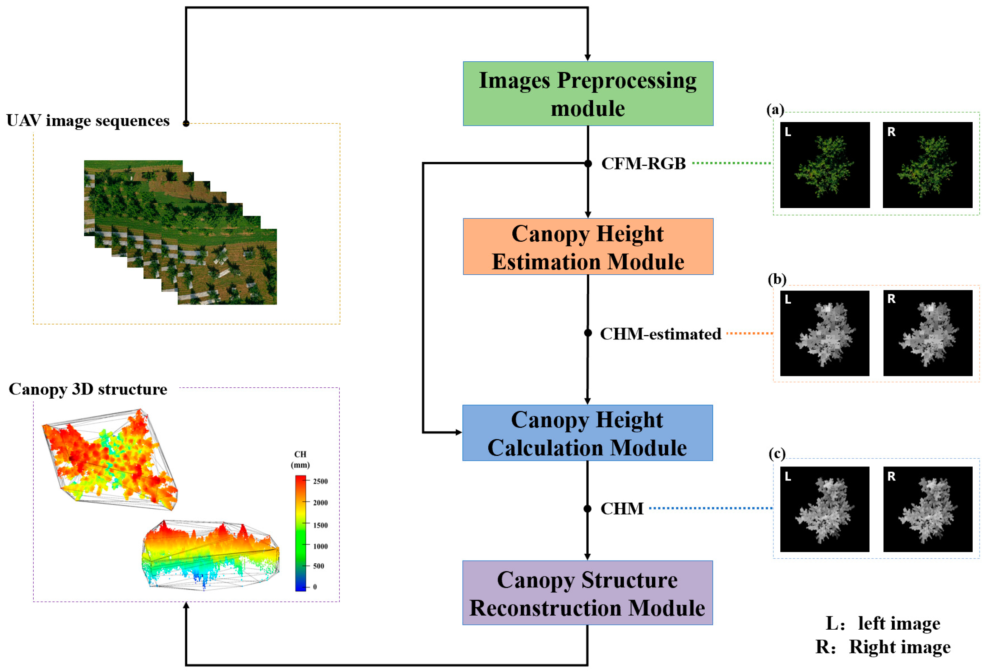
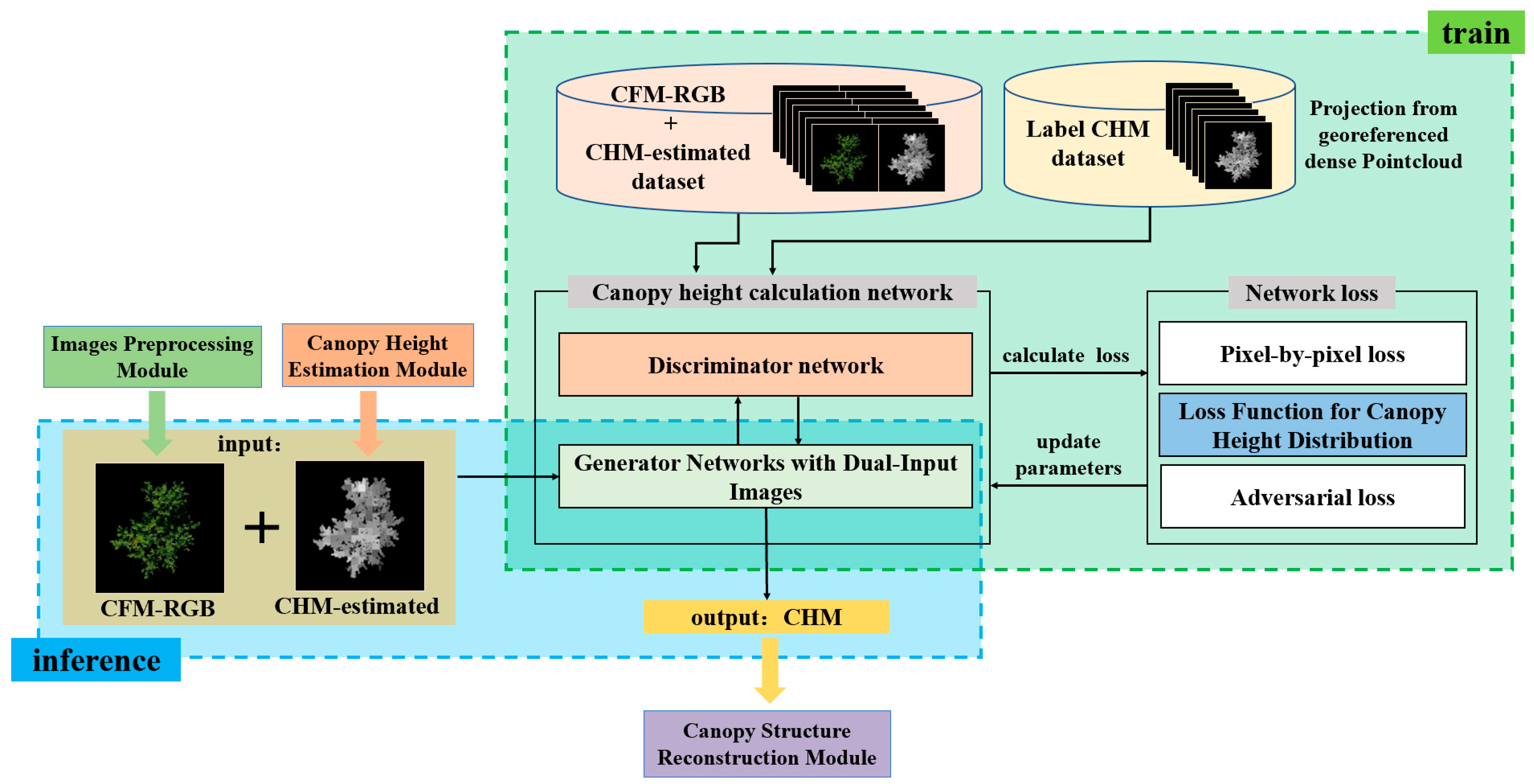
This section mainly describes the method used in this study. Figure 2 illustrates the functional structure of the method, which consists of the following components.
(1) Image-Preprocessing Module: In order to minimize the impact of ground background information on the estimation of canopy height, this module removes the background information in aerial images and generates a standard binocular canopy foreground RGB map (CFM-RGB) of the fruit tree target. This facilitates the subsequent process of canopy height estimation. The details of this process are described in Appendix A.1.1.
(2) Canopy Height Estimation Module. This module utilizes the canopy height estimation method proposed in this paper, which is based on block structural similarity. It performs matching of corresponding areas between binocular CFM-RGB maps using block similarity metrics and calculates the binocular parallax to obtain a canopy-height-estimated map (CHM-estimated) (corresponding to Section 2.2.1).
(3) Canopy Height Calculation Module based on the correlation between canopy color and height distribution: This module uses the canopy height calculation network proposed to calculate the Canopy Height Map (CHM). It takes CHM-estimated and CFM-RGB as inputs and uses the canopy foreground RGB information to guide the calculation of CHM. The module then outputs the refined CHM (Corresponding to Section 2.2.2).
(4) Canopy structure reconstruction module: In the task of simulating long baseline binocular canopy structure measurements using a single UAV lens, the 3D structure of the canopy is obtained from the refined binocular CHM via the canopy structure reconstruction module. This module is described in detail in Appendix A.1.2.
This paper focuses on the canopy height estimation module and the canopy height calculation module within the overall structure of this methodology.

2.2.1. Canopy Height Estimation Module

Since there is a strong correlation between the calculability of canopy height and the image quality of the input canopy height estimation module proposed in Section 2.2.2, the performance of the model proposed in this paper can be further enhanced if the speed and accuracy of canopy height estimation can be improved in the CHM estimation process. However, conventional binocular depth estimation algorithms typically rely on pixel-point matching [23,24]. These algorithms often require generating a larger number of feature points for the subsequent matching process, resulting in reduced efficiency in estimating canopy height. Additionally, these algorithms are highly sensitive to variations in texture and lighting conditions, leading to an increased number of false matches in the foreground of complex fruit tree canopies. Consequently, this negatively impacts the accuracy of canopy height estimation.
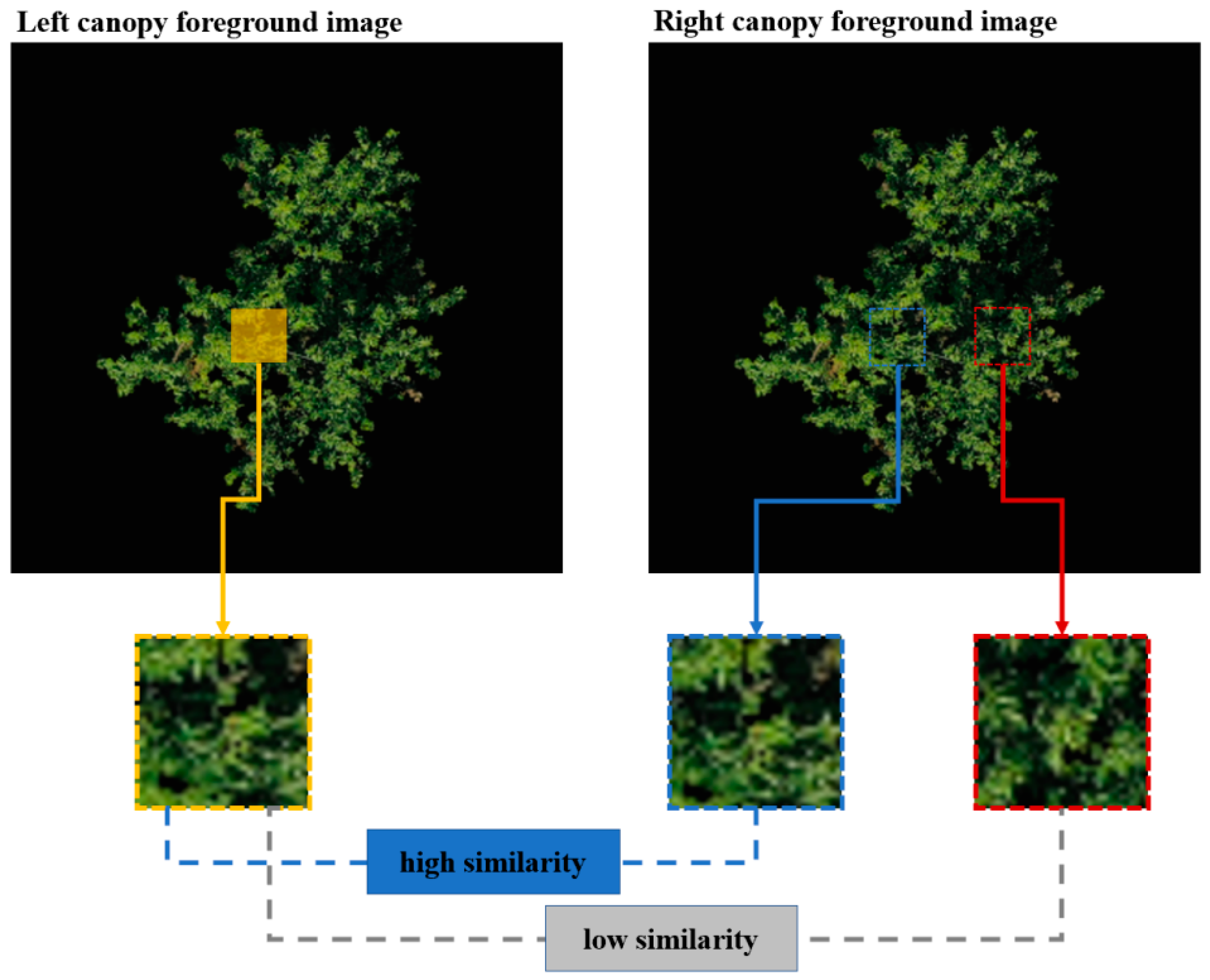
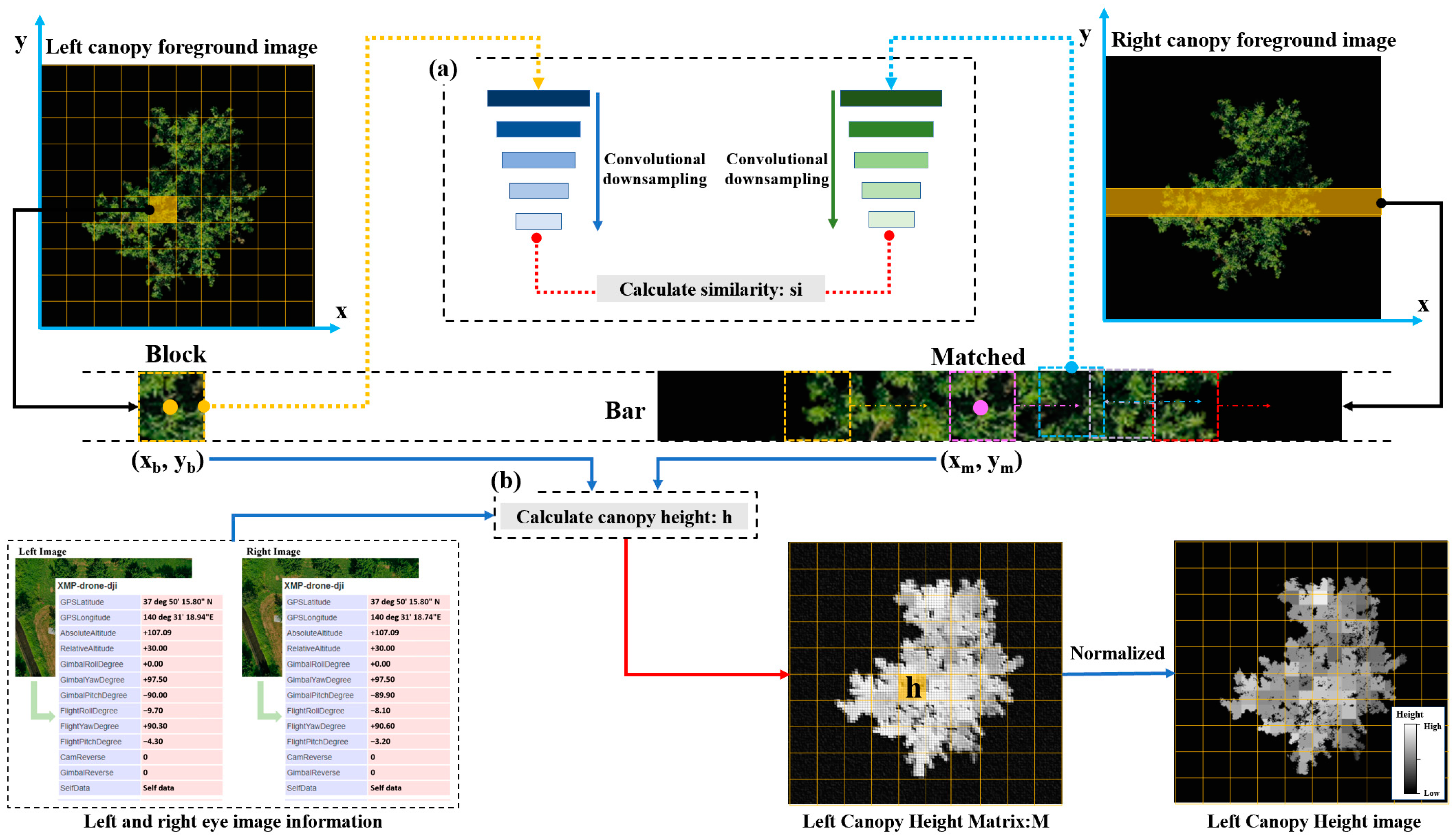
In this paper, we observe that in binocular photographic images with long baselines, the same region in the canopy shows high structural similarity between the binocular images (as depicted in Figure 3). However, the canopy texture details of fruit trees are more intricate. Based on this experimental phenomenon, we hypothesize that we can use the high-dimensional information similarity between canopy structures as a metric for binocular matching. Therefore, based on this concept, the canopy height estimation module of this paper provides a method for estimating canopy height based on the structural similarity of blocks. The core idea is to extract high-dimensional architecture traits from the binocular canopy blocks using a down-sampling strategy. This allows for the comparison of structural similarity. The specifics of this approach are as follows:
In the process of canopy block matching, the accuracy of the similarity between blocks directly affects the calculation of subsequent block height values. This method is designed to optimize the utilization of the structural characteristics of canopy blocks in order to determine the similarity between two blocks. To achieve this, the two block images are initially down-sampled before the similarity of the blocks is computed [this process is illustrated in Figure 4a and Algorithm 1 outlined in the pseudo-code]. Subsequently, the high-dimensional features of the two blocks are extracted, and their similarity is calculated based on the high-dimensional feature maps. This approach enhances the significance of the canopy’s structural features in determining the structural similarity of the blocks while reducing the impact of canopy details on the structural similarity. Then, the distance between the high-dimensional feature maps of the two blocks is calculated. (In this paper, the cosine distance was chosen as the measure of similarity.) The smaller the cosine distance between the two high-dimensional feature maps, the higher the similarity in terms of canopy structure between them. The formula for determining the cosine distance is shown in Equation (1):
d c o s M L , M R = 1 i = 1 m j = 1 n M L i , j M R i , j i = 1 m j = 1 n M L i , j 2 i = 1 m j = 1 n M R i , j 2
where ML and MR are the high-dimensional feature maps of the left and right visual canopy blocks whose similarity is to be calculated by Algorithm 1, and their pixel matrices are MLm×n and MRm×n, respectively.
Algorithm 1. Similarity calculation process for binocular canopy block matching
Input: left eye block: BL, matched right eye block: BR
Output: similarity between canopy blocks: si
1: for i ← 1 to 5 do
2:  BLconvolutional_downsampling (BL, kernel size: 3×, step size: 1)
3:  BRconvolutional_downsampling (BR, kernel size: 3×3, step size: 1)
4: end for
5: ML, MR ← high-dimensional feature map of BL, BR, respectively.
6: si = dcos(ML, MR), the cosine distance between ML and MR by Equation (1)
Using the coronal block structure similarity measure mentioned above, divide the coronal foreground region into blocks (referred to as blocks in this paper). Then, in the other binocular image, find the most similar block by using each block of the coronal structure as a matching block (referred to as a matched block in this paper). Compute the centroid of the two matching blocks [as indicated by the coordinates (xb, yb) and (xm, ym) shown in Figure 4] in the parallax between binoculars. Because the UAV used in this study is integrated with an RTK module, assume that the flight altitude will not change drastically during the acquisition of the left and right views (as shown in Figure 4, for example). Then, based on the information from the photographic images, use the stereo vision principle to calculate the height value at the block [as demonstrated in Figure 4b]. Because of the typical binocular form correction that the preceding binocular canopy foreground-generating module already executed, only the region containing the upper and lower borders of the block area (as depicted in the bar area in Figure 4) can be used to search for the matching block.
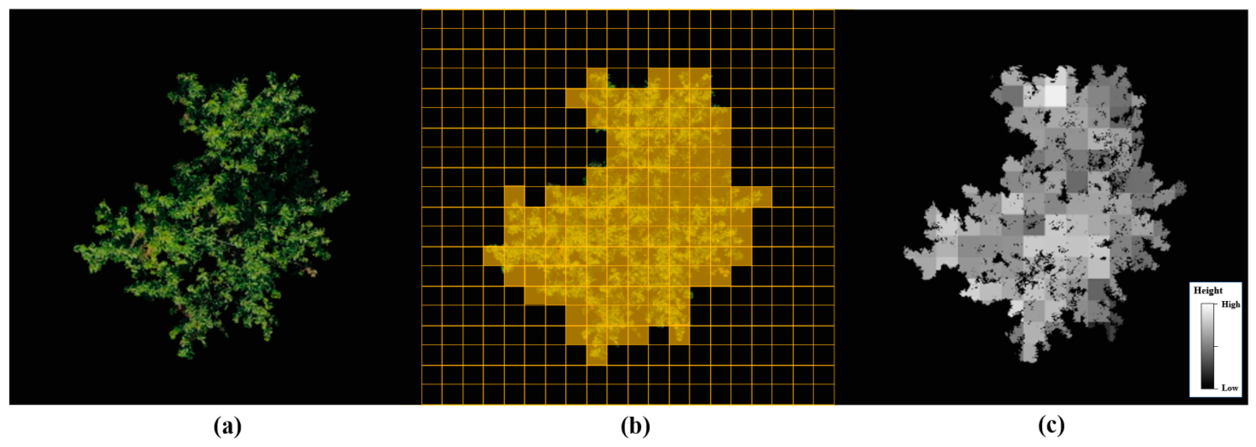
In order to obtain the left-eye canopy foreground height matrix M, traverse all of the left-eye CFM-RGB blocks, use the above matching method to identify the best matching region, and calculate the height value. Next, eliminate any outliers from M, and note the maximum value, or hmax, in M. Finally, normalize the matrix M to a grayscale image with 0–255 levels, keeping only the canopy foreground region in the grayscale image [illustrated in Figure 5c]. To generate the right-eye CHM-estimated map, swap the left- and right-eye CFM-RGB maps and apply the previously described canopy height estimation method based on block structure similarity. Figure 5 displays the CFM-RGB map, the canopy foreground block division image, and the CHM-estimated map. According to the CHM-estimated map, the total height of the canopy in the area is represented by the height value of each block in the picture. In addition to serving as the input object for the following module that calculates canopy height, the CHM-estimated map also provides canopy height value guidance for the network process used to calculate canopy height in the foreground. This allows the network to incorporate RGB information from the foreground to calculate the heights of the canopy at each location more precisely. In addition, the gray values in the CHM-estimated map are records of the relative heights of each canopy segment. These records serve as the vertical mapping scale for the subsequent reconstruction of the canopy, ensuring that the new canopy has a reasonable 3D scale.

2.2.2. Canopy Height Calculation Module

Fruit tree canopy height calculation requires not only the generation of a reasonable canopy height distribution but also the certainty of the invariance of the contour shape of the canopy foreground since the 3D structure of the canopy needs to be reconstructed from the computed fine CHM. In light of this, this paper suggests a network for calculating the foreground height of fruit trees using the correlation between canopy color and height distribution. Figure 6 displays the training flowchart for this network model. The network uses a generative adversarial network structure. Here, the “generator network with dual input images” is utilized to calculate canopy height. The generator takes two inputs, CFM-RGB and CHM-estimated, which supply the RGB color information of the canopy foreground and the in-region predicted height values of the canopy, respectively. The generator network combines the canopy foreground color from CFM-RGB and the canopy height estimation information from CHM-estimated, from which it learns the deep mapping relationship between the canopy RGB information and the estimated height information for the real canopy height, generates a refined CHM image with reasonable canopy height distribution characteristics (introduced in the Generator Network with Dual Input Images Section), and outputs a refined CHM with the canopy heights. The loss function of canopy height distribution proposed in this paper (introduced in the Loss Function for Canopy Height Distribution Section) is used in the calculation process to accelerate the convergence speed of the generator network and enhance the reasonableness of the height distribution of the generated CHM; meanwhile, the pixel-by-pixel loss function is used to ensure the invariance of the two-dimensional contour structure of the computed CHM. In addition, the ‘discriminator network’ learns how to distinguish between the generated CHM and the label CHM and improves the ability of the ‘generator network’ by using dual input images to calculate the canopy height during the adversarial training of the generator and discriminator. Such a network structure meets the needs of fruit tree canopy height calculation. To train the canopy height calculation network, the label CHM was generated by projecting terrestrial-laser-scanner-acquired point cloud data.

Generator Network with Dual Input Images

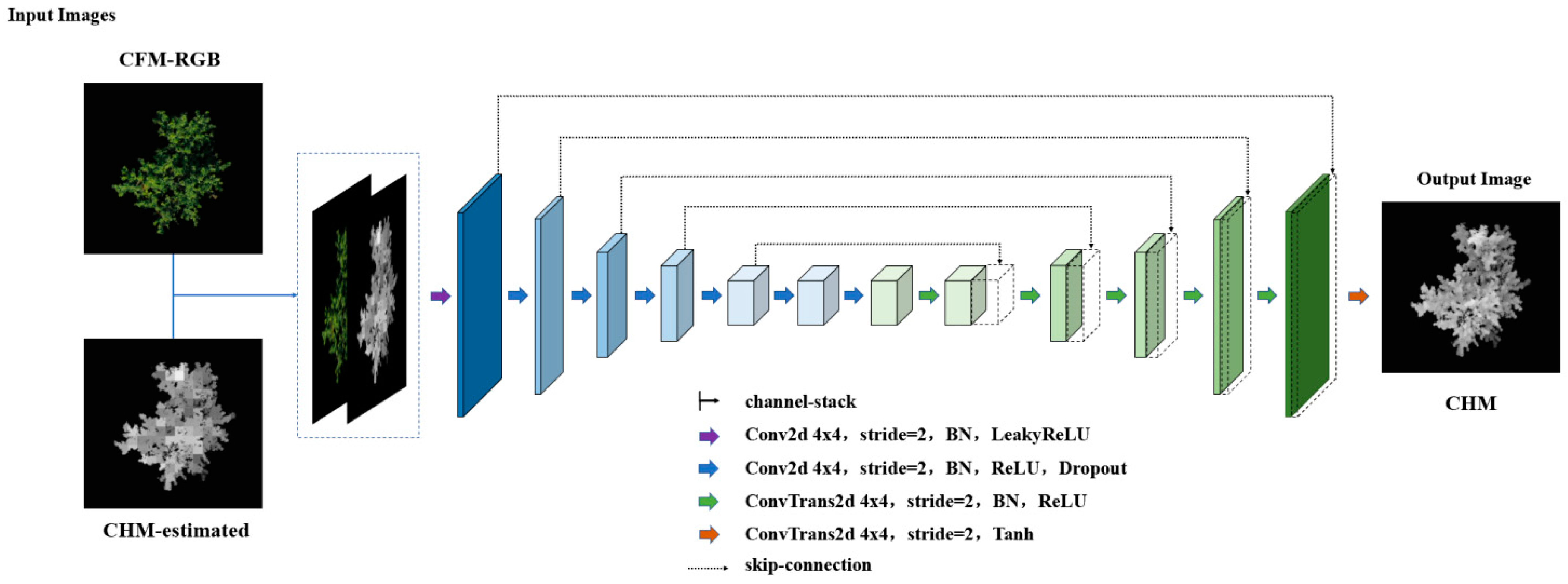
The network’s specific structure is shown in Figure 7. The generator is based on U-Net, with CFM-RGB and CHM-estimated as dual inputs and the computed fine CHM as the output, the last of which is designed to utilize the canopy foreground RGB information in CFM-RGB and the predicted canopy height information in CHM-estimated to guide the generator network towards learning the label CHM’s canopy height distribution characteristics to generate a fine and reasonably distributed CHM.
In the U-Net down-sampling process (Figure 7), a continuous convolutional layer module is used to extract the input CFM-RGB and CHM-estimated features at the same time and fuse the RGB information of the canopy layer and the height information of the canopy layer during the down-sampling process to obtain the high-dimensional features that are enriched with the color and height information of the canopy layer; the inverse convolution module is used to reconstruct the image step-by-step in the up-sampling process, and the skip-connection structure is used in this process to jump-connect the down sampling feature layers of the same scale, rendering the image restoration process capable of fusing the feature information of the canopy layer’s color tone and outline at different scales, in addition to enhancing the quality of the reconstruction of the image.

Loss Function for Canopy Height Distribution

The generator uses a pixel-by-pixel L 1 loss function to ensure the invariance of the 2D contour structure of the generated CHM, but in the actual training process, only using this loss will render the network incapable of learning the characteristics of canopy height distribution, which will lead to problems such as slow convergence of the generator network, unreasonable generation of canopy height distribution, and other problems. Therefore, this paper proposes, for the first time, the canopy height distribution loss function lossQD (quantity and distribution loss of canopy height), which evaluates the similarity of the distribution of height values between the generated CHM and the label CHM and makes the distribution of canopy heights generated by the generator network more reasonable. This loss consists of canopy height value quantity distribution loss, i.e., lossquality, and canopy height value location distribution loss, that is, lossdistribution, and it is defined as shown in Equation (2):
l o s s Q D = l o s s q u a n t i t y + l o s s d i s t r i b u t i o n
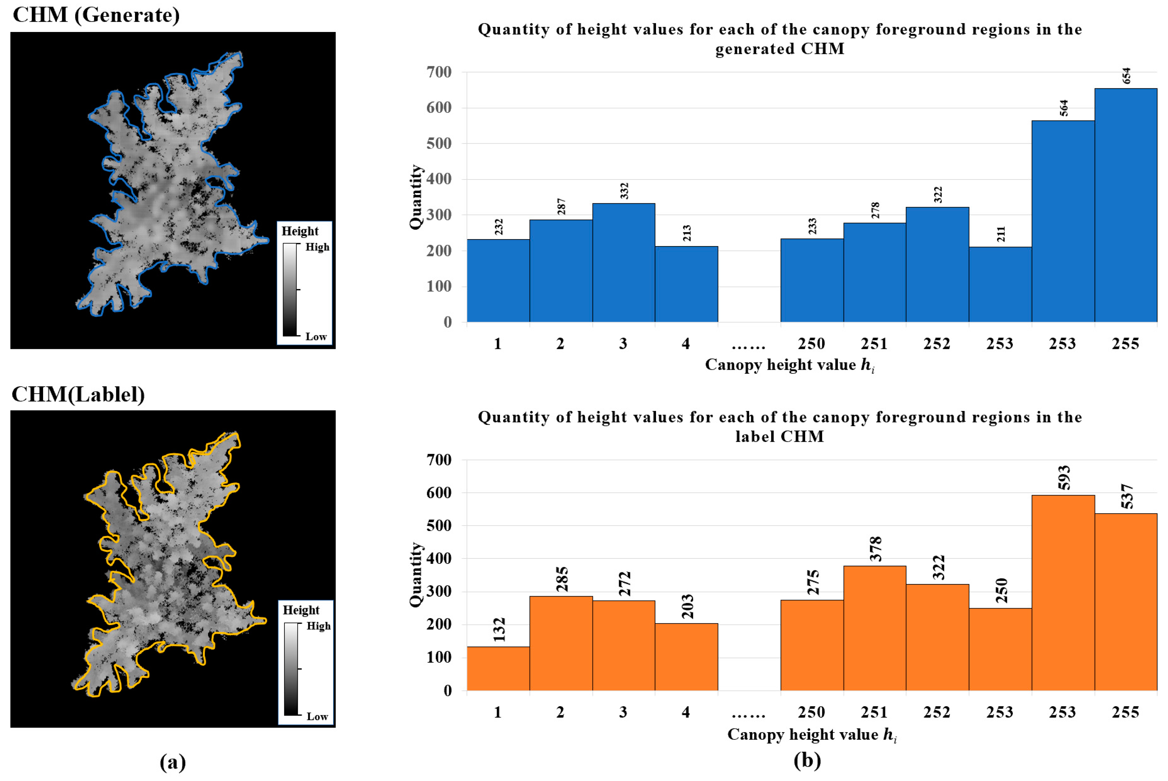
where lossquality is calculated by counting the number of height values in the canopy region, focusing on the part of the generated CHM and the label CHM in the foreground region of the canopy only [shown in Figure 8a], and counting the number of height values of the canopy in the region [as shown in Figure 8b, the height value of the canopy is represented by the grayscale values between the 0–255 threshold]. This is defined in Equation (3):
l o s s q u a n t i t y = i = 1 255 g i t i 255
where g(i) is the number of pixels generating the ith level of height values in the foreground portion of the CHM, and t(i) is the number of pixels generating the ith level of height values in the foreground portion of the true CHM, and the difference between the two is used as a loss function so that the network learns the variability between the distributions of the number of height values in the canopy.
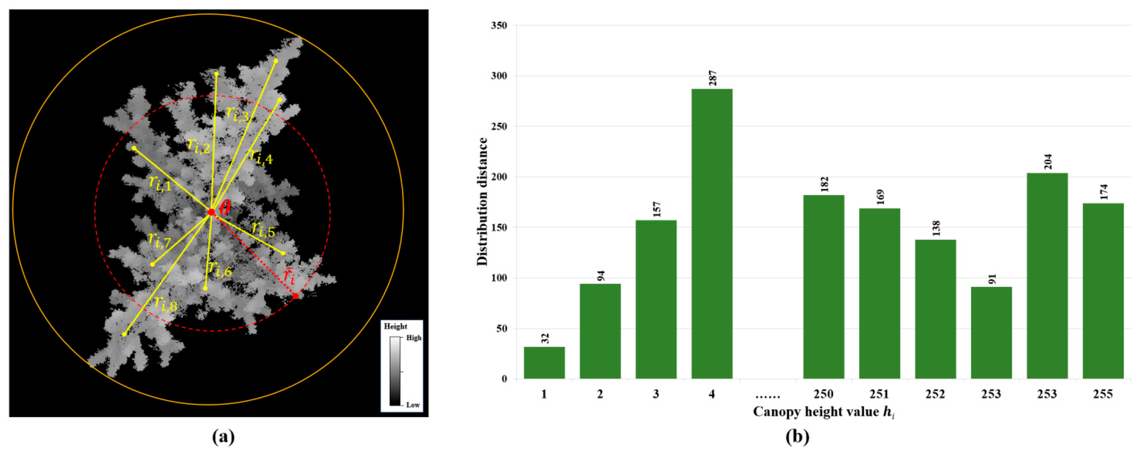
lossdistribution is calculated by determining the distribution distance of each height value in the canopy region from the center of the canopy, first determining the center O of the smallest outer circle in the canopy foreground [Figure 9a]. First, the center O of the smallest outer circle in the foreground of the canopy is determined. Then, the distance r i , 1 , r i , 2 , r i , 3 r i , j r i , m 1 , r i , m between a height value h i ( i [ 1 , 255 ] ) and the center O of the circle in the canopy (where m is the number of height values h i in the canopy) is determined. In this paper, we define the distribution distance of the canopy height value hi as r ¯ i , with r ¯ i denoting the distance from the main distribution location of this height value in the canopy to the center point of the canopy [as shown by the radius of the red dashed circle in Figure 9a], which is defined as shown in Equation (4):
r ¯ i = j = 1 m r i , j m , j 1 , m
The calculated CHM and the distribution distance r ¯ i for each height value h i are shown in Figure 9b.
In order to describe the variability between the two images in terms of the distribution distance of canopy height values, this paper defines l o s s d i s t r i b u t i o n as shown in Equation (5):
l o s s d i s t r i b u t i o n = i = 1 255 | g ( r ¯ i ) t ( r ¯ i ) | 255 , i 1 , m
where g( r ¯ i ) is the distribution distance of a level of height values in the foreground part of the generated CHM, and t ( r ¯ i ) is the distribution distance of a level of height values in the foreground part of the label CHM. Using the difference between the two as a loss function allows the network to learn about the variability between the distributions of the locations of the canopy height values.
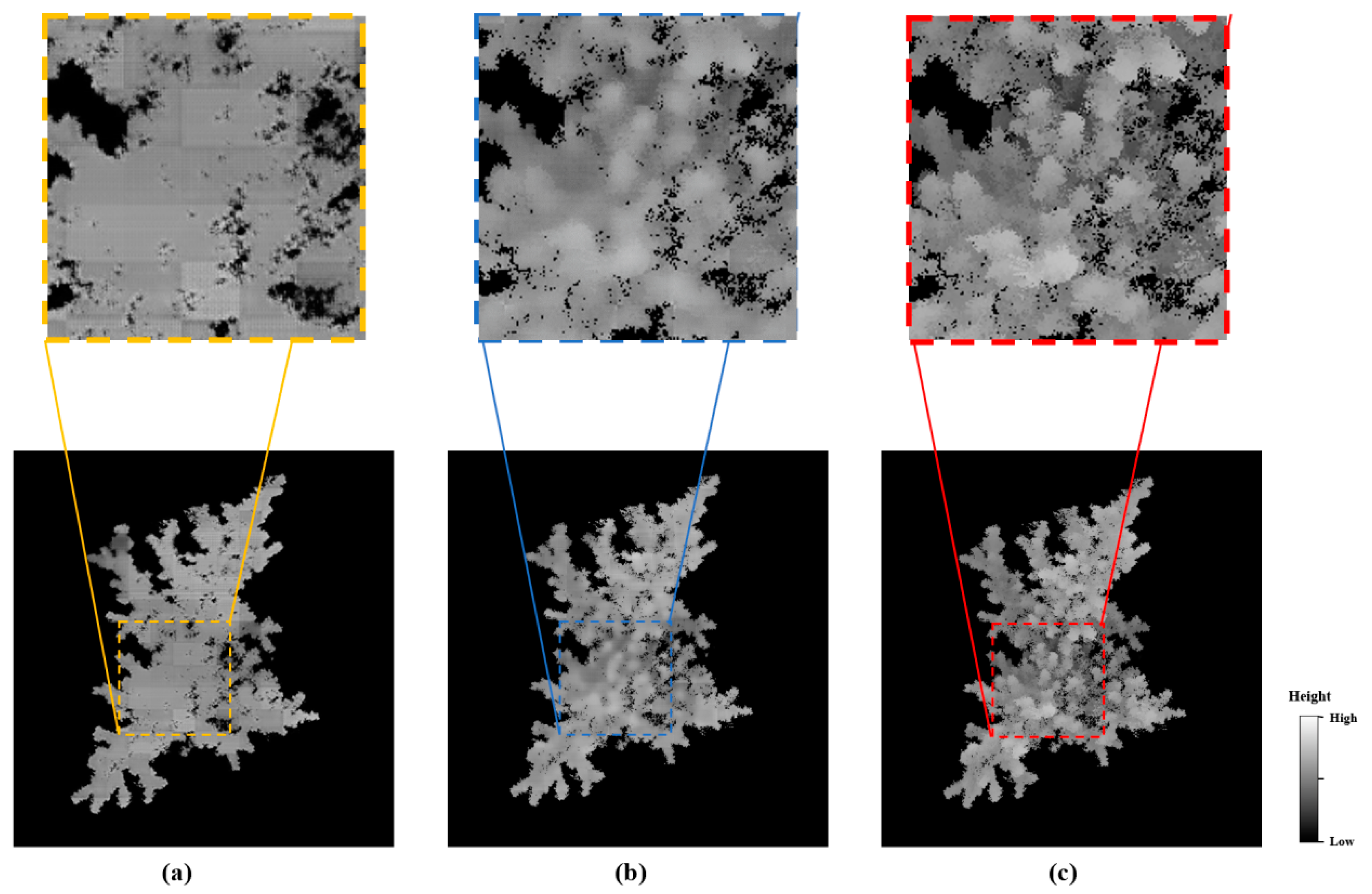
Before the fusion of lossquality and lossdistribution, we first normalized them to [0, 1] via decimal scaling to ensure that both of their losses are of the same scale. Figure 10 shows the comparison effect before and after adding lossQD to the generator’s loss function for the same number of training rounds. In contrast to Figure 10a, Figure 10b illustrates a distinct variation in height within the inner canopy, and in terms of canopy details, this result is more in line with the actual CHM. As can be observed, the network can significantly increase the quality of CHM generation and speed up the training process after the addition of lossQD within the same training iteration rounds. The generator significantly increases CHM generation quality and quickens the network’s convergence process after lossQD is added.

2.3. Canopy Architecture Traits Extraction

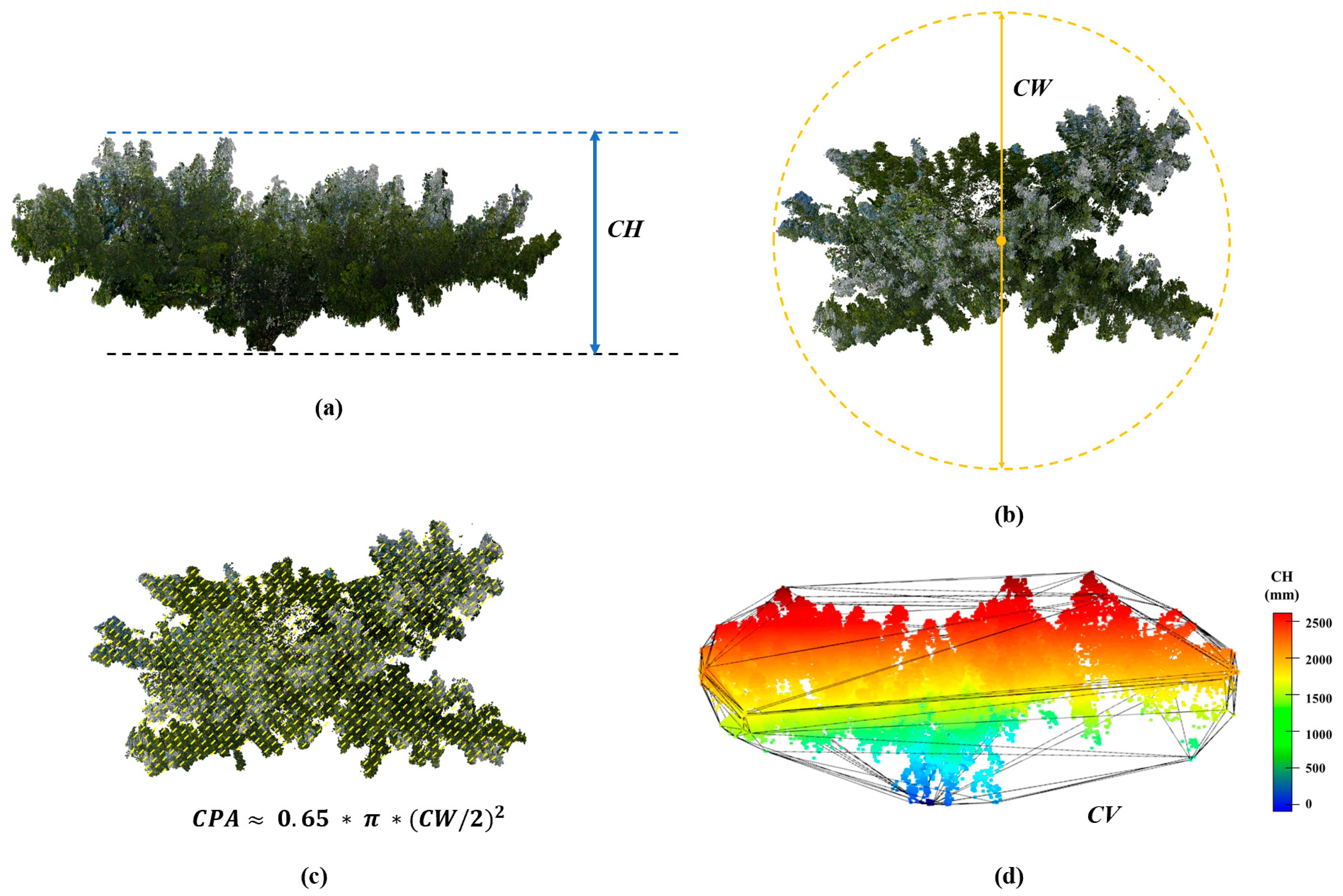
The measurement of fruit tree canopy architecture traits is mainly concerned with the relevant parameters of a fruit tree canopy in 3D space, of which the most important structural parameters include tree height, canopy width, canopy projected area, canopy volume, etc. [25,26,27,28]. These architectural traits directly reflect the growth status of fruit trees and play an important guiding role in the monitoring and management of fruit trees. Therefore, in this paper, the above four canopy structure parameters are used to evaluate the performance of canopy measurement methods, and the definitions of these four canopy structure parameters are as follows:
  • CH (Canopy Height)—the vertical distance from the highest part of the canopy to the ground, as shown in Figure 11a;
  • CW (Canopy Width)—the diameter of the smallest outer circle of the vertical projection of the canopy, as shown in Figure 11b;
  • CPA (Canopy Projected Area)—the vertically projected area of the canopy (empirical value used in this paper: C P A 0.65 π ( C W / 2 ) 2 [15], as shown in Figure 11c;
  • CV (Canopy Volume)—the volume of the 3D convex envelope of the canopy, as shown in Figure 11d.

2.4. Implementation

In the experiment, we employed the same computer, with 32 GB of RAM and an Intel i7-12700F CPU (Intel, Santa Clara, CA, USA) running at 2.10 GHz, to execute all the methods. Additionally, this machine has an RTX4090 GPU (Nvidia, Santa Clara, CA, USA) with 24 GB of VRAM. The operating system used for the experiment is Ubuntu 18.04. The proposed approach was implemented using Python 3.7. The canopy height calculation network and foreground segmentation network for this method were implemented using the Pytorch version 1.12.1 framework. Appropriate adjustments were made to the training process’s epoch (epoch = 500), learning_rate (learning_rate = 0.001), and batch_size (batch_size = 4). With a calculation amount amounting to 28.2 GFLOPS and 5.45 M parameters, the training procedure took roughly 6 h, the more details can found in Supplementary Materials. The SFM+MVS method was executed using Pix4D Mapper version 1.1.38 software. Demo software version 1.0 and data can be accessed at https://github.com/I3-Laboratory/EasyCanopy (accessed on 22 February 2024).

3. Results

Currently, the method based on SFM+MVS reconstruction is the most commonly used method in the field of UAV agricultural surveying and mapping [29,30,31,32]. In this method, first, feature points between image sequences are extracted; then, feature matching is performed, and the spatial position relationships between photographic images are estimated; finally, a three-dimensional point cloud of the object based on the estimated camera parameters is constructed. The existing fruit tree canopy architecture trait measurement methods are mostly based on this method. Therefore, we chose SFM+MVS as a comparison method. Since UAV photogrammetry often requires using oblique photography technology to improve canopy structure reconstruction, the camera angle and the UAV route need to be adjusted to ensure the overlap rate between the image sequences, which undoubtedly increases the cost of image data acquisition. In order to further simplify the UAV aerial photography work and reduce the cost of data acquisition, the UAV aerial photographs were taken using a vertical overhead angle in this experiment. This section details comparative experiments conducted in terms of canopy structure traits (introduced in Section 3.1), canopy 3D structure (introduced in Section 3.2), and canopy reconstruction efficiency (introduced in Section 3.2).

3.1. Validation via Canopy Structure Traits

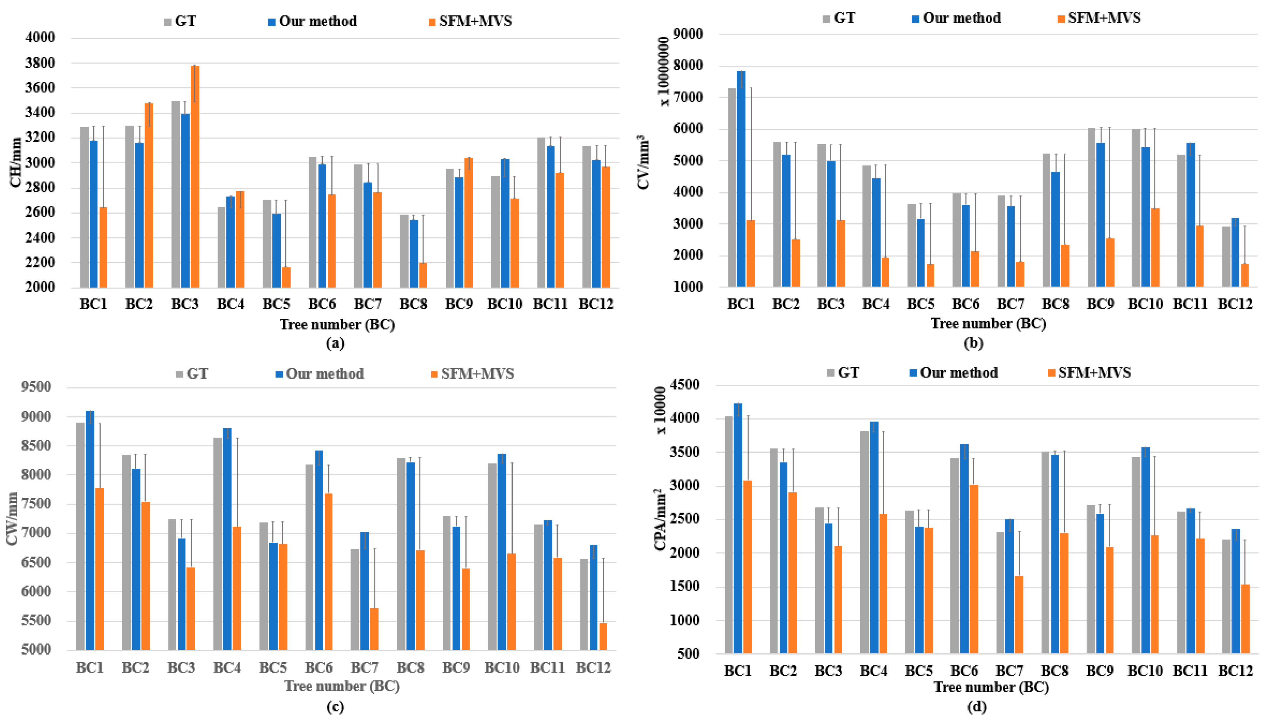
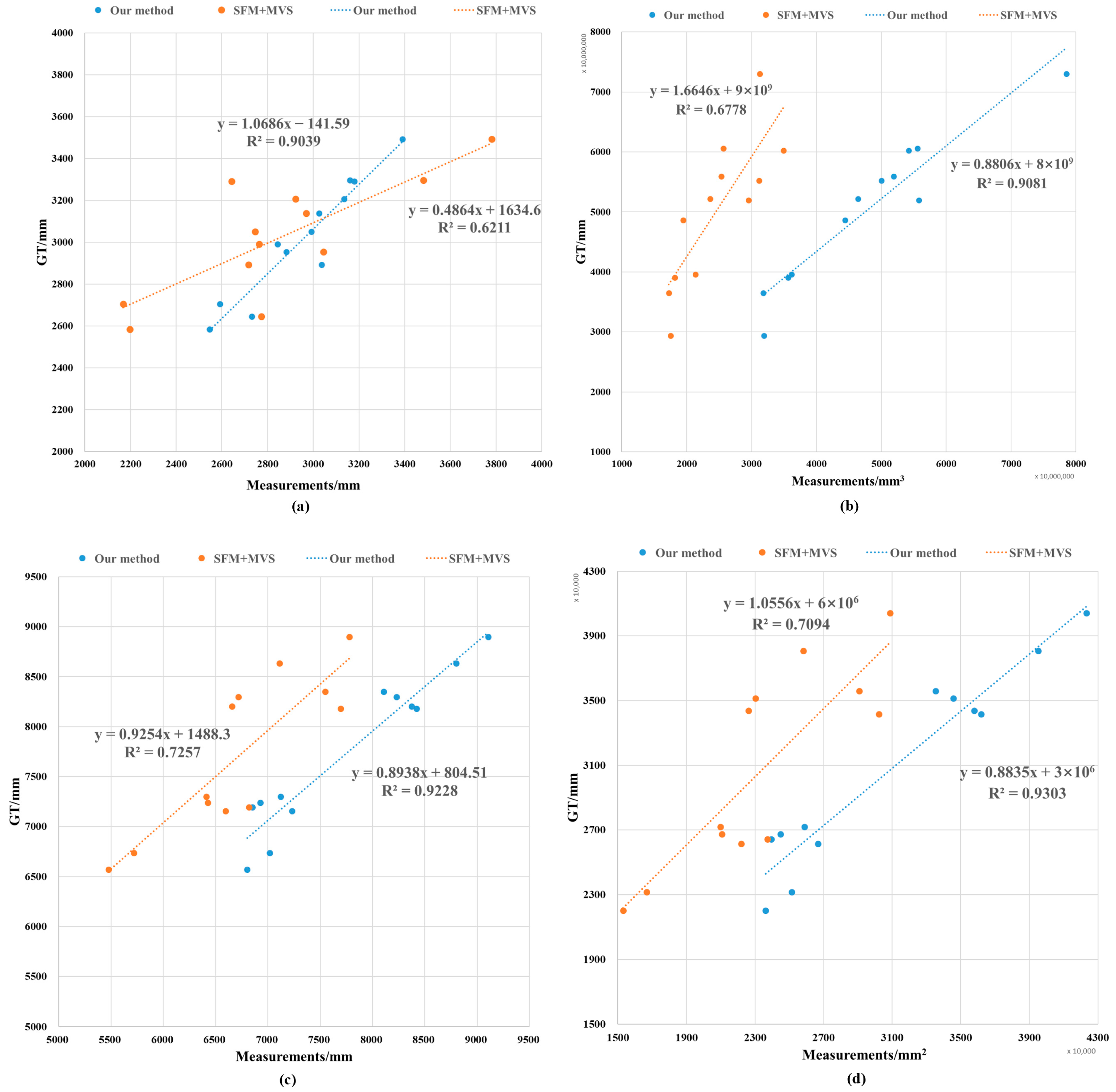
In this section, we calculate the error rate and linear correlation between the measurement results and the true values. Figure 12 shows the results of a comparison between the canopy structure parameters measured using the two methods and the true values for each fruit tree. Table A1 shows the absolute values of the errors between the canopy structure parameters measured using the two methods and the true values of each fruit tree. Figure 13 shows the linear correlation between the canopy structure parameters measured using the two methods and the true values for each fruit tree. Figure 14 shows the structural visualization point cloud reconstructed using the two methods and its terrestrial-laser-scanning point cloud for each fruit tree canopy.
As shown in Figure 12 and Table A1, the experimental error rate of the proposed method for each fruit tree canopy characteristic parameter is small, with an average error rate of 3.296% for the CH, 9.067% for the CV, 2.772% for the CW, and 5.541% for the CPA, and proposed method has a small error rate for each canopy structural parameter. The average error rate absolute value between the measurement results and the true value for each canopy structure parameter assessed using this method is below 10%. On the other hand, the SFM+MVS method has a higher error rate for each canopy structure parameter, and the absolute value of the average error rate for the CV parameter is more than 50%. The measured values of the CV parameters determined using the SFM+MVS method are all smaller than the ground-truth values. It can be speculated that the three-dimensional structure of the canopy reconstructed using this method has a large loss, resulting in a large gap between the convex hull volume and the actual canopy volume.
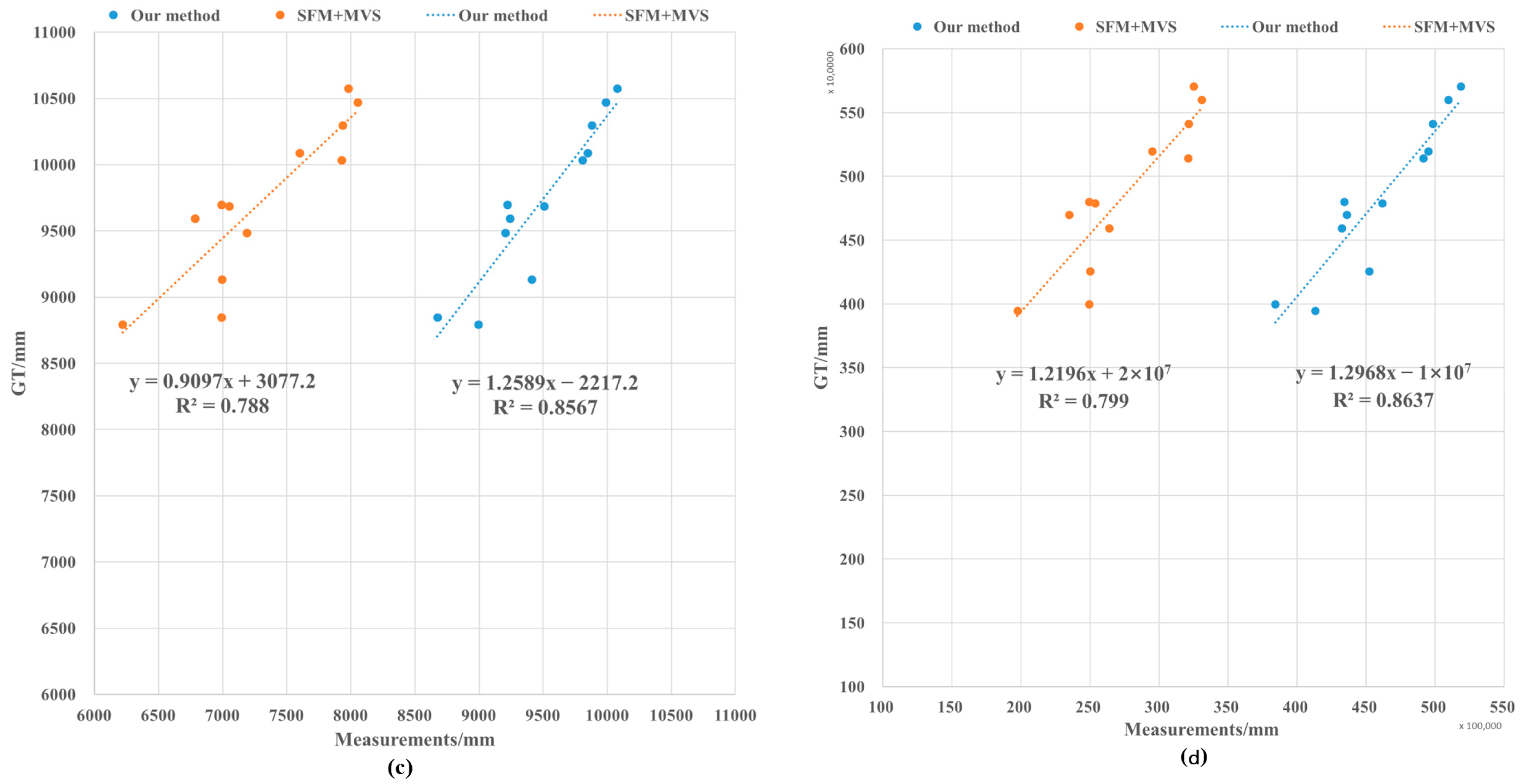
Meanwhile, as shown in Figure 13, the correlation coefficient R 2 (which measures the linear correlation between the measured value and the true value) of the proposed method for the CH is 0.9039, on the CV is 0.9081, on the CW is 0.9228, and on the CPA is 0.9303. The linear correlation coefficients R 2 of the structural parameters of the reconstructed canopy for the proposed method and the true value are all in the range of 0.9303. The linear correlation coefficients between the structural parameters of the reconstructed canopy and the true values for this method are all above 0.9, which shows a strong linear correlation between the measured values and the true values, while the linear correlation coefficients between the structural parameters of the reconstructed canopy and the true values of the indicators for the SFM+MVS method are below 0.8, which is a weaker linear correlation compared with that of the proposed method. For the CV parameters, the r2 of the SFM+MVS method is only 0.6778, which also shows that there is a large error in the measurement results of this method.

3.2. Validation

As shown in Figure 14, by comparing the reconstructed fruit tree canopy structure with that of SFM+MVS, although the reconstructed fruit tree canopy point cloud structure in this paper is different from that of the terrestrial laser scanner point cloud in relation to some details (as shown in the blue dashed area in Figure 14b), the reconstructed fruit tree canopy structure has greater similarity with the 3D structure of the ground point cloud in terms of the overall convex packet morphology. This verifies the accuracy of the measurement of the fruit trees in terms of their canopy structure parameters. On the other hand, the point cloud reconstructed using the SFM+MVS method is centered on the top of the fruit tree canopy, which is mostly in the form of a slice. The reconstructed canopy structure is partially missing from the top-view perspective (as shown by the orange dashed area in Figure 14c). The bumpy packet structure is also quite different from that in the terrestrial-laser-scanner-scanned canopy point cloud, which did not reconstruct the 3D structure of the canopy well, and this directly affects the accuracy of the parameters relating to the canopy structure of fruit trees. This also directly affects the accuracy of the canopy structure parameters. It can be seen that the method proposed in this paper can better reconstruct the 3D structure of a fruit tree canopy and obtain more-accurate canopy structure parameters using UAV aerial images compared with the SFM+MVS method.

3.3. Reconstruction Efficiency Comparison

In addition, as shown in Table 1, in terms of the reconstruction cost for the fruit tree canopy, the proposed method requires only two images to complete the reconstruction of a single fruit tree canopy. It takes only 24 images to complete the reconstruction of the canopies of all 12 fruit trees, with an average of 30 s required for the reconstruction of a single fruit tree canopy. In contrast, the SFM+MVS method used 203 images and took 02 h:06 m:04 s to complete the reconstruction of all 12 fruit trees. The proposed method reduces the time cost of canopy reconstruction by 95.2% and the cost of images needed for canopy reconstruction by 88.2%. It can be seen that the proposed method can reduce the image acquisition cost of fruit tree canopy reconstruction and the time required for fruit tree canopy structure reconstruction more substantially.
Although the Pix4D software based on the SFM+MVS method utilizes the GPS positioning information of UAV aerial photography images to assist in the reconstruction of fruit tree canopies, it still needs to satisfy the geometrical constraints of the camera viewpoint based on the feature point matching of the images, so this method’s feature-point-matching process with respect to images is inevitably affected by the ground background and the surrounding fruit tree canopy. This affects the derivation of camera position in the SFM process. At the same time, because the UAV aerial images were acquired using tilt photography, the MVS process of this method is not sufficient for employment in the dense reconstruction of the viewing angle information, resulting in the dense reconstruction of the canopy 3D structure being inaccurate, a trait specifically reflected in the fact that the reconstruction of the canopy point cloud has different degrees of missing features, which seriously affects the accuracy of the canopy structural parameters. It can be seen that the image sequences of UAV aerial photography obtained based on the SFM+MVS method could not yield a very good reconstruction of the 3D structure of the canopy, so, temporarily, UAV aerial photography and the SFM+MVS method cannot be used to obtain more accurate measurements of the canopy architecture traits of a single fruit tree. The proposed method uses the canopy height calculation network to learn the distribution characteristics of canopy height and obtain a fine canopy height image. On this basis, a more accurate 3D canopy structure can be obtained.
In addition, as shown in Table 1, regarding the cost required for fruit tree canopy reconstruction, the SFM+MVS method requires a large number of photographic images and a great deal of time for canopy reconstruction. On the other hand, since this method cannot distinguish the front background of a canopy in the canopy reconstruction process, the redundant ground background information is involved in the camera position inference of SFM and the multi-view dense reconstruction process of MVS, resulting in additional computational overhead and an increase the computational time required for canopy reconstruction when using this method. In this paper, the proposed method requires only two images for the reconstruction of the same fruit tree canopy target. The foreground generation of the same fruit tree canopy target in binocular vision is performed before canopy height prediction, avoiding the influence of the ground background and other fruit tree canopies on the reconstruction process. At the same time, the canopy height prediction method based on the similarity of the block structures proposed also further accelerates the speed of fruit tree canopy height prediction. It can be seen that compared with the SFM+MVS method, the proposed method has lower costs and a faster speed in canopy reconstruction.

4. Discussion

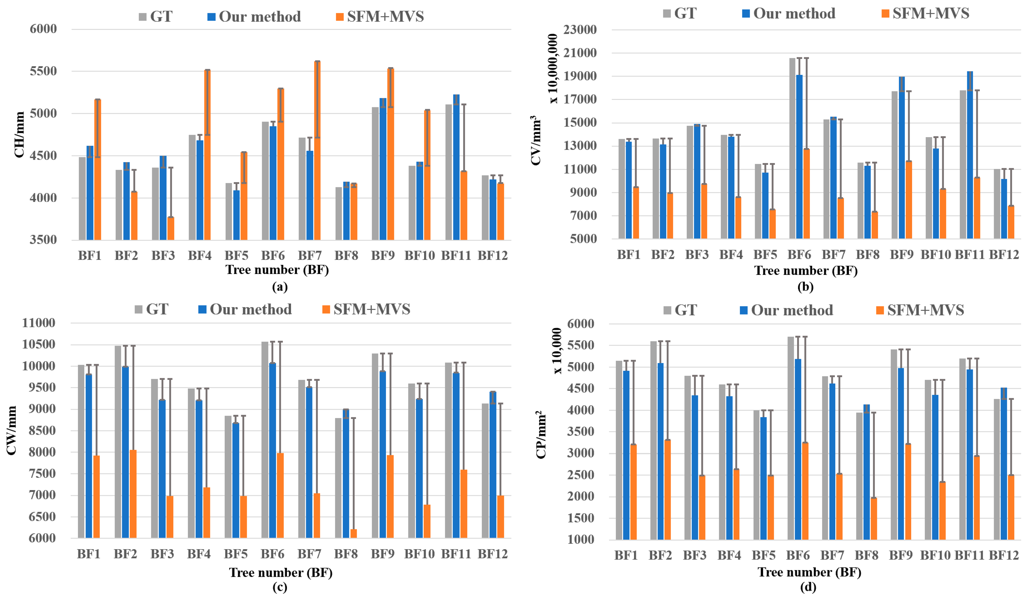
For precise fruit tree management, canopy architecture traits are important, and with the rapid development of UAV sensing techniques, phenotyping such traits can be performed efficiently. However, there are still limitations of the current solutions, including the hardware costs of Lidar-sensor-based solutions and the calculation costs of RGB photogrammetry-based solutions. In this paper, we propose a novel UAV-based single-lens stereoscopic photography method designed to mitigate these challenges. The methods were evaluated with respect to a peach orchard in the summer, and the results demonstrate efficiency and cost-effectiveness in canopy reconstruction, significantly reducing both the time and computational demands traditionally associated with such tasks. We also recognize that canopy architecture traits are needed in the winter as well, so, in addition, a preliminary experiment was also conducted using the image data of winter orchard trees collected in another experiment field in Okayama prefecture (the experimental objects included 12 peach trees, BF1-BF12), as shown in the Appendix. The proposed method was also compared with the SFM+MVS method. The experimental results show that the proposed method also shows effectiveness in the measurement of the canopy structures of fruit tree branches in the winter (the experimental results are shown in Appendix A.3, Figure A3, Figure A4, Figure A5 and Figure A6, and Table A2 and Table A3).
Although the proposed method will produce more-accurate fruit tree canopy architecture trait measurement results in experiments, it is undeniable that measuring such traits based on a single UAV lens is still a challenging task. First of all, in the experimental results, it can be found that there are still some differences between the reconstructed canopy and the real canopy in terms of the structural details of the proposed method, especially in relation to the winter fruit tree branches and the trunks of the object. The proposed method also failed to capture more branches and trunks, resulting in errors in the CW and CPA parameters of the fruit trees. This misrepresentation was caused by the inaccurate segmentation of the foreground (canopy), making the CFM-RGB partially misrepresented, which affects the subsequent 3D structure reconstruction of the canopy. It can be seen that the performance of the foreground segmentation network affects the accuracy of canopy reconstruction, and a better foreground segmentation network can be selected in the future to enhance canopy reconstruction. Secondly, the current experiment was only carried out on fruit trees in a certain period, and the actual state of the canopy of the fruit trees (the color of the canopy leaves, the degree of canopy leaf coverage, etc.) changes dynamically with the change of season and time, which may pose a challenge with respect to the generalization ability of the canopy height calculation network and the canopy foreground segmentation network. Aerial photography data of fruit trees captured throughout the whole year can be collected to improve the learning ability of the network with respect to the canopy information of fruit trees in each period. If one needs to measure fruit trees in a new orchard [33,34,35], the model generated in this study can be applied or finetuned, using new trees as a training dataset.
The proposed method can efficiently measure the phenotypic traits of fruit tree canopies in large-area orchards; has guiding significance for fruit tree yield prediction, fruit tree pruning, water and fertilizer application, pest and disease control, etc.; and promotes the development of precision agriculture. The proposed method can be adapted to the edge devices carried by UAVs to realize online real-time phenotyping tasks. In addition, other phenotypic traits such as canopy light interception rate and leaf area index can be further measured based on the reconstructed fruit tree canopy structure. Finally, so far, the proposed method has been applied to fruit trees in orchards, but in future work, this idea can be applied to the phenotypic measurement tasks of other crops, such as field crops, low shrubs, and other scenarios, to broaden the scope of application of the proposed method in agriculture.

5. Conclusions

In conclusion, in this study, we developed a high-precision, fast, and low-cost method of measuring the canopy architecture traits of single fruit trees based on a single UAV lens. This method can quickly obtain the 3D structure of a fruit tree canopy with higher accuracy and calculate 3D characteristic parameter information regarding canopy structure, on the basis of which we can reduce the cost of fruit tree canopy data collection and processing. And compared to conventional methods, our method yields better results and has higher efficiency. It can be adapted to the fruit tree canopy architecture trait measurement tasks in different seasons and is suitable for the high-throughput and accurate measurement of the canopy structure of a single fruit tree in a wide range of orchard scenarios to assist in the analysis of the growth states of fruit tree canopies.

Supplementary Materials

A video about the workflow of this study can be found at https://youtu.be/A-MN9hlXiQ4 (accessed on 22 February 2024).

Author Contributions

Conceptualization, W.Z., X.P. and W.G.; methodology and software, W.Z., X.P., T.B. and W.G.; validation, W.G., T.B. and H.W.; data investigation and curation, D.T.; writing—original draft preparation, W.Z. and X.P.; writing—review and editing, X.P., W.G., W.Z. and H.W.; visualization, T.B. and H.W.; supervision, W.Z. and W.G. All authors have read and agreed to the published version of the manuscript.

Funding

This study was partially supported by the National Natural Science Foundation of China (NSFC) Program Number 62276009 and the Japan Science and Technology Agency (JST) AIP Acceleration Research Number JPMJCR21U3.

Data Availability Statement

Demo software and demo data can be accessed at https://github.com/I3-Laboratory/EasyCanopy (accessed on 22 February 2024).

Acknowledgments

The authors thank Yuichiro Fujii from the Okayama Prefectural Technology Center for Agriculture, Forestry, and Fisheries for providing access to Okayama orchard and Futaba Inc. for providing Lidar scanning data of Fukushima orchard.

Conflicts of Interest

The authors declare no conflicts of interest.

Appendix A

Appendix A.1. Methodologies of Image-Preprocessing Module and Canopy Structure Reconstruction Module

Appendix A.1.1. Image-Preprocessing Module
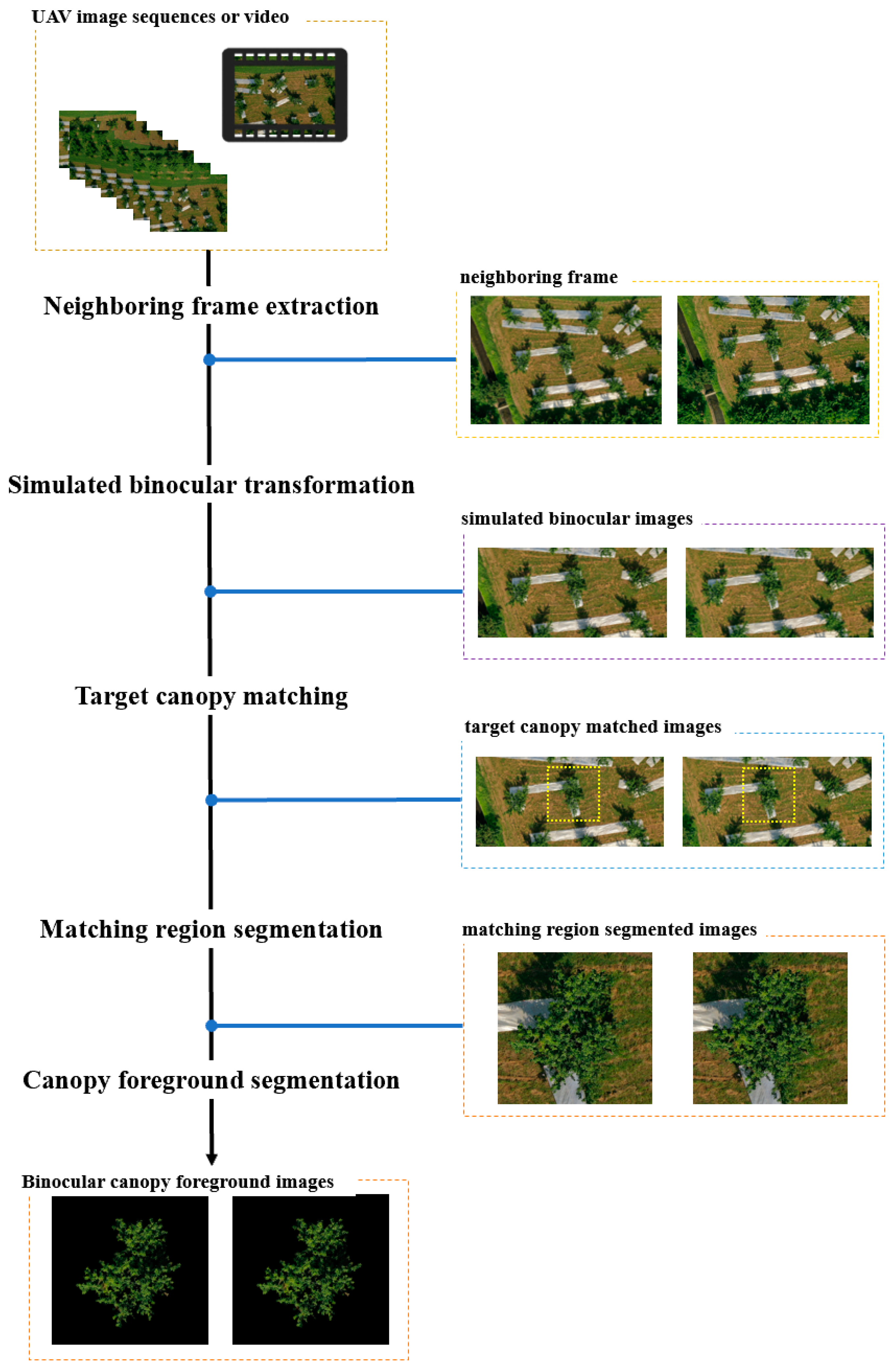
Before estimating the height of the fruit tree canopy, we preprocessed the UAV image sequence to generate a standard binocular CFM-RGB to facilitate subsequent canopy height estimation work. The preprocessing process of this module is as follows (shown in Figure A1):
Figure A1. Fruit tree CFM-RGB generation module workflow.
Remotesensing 16 01570 g0a1
  • Neighboring frame extraction: Extract neighboring frame images from UAV aerial videos or image sequences.
  • Simulate binocular transformation: Since the UAV trajectory may not be parallel to the camera lens CMOS sensor, it is necessary to convert the adjacent frames into a standard binocular image. This paper provides two transformations for simulating standard binocular photography, and the details of the process are as follows:
    • Known camera lens attitude: The attitude of the lens while capturing UAV photographs can be obtained from the UAV aerial photography log. According to the rotation angle α of the horizontal direction of the camera lens, rotate the neighboring frames of the image and crop out the redundant boundaries; thus, the form of the standard binocular image can be obtained.
    • Unknown camera lens attitude: If the attitude of the UAV camera lens is unknown, the rotation angle α can be calculated based on binocular feature point matching, and the standard binocular image form can be obtained by rotating the neighboring frame images according to the rotation angle α and cropping out the redundant boundary.
  • Target canopy matching: In this study, we used high-dimensional feature template matching to match the uniform canopy object in the binocular image, and we were able to determine the region of the uniform canopy object in the binocular map.
  • Matching region segmentation: The matching region of the same fruit tree canopy in the binocular image is segmented.
  • Canopy foreground segmentation: In order to reduce the impact of the ground background region on the subsequent process of fruit tree canopy height estimation, this module uses the foreground segmentation network (in this paper, we use the U2-Net) to realize the separation of the front background of the fruit tree canopy.

Appendix A.1.2. Canopy Structure Reconstruction Module

The measurement of fruit tree canopy structural characteristic parameters is based on the 3D structure of fruit tree canopies. This module recovers the 3D point clouds of fruit tree canopies from the CHM obtained from the canopy height calculation module in Section 2.2.2 and calculates the characteristic parameters of a canopy on the basis of the 3D point cloud of the canopy, and the structural restoration process of the canopy is shown in Figure A2.
According to the h m a x recorded in the process of canopy height estimation in Section 2.2.2 of the main text, we determined the true canopy height corresponding to each grey level in the high-quality CHM output from the canopy height calculation network and then reconstructed the canopy point clouds for the left and right eyes, respectively, according to the principle of small-hole imaging so as to obtain the canopy point clouds p c _ l and p c _ r , align and merge the two pieces of point clouds in the 3D space, and carry out smoothing processing on the merged point clouds (z-direction mean processing of point clouds at the same horizontal position) to obtain the final 3D point cloud p c of the canopy.
Figure A2. Schematic diagram of the restoration of the 3D structure of the fruit tree canopy.
Remotesensing 16 01570 g0a2

Appendix A.2. Canopy Structure Parameter Error Rates (Absolute Values) for the Proposed Method, the SFM+MVS Method, and Ground Truth

Table A1. Error rates (absolute values) between the canopy structure parameters measured using proposed method and the SFM+MVS method and the ground truth based on a summer fruit tree canopy with leaf cover.
CH (mm)
Tree_NumGTOur MethodSFM+MVSError_Our MethodError_SFM+MVS
BC13291.99983180.43542643.09543.389%19.712%
BC23296.99713161.14173481.79834.121%5.605%
BC33493.99953389.7183780.9522.985%8.213%
BC42644.99662731.06782773.58543.254%4.862%
BC52705.99752592.06672167.68854.210%19.893%
BC63050.99872992.44422744.83811.919%10.035%
BC72990.99732843.45582763.00194.933%7.623%
BC82583.99962546.85672197.5911.437%14.954%
BC92954.99802882.57613045.10622.451%3.049%
BC102892.99773036.54822716.98244.962%6.084%
BC113206.99693134.60842922.39922.257%8.874%
BC123138.99993024.78642969.26623.639%5.407%
Average 3.296%9.526%
CV (mm3)
Tree_NumGTOur MethodSFM+MVSerror_Our Methoderror_SFM+MVS
BC172,988,178,18478,534,836,96731,289,459,4927.599%57.131%
BC255,946,120,75451,911,611,87425,312,103,7727.211%54.756%
BC355,218,551,77950,042,335,36831,180,146,5709.374%43.533%
BC448,632,835,77544,404,385,16519,454,252,0478.695%59.998%
BC536,500,327,83531,794,054,22717,249,641,22712.894%52.741%
BC639,610,631,52736,172,979,00521,360,270,9018.679%46.074%
BC739,052,282,76535,616,992,14018,155,816,9938.797%53.509%
BC852,181,807,54346,413,451,78123,608,660,17411.054%54.757%
BC960,609,531,27555,582,427,18025,678,835,5658.294%57.632%
BC1060,231,686,91854,224,943,03734,921,278,3359.973%42.022%
BC1151,930,116,26955,804,523,50829,566,996,4237.461%43.064%
BC1229,354,802,48231,931,216,92717,505,795,2328.777%40.365%
Average 9.067%50.465%
CW (mm)
Tree_NumGTOur MethodSFM+MVSerror_Our Methoderror_SFM+MVS
BC18897.16159107.18217778.52012.361%12.573%
BC28349.00198105.69217548.21312.914%9.591%
BC37238.94716925.43616423.67684.331%11.262%
BC48635.55248798.56157110.00291.888%17.666%
BC57194.31356848.85496817.73994.802%5.234%
BC68179.37718419.18077694.86202.932%5.924%
BC76737.57637018.00285716.55464.162%15.154%
BC88297.68038228.96726716.77660.828%19.052%
BC97299.59987120.36616409.42242.455%12.195%
BC108204.68018371.9316656.28832.038%18.872%
BC117155.16077227.69656593.32901.014%7.852%
BC126569.06046801.68525475.47853.541%16.647%
Average 2.772%12.669%
CPA (mm2)
Tree_NumGTOur MethodSFM+MVSerror_Our Methoderror_SFM+MVS
BC140,411,613.0642,341,991.3430,888,526.734.777%23.565%
BC235,585,441.1933,541,574.3629,086,505.215.744%18.263%
BC326,751,863.5924,484,852.4321065,443.248.474%21.256%
BC438,070,053.3039,520,878.1525,807,313.273.811%32.211%
BC526,422,989.6023,946,341.3323,729,254.569.373%10.195%
BC634,154,166.9536,186,193.3830,227,686.495.950%11.496%
BC723,174,513.5625,143,765.1916,682,915.498.497%28.012%
BC835,149,295.9334,569,563.8723,031,649.661.649%34.475%
BC927,202,031.8225,882,599.1120,972,056.824.850%22.903%
BC1034,365,806.9035,781,168.4622,618,691.964.119%34.183%
BC1126,136,174.6226,668,774.1522,192,832.342.038%15.088%
BC1222,029,759.1923,617,628.8615,305,495.507.208%30.524%
Average 5.541%23.514%

Appendix A.3. Winter Time Application
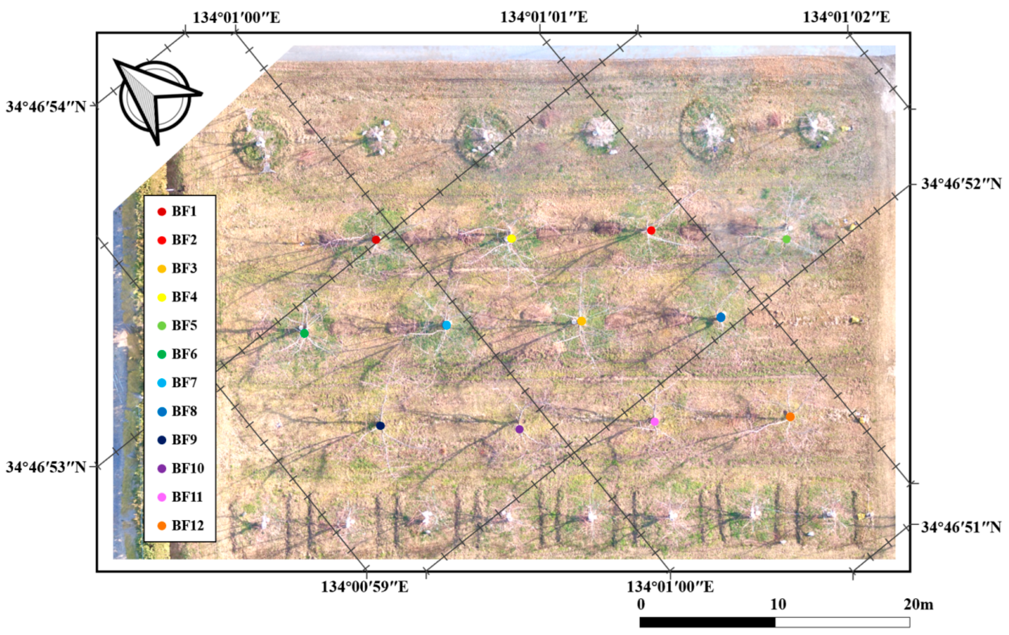
The flight was carried out in March 2018 over an orchard in Akaiwa, Okayama prefecture, Japan (34°46′52.9″N, 134°01′01.2″E). At the same time, a FARO Focus 3D Laser Scanner laser scanner was used to scan the 3D point cloud of this winter peach orchard in Okayama. Figure A3 shows an orthophoto image of the experimental field in Okayama prefecture.
Figure A3. DOM (Digital Orthographic Map) and peach tree object labels (BF1–BF12) of experimental field in Okayama prefecture.
Remotesensing 16 01570 g0a3
Figure A4. Comparison between the canopy structure parameters measured using the proposed method and the SFM+MVS method and the truth value based on a winter fruit tree canopy without leaf cover. (a) Comparison of CH. (b) Comparison of CV. (c) Comparison of CW. (d) Comparison of CPA.
Remotesensing 16 01570 g0a4
Figure A5. Comparison of the linear correlations between the canopy structure parameters measured using the proposed method and the SFM+MVS method and their truth values based on a winter fruit tree canopy without leaf cover. (a) Comparison of CH. (b) Comparison of CV. (c) Comparison of CW. (d) Comparison of CPA.
Remotesensing 16 01570 g0a5aRemotesensing 16 01570 g0a5b
Table A2. Error rates (absolute values) between the canopy structure parameters measured using proposed method and the SFM+MVS method and the ground truth based on a winter fruit tree canopy without leaf cover.
CH (mm)
Tree_NumGTOur MethodSFM+MVSError_Our MethodError_SFM+MVS
BF14484.980504618.5095169.9012.977%15.271%
BF24331.699374424.68154073.06182.147%5.971%
BF34360.799794502.23213770.41233.243%13.539%
BF44746.902474681.10865517.47421.386%16.233%
BF54175.704964092.51674544.53421.992%8.833%
BF64905.899054851.66345298.62951.106%8.005%
BF74717.597964559.84035621.19423.344%19.154%
BF84128.700264195.35214171.50541.614%1.037%
BF95077.598575185.17815536.74872.119%9.043%
BF104382.095344432.11855041.56321.142%15.049%
BF115107.994085226.10244316.46062.312%15.496%
BF124266.700754217.53664173.96111.152%2.174%
Average 2.044%10.817%
CV (mm3)
Tree_NumGTOur MethodSFM+MVSerror_Our Methoderror_SFM+MVS
BF1136,229,237,885133,655,821,17594,728,440,0931.889%30.464%
BF2136,613,113,912131,467,520,47389,458,954,3983.766%34.517%
BF3147,484,106,788148,983,106,91397,456,201,9581.016%33.921%
BF4139,481,684,081137,920,598,68885,926,643,8511.118%38.395%
BF5114,622,326,464106,985,450,08775,644,170,4446.662%34.006%
BF6205,824,240,590191,391,325,177127,680,818,5517.012%37.966%
BF7152,807,118,136155,486,208,77485,291,725,4181.753%44.183%
BF8115,944,151,016112,997,614,84673,508,895,4232.541%36.600%
BF9177,349,329,903189,563,398,636116,836,062,6766.887%34.121%
BF10137,619,496,656127,814,375,44993,184,910,9867.124%32.288%
BF11178,161,183,739194,327,302,860102,912,299,9409.074%42.236%
BF12110,476,314,241101,518,577,78878,535,122,8368.108%28.912%
Average 4.746%35.634%
CW (mm)
Tree_NumGTOur MethodSFM+MVSerror_Our Methoderror_SFM+MVS
BF110034.828879808.05487927.47682.260%21.000%
BF210472.588359987.91038051.32894.628%23.120%
BF39698.440709220.47196987.59754.928%27.951%
BF49485.525719202.1287186.92222.988%24.233%
BF58848.542808674.12666989.15351.971%21.014%
BF610574.1906510077.62827977.60134.696%24.556%
BF79685.146309508.44127049.76871.824%27.211%
BF88794.727708994.97846217.59312.277%29.303%
BF910297.732179877.87087934.23534.077%22.952%
BF109595.502219238.70746781.92273.718%29.322%
BF1110089.132859845.36257600.52762.416%24.666%
BF129132.319199409.22686995.28763.032%23.401%
Average 3.235%24.894%
CPA (mm2)
Tree_NumGTOur MethodSFM+MVSerror_Our Methoderror_SFM+MVS
BF151,407,108.7749,109,894.9832,082,868.964.469%37.591%
BF255,990,107.8650,927,517.2733,093,170.39.042%40.895%
BF348,018,331.7343,401,979.2824,926,367.849.614%48.090%
BF445,933,130.8843,229,456.7426,368,724.645.886%42.593%
BF539,971,159.8138,410,923.6824,937,470.293.903%37.611%
BF657,081,780.451,846,554.6132,489,863.989.171%43.082%
BF747,886,777.146,155,332.9725,371,899.033.616%47.017%
BF839,486,444.7541,305,081.919,735,486.284.606%50.020%
BF954,136,032.349,811,534.4932,137,596.217.988%40.635%
BF1047,004,415.6543,573,822.8623,480,584.787.298%50.046%
BF1151,964,998.4949,484,212.1829,491,082.824.774%43.248%
BF1242,576,053.4945,197,156.424,981,262.746.156%41.326%
Average 6.377%43.513%
Figure A6. Visualization results of the comparison between the canopy structure of fruit trees reconstructed using the proposed method and SFM+MVS method and its terrestrial Lidar scanning point cloud (in the case of peach tree canopy No. BF3). (a) Structure of ground-based Lidar scanning point cloud. (b) Canopy point cloud structure reconstructed using the proposed method. (c) Canopy point cloud structure reconstructed using the SFM+MVS method.
Remotesensing 16 01570 g0a6
Table A3. Comparison of the time and number of images required to reconstruct the canopy structure of 12 fruit trees with SFM+MVS based on the canopy scene of fruit trees with no leaf cover in winter(↓: The reduction ratio of the proposed method compared to the SFM+MVS method).
MethodReconstruction TimeAverage Reconstruction Time/TreeNumber of Images Needed for Reconstruction/Picture
SFM+MVS01 h:33 m:04 s266 s130
Our method6 m (↓88.7%)30 s (↓88.7%)24 (↓81.5%)

References

  1. Anthony, B.M.; Minas, I.S. Optimizing peach tree canopy architecture for efficient light use, increased productivity and improved fruit quality. Agronomy 2021, 11, 1961. [Google Scholar] [CrossRef]
  2. Anderson, N.T.; Walsh, K.B.; Wulfsohn, D. Technologies for forecasting tree fruit load and harvest timing—From ground, sky and time. Agronomy 2021, 11, 1409. [Google Scholar] [CrossRef]
  3. Ortenzi, L.; Violino, S.; Pallottino, F.; Figorilli, S.; Vasta, S.; Tocci, F.; Antonucci, F.; Imperi, G.; Costa, C. Early estimation of olive production from light drone orthophoto, through canopy radius. Drones 2021, 5, 118. [Google Scholar] [CrossRef]
  4. Jiang, H.; Liu, L.; Liu, P.; Wang, J.; Zhang, X.; Gao, D. Online calculation method of fruit trees canopy volume for precision spray. Nongye Jixie Xuebao/Trans. Chin. Soc. Agric. Mach. 2019, 50, 120–129. [Google Scholar]
  5. Gu, C.; Zhai, C.; Wang, X.; Wang, S. Cmpc: An innovative lidar-based method to estimate tree canopy meshing-profile volumes for orchard target-oriented spray. Sensors 2021, 21, 4252. [Google Scholar] [CrossRef] [PubMed]
  6. Radoglou-Grammatikis, P.; Sarigiannidis, P.; Lagkas, T.; Moscholios, I. A compilation of UAV applications for precision agriculture. Comput. Netw. 2020, 172, 107148. [Google Scholar] [CrossRef]
  7. Aslan, M.F.; Durdu, A.; Sabanci, K.; Ropelewska, E.; Gültekin, S.S. A comprehensive survey of the recent studies with UAV for precision agriculture in open fields and greenhouses. Appl. Sci. 2022, 12, 1047. [Google Scholar] [CrossRef]
  8. Bouguettaya, A.; Zarzour, H.; Kechida, A.; Taberkit, A.M. Deep learning techniques to classify agricultural crops through UAV imagery: A review. Neural Comput. Applications 2022, 34, 9511–9536. [Google Scholar] [CrossRef]
  9. Slavík, M.; Kuželka, K.; Modlinger, R.; Tomášková, I.; Surový, P. UAV laser scans allow detection of morphological changes in tree canopy. Remote Sens. 2020, 12, 3829. [Google Scholar] [CrossRef]
  10. Hyyppä, E.; Yu, X.; Kaartinen, H.; Hakala, T.; Kukko, A.; Vastaranta, M.; Hyyppä, J. Comparison of backpack, handheld, under-canopy UAV, and above-canopy UAV laser scanning for field reference data collection in boreal forests. Remote Sens. 2020, 12, 3327. [Google Scholar] [CrossRef]
  11. Chisholm, R.A.; Cui, J.; Lum, S.K.; Chen, B.M. UAV LiDAR for below-canopy forest surveys. J. Unmanned Veh. Syst. 2013, 1, 61–68. [Google Scholar] [CrossRef]
  12. Ghanbari Parmehr, E.; Amati, M. Individual tree canopy parameters estimation using UAV-based photogrammetric and LiDAR point clouds in an urban park. Remote Sens. 2021, 13, 2062. [Google Scholar] [CrossRef]
  13. Sun, G.; Wang, X.; Yang, H.; Zhang, X. A canopy information measurement method for modern standardized apple orchards based on UAV multimodal information. Sensors 2020, 20, 2985. [Google Scholar] [CrossRef] [PubMed]
  14. Mu, Y.; Fujii, Y.; Takata, D.; Zheng, B.; Noshita, K.; Honda, K.; Ninomiya, S.; Guo, W. Characterization of peach tree crown by using high-resolution images from an unmanned aerial vehicle. Hortic. Res. 2018, 5, 74. [Google Scholar] [CrossRef] [PubMed]
  15. Hao, J.; Fang, Z.; Wu, B.; Liu, S.; Ma, Y.; Pan, Y. Tree Canopy Height Estimation and Accuracy Analysis Based on Uav Remote Sensing Images. The International Archives of the Photogrammetry. Remote Sens. Spat. Inf. Sci. 2022, 43, 129–134. [Google Scholar]
  16. Nasiri, V.; Darvishsefat, A.A.; Arefi, H.; Pierrot-Deseilligny, M.; Namiranian, M.; Le Bris, A. Unmanned aerial vehicles (UAV)-based canopy height modeling under leaf-on and leaf-off conditions for determining tree height and crown diameter (case study: Hyrcanian mixed forest). Can. J. For. Res. 2021, 51, 962–971. [Google Scholar] [CrossRef]
  17. Krause, S.; Sanders, T.G.; Mund, J.P.; Greve, K. UAV-based photogrammetric tree height measurement for intensive forest monitoring. Remote Sens. 2019, 11, 758. [Google Scholar] [CrossRef]
  18. Hobart, M.; Pflanz, M.; Weltzien, C.; Schirrmann, M. Growth height determination of tree walls for precise monitoring in apple fruit production using UAV photogrammetry. Remote Sens. 2020, 12, 1656. [Google Scholar] [CrossRef]
  19. Malekabadi, A.J.; Khojastehpour, M.; Emadi, B. Disparity map computation of tree using stereo vision system and effects of canopy shapes and foliage density. Comput. Electron. Agric. 2019, 156, 627–644. [Google Scholar] [CrossRef]
  20. Ni, Z.; Burks, T.F. 3D dense reconstruction of plant or tree canopy based on stereo vision. Agricultural Engineering International. CIGR J. 2018, 20, 248–260. [Google Scholar]
  21. Zhang, R.; Lian, S.; Li, L.; Zhang, L.; Zhang, C.; Chen, L. Design and experiment of a binocular vision-based canopy volume extraction system for precision pesticide application by UAVs. Comput. Electronics in Agriculture 2023, 213, 108197. [Google Scholar] [CrossRef]
  22. Matsuura, Y.; Heming, Z.; Nakao, K.; Qiong, C.; Firmansyah, I.; Kawai, S.; Yamaguchi, Y.; Maruyama, T.; Hayashi, H.; Nobuhara, H. High-precision plant height measurement by drone with RTK-GNSS and single camera for real-time processing. Sci. Rep. 2023, 13, 6329. [Google Scholar] [CrossRef] [PubMed]
  23. Hirschmuller, H. Accurate and efficient stereo processing by semi-global matching and mutual information. In Proceedings of the 2005 IEEE Computer Society Conference on Computer Vision and Pattern Recognition (CVPR’05), San Diego, CA, USA, 20–25 June 2005; Volume 2, pp. 807–814. [Google Scholar]
  24. Hamzah, R.A.; Abd Rahim, R.; Noh, Z.M. Sum of absolute differences algorithm in stereo correspondence problem for stereo matching in computer vision application. In Proceedings of the 2010 3rd International Conference on Computer Science and Information Technology, Chengdu, China, 9–11 July 2010; Volume 1, pp. 652–657. [Google Scholar]
  25. Stateras, D.; Kalivas, D. Assessment of olive tree canopy characteristics and yield forecast model using high resolution UAV imagery. Agriculture 2020, 10, 385. [Google Scholar] [CrossRef]
  26. Raman, M.G.; Carlos, E.F.; Sankaran, S. Optimization and evaluation of sensor angles for precise assessment of architectural traits in peach trees. Sensors 2022, 22, 4619. [Google Scholar] [CrossRef] [PubMed]
  27. Chen, R.; Zhang, C.; Xu, B.; Zhu, Y.; Zhao, F.; Han, S.; Yang, G.; Yang, H. Predicting individual apple tree yield using UAV multi-source remote sensing data and ensemble learning. Comput. Electron. Agric. 2022, 201, 107275. [Google Scholar] [CrossRef]
  28. Sanz, R.; Llorens, J.; Escolà, A.; Arnó, J.; Planas, S.; Román, C.; Rosell-Polo, J.R. LIDAR and non-LIDAR-based canopy parameters to estimate the leaf area in fruit trees and vineyard. Agric. For. Meteorol. 2018, 260, 229–239. [Google Scholar] [CrossRef]
  29. Zhu, W.; Sun, Z.; Peng, J.; Huang, Y.; Li, J.; Zhang, J.; Yang, B.; Liao, X. Estimating maize above-ground biomass using 3D point clouds of multi-source unmanned aerial vehicle data at multi-spatial scales. Remote Sens. 2019, 11, 2678. [Google Scholar] [CrossRef]
  30. Kameyama, S.; Sugiura, K. Estimating tree height and volume using unmanned aerial vehicle photography and SfM technology, with verification of result accuracy. Drones 2020, 4, 19. [Google Scholar] [CrossRef]
  31. Straffelini, E.; Cucchiaro, S.; Tarolli, P. Mapping potential surface ponding in agriculture using UAV-SfM. Earth Surf. Process. Landf. 2021, 46, 1926–1940. [Google Scholar] [CrossRef]
  32. Miraki, M.; Sohrabi, H.; Fatehi, P.; Kneubuehler, M. Individual tree crown delin-eation from high-resolution UAV images in broadleaf forest. Ecol. Inform. 2021, 61, 101207. [Google Scholar] [CrossRef]
  33. Sun, G.; Wang, X.; Ding, Y.; Lu, W.; Sun, Y. Remote measurement of apple orchard canopy information using unmanned aerial vehicle photogrammetry. Agronomy 2019, 9, 774. [Google Scholar] [CrossRef]
  34. Scalisi, A.; McClymont, L.; Peavey, M.; Morton, P.; Scheding, S.; Un-derwood, J.; Goodwin, I. Detecting, mapping and digitising canopy geometry, fruit number and peel colour in pear trees with different architecture. Sci. Hortic. 2024, 326, 112737. [Google Scholar] [CrossRef]
  35. López-Granados, F.; Torres-Sánchez, J.; Jiménez-Brenes, F.M.; Arquero, O.; Lovera, M.; de Castro, A.I. An efficient RGB-UAV-based platform for field almond tree phenotyping: 3-D architecture and flowering traits. Plant Methods 2019, 15, 160. [Google Scholar] [CrossRef] [PubMed]
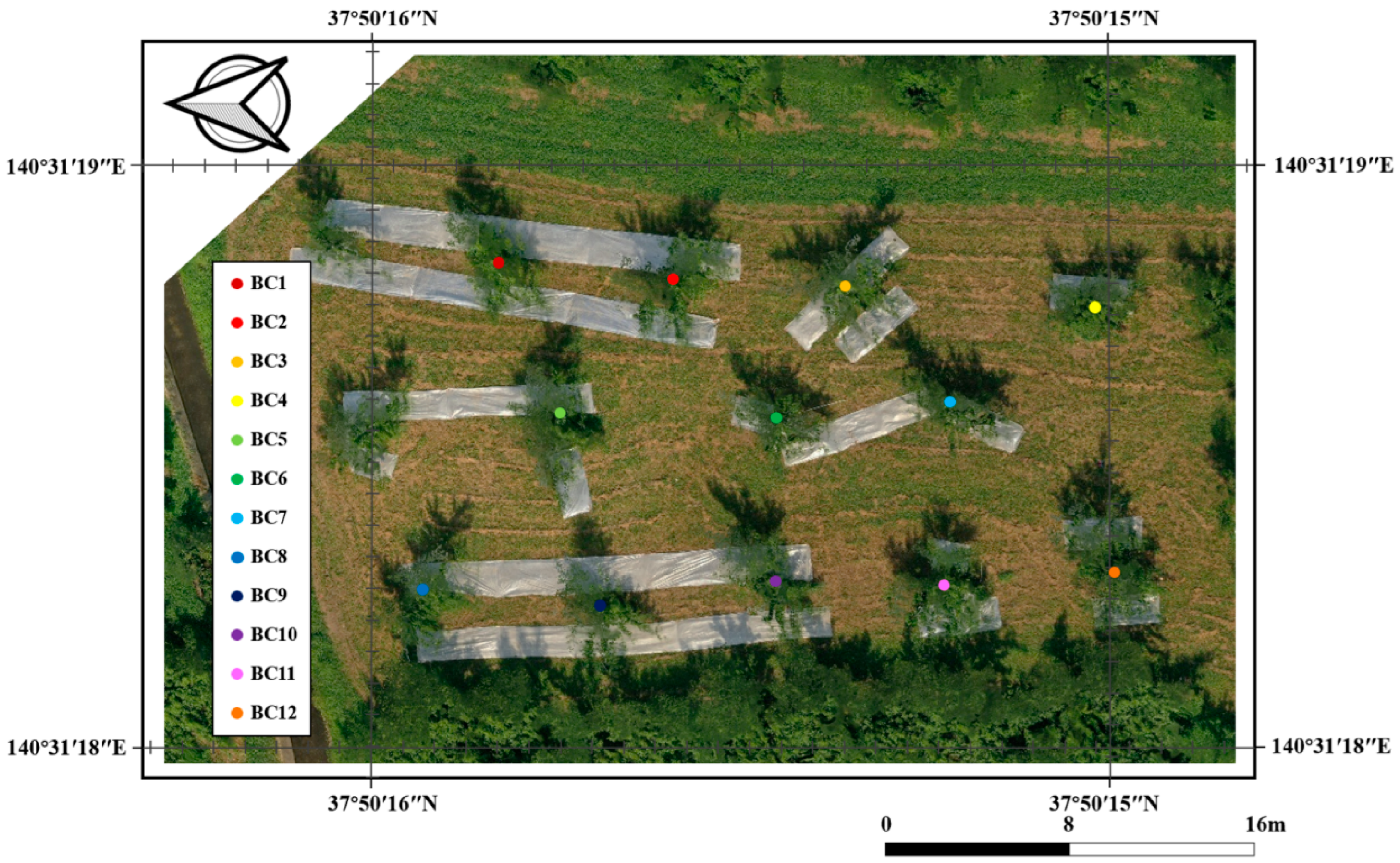
Figure 1. The experiment field in Fukushima prefecture.
Remotesensing 16 01570 g001
Figure 2. General framework of the methodology of this study. (a) Canopy foreground RGB map (CFM-RGB). (b) Canopy-height-estimated map (CHM-estimated). (c) Canopy height map (CHM).
Remotesensing 16 01570 g002
Figure 3. Higher similarity between binocular images for the same region of the canopy and lower similarity between different regions in the binocular images.
Remotesensing 16 01570 g003
Figure 4. Architecture of the canopy height estimation method based on block structure similarity. (a) Process of calculating binocular block similarity. (b) Process of calculating canopy height h at a block.
Remotesensing 16 01570 g004
Figure 5. CFM-RGB (a), block delineation image of canopy foreground area (b), and CHM-estimated map (c).
Remotesensing 16 01570 g005
Figure 6. Flowchart of training network used for calculating foreground height of fruit tree canopies.
Remotesensing 16 01570 g006
Figure 7. Generator structure of the canopy height calculation network.
Remotesensing 16 01570 g007
Figure 8. Canopy foreground region of generated CHM vs. label CHM and the number of height values within the region statistics. (a) Generated CHM vs. label CHM in the foreground region. (b) Distribution of the number of height values within the canopy foreground region for generated CHM versus label CHM.
Remotesensing 16 01570 g008
Figure 9. Schematic representation of the distribution distances of the heights of a level of the canopy in the CHM (a) and statistics of the distribution distances of height values of the CHM in the foreground region of the canopy (b).
Remotesensing 16 01570 g009
Figure 10. Comparison of CHM images and details before and after adding lossQD to the generator’s loss function for the same training rounds. (a) CHM generated without adding lossQD. (b) CHM generated after adding lossQD. (c) Label CHM.
Remotesensing 16 01570 g010
Figure 11. Schematic diagram of canopy structural parameters. (a) Canopy height, CH. (b) Canopy width, CW. (c) Canopy projected area, CPA. (d) Canopy volume, CV.
Remotesensing 16 01570 g011
Figure 12. Comparison between the canopy structure parameters measured using the present and SFM+MVS methods and the ground truth. (a) Comparison of CH. (b) Comparison of CV. (c) Comparison of CW. (d) Comparison of CPA.
Remotesensing 16 01570 g012
Figure 13. Comparison of the linear correlation between the canopy structure parameters measured using the proposed method and the SFM+MVS method and their true values. (a) Comparison of CH. (b) Comparison of CV. (c) Comparison of CW. (d) Comparison of CPA.
Remotesensing 16 01570 g013
Figure 14. Visualization results of the comparison between the canopy structure of fruit trees reconstructed using the proposed method and SFM+MVS method and its terrestrial laser scanner (TLS)-derived point cloud (in the case of peach tree canopy No. BC4). (a) Structure of terrestrial-laser-scanner-scanned point cloud. (b) Canopy point cloud structure reconstructed using the proposed method. (c) The canopy point cloud structure reconstructed using the SFM+MVS method.
Remotesensing 16 01570 g014
Table 1. The comparison of the time and the number of images required to reconstruct the canopy structures of 12 fruit trees between the proposed method and the SFM+MVS method(↓: The reduction ratio of the proposed method compared to the SFM+MVS method).
MethodSFM+MVSOur Method
Reconstruction time02 h:06 m:04 s6 m (↓95.2%)
Average reconstruction time/tree630 s30 s (↓95.2%)
Number of images needed for reconstruction/picture20324 (↓88.2%)
Disclaimer/Publisher’s Note: The statements, opinions and data contained in all publications are solely those of the individual author(s) and contributor(s) and not of MDPI and/or the editor(s). MDPI and/or the editor(s) disclaim responsibility for any injury to people or property resulting from any ideas, methods, instructions or products referred to in the content.