Abstract
In this paper, the application is investigated of fast Fourier transform filtering (FFT-FR) to high spatial resolution digital terrain models (HR-DTM) derived from LiDAR sensors, assessing its efficacy in identifying genuine relief elements, including both natural geological features and anthropogenic landforms. The suitability of the derived filtered geomorphic references (FGRs) is evaluated through spatial correlation with ground truths (GTs) extracted from the topographical and geological geodatabases of Santander Bay, Northern Spain. In this study, it is revealed that existing artefacts, derived from vegetation or human infrastructures, pose challenges in the units’ construction, and large physiographic units are better represented using low-pass filters, whereas detailed units are more accurately depicted with high-pass filters. The results indicate a propensity of high-frequency filters to detect anthropogenic elements within the DTM. The quality of GTs used for validation proves more critical than the geodatabase scale. Additionally, in this study, it is demonstrated that the footprint of buildings remains uneliminated, indicating that the model is a poorly refined digital surface model (DSM) rather than a true digital terrain model (DTM). Experiments validate the DTM’s capability to highlight contacts and constructions, with water detection showing high precision (≥60%) and varying precision for buildings. Large units are better captured with low filters, whilst high filters effectively detect anthropogenic elements and more detailed units. This facilitates the design of validation and correction procedures for DEMs derived from LiDAR point clouds, enhancing the potential for more accurate and objective Earth surface representation.
1. Introduction
The compilation of representative inventories of natural phenomena has been a priority in science from the beginning of the last century, especially when the aim is to carry out an objective representation of the elements of the geodiversity [1]. More recently, in the field of natural hazards and risk analysis, the need for objective analysis has taken similar views [2,3,4,5], particularly if it affects the geomorphic variables present on the Earth’s surface [6,7]. The most typical data employed for geomorphic analysis are sourced from digital elevation models (DEMs) that represent the terrain geometry [8,9]. Depending on the type of terrain registered in the DEMs, they are named with the two different denominations of DTM or DSM [9]. DTM is used when considering a numerical representation of a naked topographic surface (e.g., a bare land surface, without trees, houses, etc.), while DSM implies the consideration of existing elevations in the relief, either due to vegetation or buildings [8]. DTMs are considered in a multitude of treatments within the geosciences, land use, and vegetation analyses [10,11,12]. These datasets are a valuable source of information frequently produced by national cartographic institutions, such as those developed by the Spanish National Geographic Institute (IGN), as demonstrated in various studies [13,14,15]. The data sources for DEM generation come from different remote sensing techniques [16] such as radio detecting and ranging (RADAR) measures; point-clouds extracted from aerial or satellite images treated by digital photogrammetrical techniques (DPT), or from light detection and ranging or laser imaging detection and ranging measurements (LiDAR). Various authors have proposed a wide diversity of remote sensing methodologies based on the analysis of the terrain geometry contained in DEMs, helping the objective representation of geomorphic features, such as trend removal algorithms [17]; openness [18]; topographical position index (TPI) [19,20]; or the use of fast Fourier transform filtering (FFT-FR) proposed by [15,21,22]. All are equally valid, although the FFT-FR requires the least computational cost to obtain objective relief references, being 60 times faster than the convolution method TPI or openness [15]. Moreover, using DTMs provided from LiDAR and/or aerial DPT point-clouds [15,21], FFT-FR provides identification of either small or large scale geomorphic features, facilitating the characterization of morphologies corresponding to high-frequency elevation elements belonging either to geomorphic features or vegetation [15]. In natural landscapes constructed without the morphological influence of vegetation, such as those presented by digital planetary elevation models (PDEMS according to [9]), FFT-FR offers enormous possibilities for mapping objective crater features and generating robust inventories [21]. Despite the good results offered by the method, a critical aspect to consider is the emergence of some undesirable effects of blurring and the generalization of feature boundaries. These effects appear when the features to be analyzed are small, and/or are located in close proximity to each other, such as aligned craters or small craters circumscribed by larger craters, like those existing in lunar and planetary scenarios [22]. However, the complementary application of other Geographical Information System (GIS) and image processing methods (G&RS) as singular point, aspect-slope, or edge limits zonings can resolve this softness [22]. Nevertheless, the suitability of this type of analysis depends substantially on the robustness of the DTMs employed. If a DTM includes noise derived from the existence of vegetation or anthropogenic features (called artefacts in [15]), the ability of such models to provide objective representations of the geomorphic features is diminished, making it difficult to apply such approaches to the characterization of these elements. Therefore, a method is required for determining the capabilities of DTMs to accurately represent terrain features, minimize the impact of noise and artefacts, and maintain the integrity of geomorphic boundaries. This method could be effectively provided by FFT-FR testing.
Another interesting aspect that is important to highlight originates from the validation of the results. Although FFT-FR offers enormous possibilities for highlighting any real geomorphic element located on the surface, the effectiveness of the method is assessed by comparing the results with measurable facts that are credible because they exist in the objective reality called ground truth (GT, according to [23,24]). Thus, in different works [21,22], the authors have used DEMs from synthetic terrain models (scenarios where the GT is derived from the same model, and it is possible to know the real footprint of the simulated relief). Obviously, this is carried out thanks to the filtered geomorphic references (FGRs) extracted from the FFT-FR, which allows the identification of features existing in the model. In other words, thanks to the FGRs, it has been possible to validate the GTs, and also to calculate the effect of inaccurate GTs in the validation [22], and therefore the suitability of the GT generator. Nonetheless, when working with GTs generated from other source datasets, the evaluation of the degree of reality contained in the GT is more complicated, so it is unclear if unsuccessful validations originate from the effects of the low predisposition of the filter to identify the reality or from a poorly designed GT. Although the adaptation of the FFT-FR to detect the existing relief has been demonstrated in [15], its applicability on the analysis of semi-urban areas (whose morphological reality is strongly influenced by the existence of geoforms and artefacts derived from vegetation, infrastructures, buildings, etc.) has not yet been evaluated. In addition, the application of the method to detect other surface morphologies or geologic units has not been tested either; thus, it is also worth evaluating its practicality. Finally, the last aspect that would be desirable to start evaluating is the use of the FFT-FR method for the construction of improved DTMs. Without entering into the discussion on the quality of the DTMs employed [25,26,27] and how filtering algorithms are applied to identify the information in the point-cloud not belonging to the terrain [28,29], FFT-FR can help identify the morphological boundaries of terrain elevations. These boundaries usually belong to the natural landscape and should be preserved after filtering, to obtain homogeneous mapping of terrain features.
The hypothesis contained in this paper is that it is possible to use the FFT-FR method, with appropriate modifications derived from the source of the point-cloud datasets employed, for filtering DEMs and detecting real landforms and artefacts existing on the Earth’s surface, thereby providing objective mapping of these elements. The main goal of this contribution is to show, through various examples, how FFT filtering is applied, demonstrating what type of objects can be identified. A second objective is to evaluate the role of the FFT-FR in the identification of other geological units with a real morphological basis, to address the relevance of the GT used in the validation. Finally, a third goal is to present an example of a more realistic geological unit GT and its implication in DTM validation. The databases used are presented in the Materials and Methods section. As FFT filtering is a technique with a non-simple numerical basis, the main fundamentals are also presented in this section. The experiments carried out to perform the analysis considered in each scenario are also presented in this section. The results are organized into sections, each dealing with the main outcomes from the experiments. Finally, the Discussion section presents the principal considerations and summarizes the key findings and main conclusions from the analyses.
2. Materials and Methods
The methodology is divided into different subsections. The first section presents the conceptual foundations of the technique. The subsequent subsection introduces the study area where the applied methodology has been tested, describing the geodatabase employed. The next subsection introduces the main lines followed in the methodological workflow of the experiments designed. Finally, the selected scenarios and the methodological modifications are applied in each case.
2.1. Background and Rationale for the Method
Fast Fourier transform-based tools have been used in geosciences for more than 40 years [21,30,31]. More specifically, in geomorphology, the contributions are oriented either to morphogenetic studies [32,33] or to identify geomorphic features [15,21,22,34]. In the above studies, the analyses are based on the treatment of the terrain geometry contained in a DEM. In the Geographical Information System (GIS) and remote sensing community, a DEM is understood as a digital representation of elevation values (e(⋅)) of a territory. Mathematically, elevations can be considered as the Cartesian coordinate (z) that is a dependent variable represented with respect to the independent magnitude space of the territory depicted in the DEM, and expressed by its coordinates x, y. Irrespective of the type of sensor used to quantize the elevation or altimetry [9,15,35], each pixel of a DEM contains 3D information discretized by the spatial resolution of the DEM (pixel size). Thus, the continuous variable elevation is transformed into a discrete variable whose values are recorded within the tessellation resolution (pixel size) of the DEM matrix. Therefore, the DEM is an image (a 2D matrix) with an attribute that reflects pixel elevation. Therefore, given an image f(x, y) with P columns and Q Rows, for x = 0, 1, 2, …, P − 1 and y = 0, 1, 2, …, Q − 1, i.e., where P x Q is the dimension of the raster, or the region occupied by it.
Analyzing the elevations depicted in a DEM along any row or column acyclic undulations with a large wavelength (λ) appear, where the fundamental cycle (λ0) tends towards infinity (λ0→∞). It is precisely in such situations where FFT offers the possibility of efficiently depicting the altitudes in the frequency domain. The discrete Fourier transform of such image is given by F(u,v), as follows:
for u = 0, 1, 2, …, P − 1 and v = 0, 1, 2, …, Q − 1.
All the relief elements present in the DEM will have a response in relation to their altimetric frequency thanks to the 2D FFT. That is, by transforming the DEM or image of elevations from a spatial domain to a frequency domain, we are able to filter the desired frequencies thanks to the application of a filtering method (high pass, low pass, band pass, etc.). Therefore, the general methodology begins by selecting an altimetric image, identifying the existing frequencies on the DEM, and selecting those to be used as cut-off frequencies (COFs) employing a certain criterion. Then, thanks to the 2DFFT and applying filtering through a circular mask whose radius has the same size as the COF (filter radius, FR), the desired sequences are extracted. Afterwards, the filtered matrix is inverted by means of the inverse of the transform (2DIFFT) to once more achieve an image expressed in the spatial domain, but without desired frequencies.
for x = 0, 1, 2, …, P − 1 and y = 0, 1, 2, …, Q − 1.
Details of the mathematical expression of any image representing the surface elevation in the space domain, its conversion to the frequency domain by means of 2DFFT, the application of Fourier filters using a possible FR (term equivalent to COF), and finally, the transformation of this signal back to a new image, are presented in [15] in addition to the expressions given in this description. Meanwhile, in [21,22], how use a true magnitude–true frequency plot to identify the existing frequencies in the image and the criteria used to select FRs; the method employed for performing a high pass filter (HPF) using selected FRs; the generation of the corresponding filtered geomorphic reference (FGR) and filtered models (FGRMs); and finally, how to validate FGRMs towards reliable GTs are presented.
2.2. Study Area and Datasets
The area selected for the designed experiments to be presented later is located within the Bay of Santander, Northern Spain (Figure 1), which spans a surface of 76 km2. The DTM employed for performing the experiments comes from the Spanish National Topographic Database (BTN) [36,37]. Figure 1a shows the range of heights found in this territory. By using a database developed in Spain, figures include the Spanish notation with decimal point and comma for thousands. This model originates from the 2nd LiDAR (acquired from 2015 to present) generated by the Spanish Instituto Geográfico Nacional with a mesh-hop of 2 m. The experiments that will be proposed in Scenario_1 start from the typical analysis of the territory carried out at a scale of 1/10,000. The following five land-use units were considered (Figure 1b): facilities; roads and infrastructures; buildings; natural slopes; and water bodies (either from the sea or interior). The elaboration of these units involves a progressive generalization to fit the scale. Some details about this database are presented in the literature [38,39] and there are also examples of its use in the analysis of territorial studies [40].
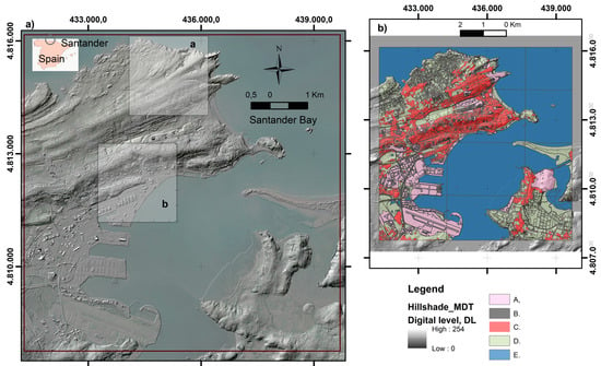
Figure 1.
Area selected in the three scenarios framed within Santander Bay (Zone_1). The heights proceed from a clip of the DTM called 9400_MDT02-ETRS89-HU30-0035-1-COB2.tif (IGN_2024) elaborated from the 2nd coverture LiDAR (acquired from 2015 to present). (a) Hillshade of the DTM used (the model has an ETRS89 geographic coordinate system with UTM planimetric projection). Inner line purple box corresponds to the area selected to carry out the experiments included in the scenarios 1 and 2. Grey boxes in this zone correspond to the areas selected in the Scenario_3 (a and b). (b) Principal land-use units considered in this study (A, facilities; B, roads and infrastructures; C, buildings; D, natural slopes; and E, water) extracted from BTN [36,37].
The geological units, validated in Scenario_2, were generated from the official geological cartography of the region at 1/25,000 scale [41,42]. The official geological map of Cantabria, “Mapa Geológico de Cantabria”, was elaborated at the beginning of this century by the Instituto Geológico y Minero de España (IGME) at the request of the Government of Cantabria. This database contains the following maps, among others: a geological map (litho-stratigraphical map), active processes, and geomorphology. In Scenario_3, a second geodatabase was considered to generate ad hoc geological units. The second geological database corresponds to the CIDS [43], which was elaborated in the 1980s. It was prepared at 1/50,000 scale to support the management and assessment of natural heritage and land-use evaluations for the Cantabrian Province. This inventory was carried out by the Universidad de Cantabria and the Consejo Superior de Investigaciones Científicas (CSIC). The geological variables included in the databases were the following: lithology (bedrocks and superficial deposits); geomorphology (including information on active processes and morphological features); and soils (typology using FAO classification, soil depths, soil limitations, and usage capacities). The accuracy of the map limits extracted from the geological units generated from this database was evaluated by means of digital stereoscopic models in a digital photogrammetric workstation supported by ERDAS-LPS.
Figure 2 displays the various ground truths (GTs) generated using the first two databases mentioned above. They were employed in experiments that compose scenarios 1 and 2. In the GTs (a, c, d, e, and f), the unit to be evaluated receives the value of 100 or 200; meanwhile, in the GT b, there are 3 units that receive values from 100 to 300. GTs employed in Scenario 3 will be presented later, and have the same units, whilst the GTs a and b and the units receive the same values.
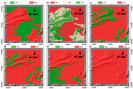
Figure 2.
Ground truths (GTs) utilized in scenarios 1 and 2. (a) Distinction between the ocean and continent (ocean valued as 100, continent valued as 200); (b) delineation of buildings and urban areas (buildings valued as 100, natural terrains valued as 200, water valued as 300); (c) identification of bedrock units (bedrocks valued as 100, remaining units valued as 200); (d) identification of superficial units (superficial units valued as 100, remaining units valued as 200); (e) identification of anthropic landscapes (anthropic landscapes valued as 100, remaining units valued as 200); (f) identification of dolines and karstic depressions (dolines and depressions valued as 100, remaining units valued as 200).
2.3. Methodological Structure of the Scenarios and Experiments
The present contribution applies the same methodological framework as in the preceding contributions [15,21,22]. The signal extracted from DEMs underwent filtering using HPF-FFT techniques. Through this filtering process, the FGR vectors were extracted and generated the corresponding FGRMs, facilitating their cartographic representation. Different methods can be used for extracting FGR, either using the ERDAS program image [21] or through the procedure described in [22], both of which provide consistent results. Subsequently, the results were compared against the GTs to assess the quality of the validation processes. GTs employed in this study were derived from the existing Geodatabases and/or ad hoc geomorphological treatment carried out with such information. In validation, the same accuracy tests were applied (global accuracy, GA, and kappa, k) as in the preceding contributions, whose description is also presented in the previous works.
Different scenarios are considered to fit the goals previously presented. The first scenario (Scenario_1) involves the analysis of how FFT-FR is performed to identify objects present in reality. This first test is proof that the method works. In this scenario (Experiment_1 and Experiment_2), all FRs are presented and their ability to identify the coast line (a linear feature that separates continent from the ocean) and buildings is assessed; in this case, the GT selected proceeds from the BTN [36]. In a second scenario (Scenario_2), the ability of FFT-FRs to identify other geological units strongly related with morphology is assessed (Experiment_3, Experiment_4 and experiment_6). The GTs employed proceed from the Geological database of Cantabria at 1/25,000 scale [41,42]. Finally, in the third scenario (Scenario_3), the capacity of an ad hoc GT elaborated from traditional geological techniques (bibliography, aerial photointerpretation, and fieldwork) is analyzed (Experiment_7 and Experiment_8). In this case, the main contacts were extracted from a new geodatabase elaborated in the 1980s, at 1/50,000 scale, called CID [43]. This new treatment was applied to a smaller area shown in Figure 1 and within Scenario_3. The mapping of such 3D features was extracted from a digital stereoscopic model created in a digital photogrammetric workstation equipped with the software ERDAS-LPS, V16.6, using the aerial images of the same epoch (2022) taken from the PNOA project; the contacts were mapped in 3D and revised with field data. New contacts were incorporated for some geomorphic elements, such as depressions, fields of dolines, and isolated dolines. A validation set for these elements was created comparing the last contacts with others extracted from combined processes that consider the 10 m buffers of the points generated by the ArcGIS peaks and hole functions. All geomorphic features considered were finally validated using typical photo-interpretation criteria based on the morphological correspondence between rock types and features.
3. Results
The results of the application of FFT-FR to the analysis of DTMs are presented in this section. The three scenarios selected to illustrate the suitability of the technique are composed of different experiments that are described in the methodology.
3.1. DTM Analysis and Filtering Limits Extraction
Figure 3 illustrates the distribution of heights depicted in the DTM of the area of Santander Bay selected to perform the different scenarios (Zone_1). Elevations in Zone_1 range from −24.8 m to 130.5 m (Figure 3a). The histogram of altitudes exhibits a left-skewed distribution, with a mode that is less than the mean (11.2 m) and a standard deviation of 16.9 m (Figure 3b). The histogram presents the frequency of occurrence of the 256 digital levels (DL) in which the DEM altimetry is categorized, providing an insight into the magnitude of each DL. The magnitude-true frequency plot (Figure 3c) displays the sets of elevations existing in the DEM matrix belonging to Zone_1. As indicated in the introduction, the altimetry is perceived as a wave with a fundamental cycle possessing a high amplitude and a very long period, causing its frequency to approach zero. There exist other clusters of elevations with progressively shorter periods, and higher frequencies but diminishing amplitudes. Figure 3c demonstrates the typical decreasing in the elevation magnitude as the frequency (cycles of altitude within the study area size) increases. The elevation histogram shows a similar pattern regarding the magnitude–true frequency plot. Following the recommendation of [22], the minimal frequencies selected are 1, 5, 7, 12, 21, 24, 28, 40, 60, and 91 (Figure 3d). These have been deemed as cut-off frequencies (COFs, also called filter radius, FR) for executing the FFT-FR filtering. To identify appropriately the influence of very low frequencies, an additional frequency of 0.001 has also been considered. It is important to note that the area covered by Zone_1 exceeds the area in which the scenarios are tested to obtain the broadest possible variation in altitude frequencies from the DTM. The elevations in the scenarios area range from −1.019 m to 52.87 m (Figure 3a).
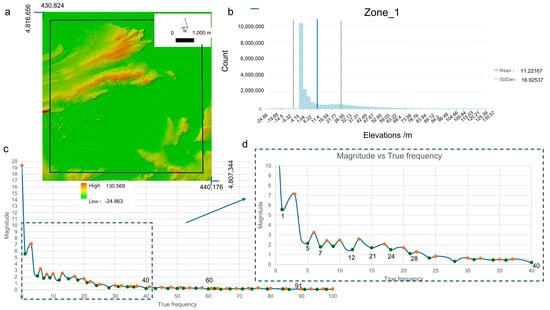
Figure 3.
Four aspects of the elevation analysis of the Santander Bay area (Zone_1) are presented. (a) The DTM utilized emphasizes elevations in a color range (−24.8 to 130.5 m), the black line box corresponds to the area selected in the three scenarios (the heights in this area ranging from −1.02 to 52.87 m); (b) a histogram depicting the distribution of elevations present in the Santander Bay area (mean and standard deviation are indicated); (c) a general view of the magnitude-true frequency plot, with cut-off frequencies (COFs) accentuated (green and orange dots are maximum and minimum of the main harmonics, respectively), the COF with figures are the filtered radius (FR) considered in this study; (d) a detailed view of the magnitude-true frequency plot, showcasing low and medium frequencies, with the COFs emphasized by figures.
Utilizing the aforementioned frequencies, various filtered geomorphic references (FGRs) were derived from the DTM through high pass filtering methods and a Butterworth transfer function (Figure 4). FGRs were obtained from low-frequency filters (ranging between 0.001 and 7 cycles), mid-frequency filters (spanning between 12 and 28 cycles), and high-frequency filters (extending between 40 and 91 cycles). The low-frequency FGRs distinctly delineated the boundaries between the continent and the ocean. Conversely, as the filter radius (FR) increased, the FGRs revealed details about other types of geomorphic elements present in the DTM, corresponding to the remaining real elements sculpted on the terrain surface.
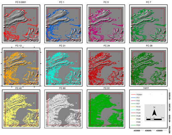
Figure 4.
A visual comparison of the filtered geomorphic references (FGRs) derived in the area of Santander Bay for each cut-off frequency (COF), or filter radius, (FR) is presented. Color vectors illustrate the FGR (in the legend, each FGR is identified as the frequency symbol, FC plus FR figure), all of which are displayed on a shaded relief extracted from Figure 1 and superimposed in black.
3.2. Results of the Scenario_1
In this scenario, the ability of the FFT-FR to characterize a clear and unambiguous unit that presents a distinct and absolute limit on altimetry is analyzed. The selected unit is the line that separates the continent from the ocean (coastline), which is primarily the ocean unit. Utilizing the land-use information procured from the BTN, an initial reclassification of the planimetric units was conducted. The five units previously considered (facilities; roads and infrastructures; buildings; natural slopes; and water bodies) were recombined to generate two types of GTs. The first GT (Figure 2a) considers a simple land-use unit that consists of the dichotomous class water-continent, segmenting the sea from the rest of the area.
GT models assign a value of 100 to the sea unit and 200 to the continent. Different filtered geomorphic reference models (FGRMs) were derived for each of the FGRs depicted in Figure 4, as shown in Figure 5. Filtered model units are assigned a value of 1 if they correspond to the equivalent category, and 2 otherwise. Thus, the sea is assigned a value of 1 and the continent a value of 2. The analysis conducted endeavors to identify which FGRMs are most suitable for distinguishing the sea from all others. The suitability of the spatial intersection between the FGRM and GT is included in Figure 5.
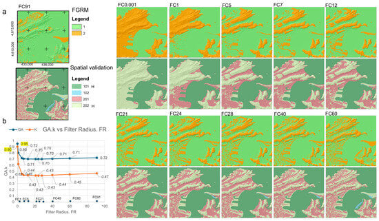
Figure 5.
A visual comparison is shown between the filtered geomorphic reference models (FGRMs) from Experiment_1 of Scenario_1 and the ground truth (GT) used to distinguish between continental and sea areas (Figure 2a). The figure is divided into the following subdivisions: (a) At the top of the rows, FGRMs for each filtering radius, FR (COF in the text), are indicated (each box considered includes the frequency symbol, FC, plus filter figure). The units represented are (1) area detected by the filter as water, and (2) area detected as continent; at the bottom of the rows, the corresponding validation model obtained appears (the spatial intersection units are 101, 102, 201, 202, with 101 and 202 being the hits (H), while the rest are failures). The four rows located at the right side show equivalent results obtained for each FR considered. (b) Global accuracy, GA, and kappa values obtained from each spatial intersection, emphasizing the FR offering the best accuracy indexes.
Four units are derived from the spatial intersection (101, 102, 201, and 202). As in the preceding works, 101 and 202 are hits, whereas 102 and 201 are failures. Information about their global accuracy (GA) and kappa indexes of the spatial intersection conducted between GT and FGRMs are also presented in Figure 5. All the accuracy indexes (GA and kappa) obtained for each experiment and scenario are presented in Supplementary Material A. Concerning Experiment_1 (Table S1a–k), two GT units were considered (sea and continent). The optimal validation occurs using the filter with the smallest FR, which is 0.001, yielding a GA exceeding 95% and a kappa value of 90%. These values indicate not only the close relationship between the filter and reality but also reflect that the filter is not derived by chance. The lowest values correspond with those FRs between 5 and 40, where filters begin to identify small continental units that disrupt the continuity of the coastline, resulting in a reduction in GA to 70%. However, their kappa decreases to 43% (demonstrating the diminished capacity of the filtering to specifically map these units). Filters up to 40 maintain GA values above 70% with a slight enhancement of the kappa value.
A new reclassification (Experiment_2) of the BTA was conducted to achieve a more realistic representation of the filter’s ability to detect anthropic boundaries. In addition to the units depicted in the previous GT, an extra unit termed building was incorporated (Figure 2b). In this instance, GT units alter their values, as follows: the sea unit is assigned a value of 300 and encompasses all types of waters (oceanic and continental); the continental units are assigned a value of 200 and correspond to natural landscapes; all infrastructures and roads were combined into a third class which is assigned a value of 100 and includes all types of constructions and intervening landscapes. The FGRMs were reclassified according to their vocation using the same criteria as those corresponding to buildings (value 1), natural landscape (value 2), or water units (value 3). On this occasion, the spatial intersection units are 101, 102, 103, 201, 202, 203, 301, 302, and 303. In such a situation, the hits are 101, 202, and 303, while the failures correspond to the remainder of the classes indicated (Figure 6). Once again, the most favorable indicators are achieved for the low-frequency filters (0.001–1 cycles) with values exceeding 0.74 GA and 0.60 kappa (all accuracy indexes are included in Table S2a–k, in Supplementary Material A). From this filter, up to a frequency of seven cycles, the values drop significantly to 0.62 GA and a kappa value of 0.35. These values suggest that the filters acquired offer low confidence in the contacts. From this frequency, the overall accuracy and kappa values begin to recover steadily and gradually, reaching a GA of 0.65 and a kappa of 0.42 when a frequency of 91 cycles is utilized. Producer accuracies are approximately 94% for the constructions and intervening landscapes unit, with user accuracies of 97%, while for the natural landscape class, accuracies range from between 45% and less than 7%, respectively, values that contrast with those of the water class, which has user accuracies around 50%, and producer accuracies of less than 11%.
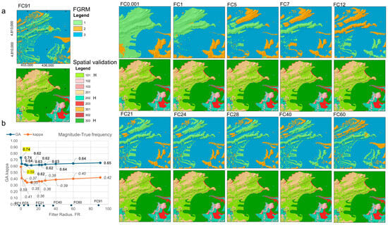
Figure 6.
Visual comparison between the filtered geomorphic reference models (FGRMs) and the spatial validation models derived for the analysis of three land use classes (Experiment_2, Scenario_1). (a) At the top of the rows, FGRMs for each filtering radius, FR (COF in the text), are indicated (each box considered includes the frequency symbol, FC, plus filter figure). The units represented are as follows: (1) area detected by the filter as buildings; (2) area detected as natural slopes; and (3) area detected as water. At the bottom of the rows, the derived validation models appear (the spatial intersection units are: 101, 102, 103, 201, 202, 203, 301, 302, 303, with 101, 202, and 303 being the hits or H, while the rest are failures). (b) Global accuracy, GA, and kappa values derived from each spatial intersection, emphasizing the FR offering the best accuracy indexes.
3.3. Results of the Scenario_2
In this scenario, the considerations and the focus have been modified regarding Scenario_1. In this case, an analysis of the capacity of different GTs is performed. The geological units considered in the GTs are extracted from the Geological Inventory of Cantabria at 1/25,000 scale [43] and the ability of these units to be objective references is analyzed. Thus, different types of GTs have been examined through the comparative response provided by the FGRMs. The aforementioned GTs were obtained by means of a reclassification of the existing information (Figure 2c–f). All the units present in the GT models have a morphological reflex. However, in the geological map, the information about these units sometimes comes from a purely semantic criterion, leading to identification problems. The following simple GT units were considered: location of bedrock outcrops (or bedrock units, Figure 2c); surface deposits (considering different types as beaches, subtidal, and intertidal materials, Figure 2d); anthropogenic relief (Figure 2e); and dolines and karstic depressions (Figure 2f). Different experiments compose this analysis, and all accuracy index values are included in the respective tables of Supplementary Material A (Table S3a–k). All generic illustrations are presented in Supplementary Material B, whilst the most representative are featured in the text.
Experiment_3 shows the correspondence between the GT elaborated using substrate units (Figure 2c) and FGRMs (Figure S1B, Supplementary Material B). As in the previous cases, the GT models have two classes. Bedrock outcrops receive the value of 100, while the rest of the units and water receive the value of 200. FGRMs also have two classes (value 1 for bedrock and value 2 for water). Following the same organization as in the previous examples, the units obtained through the spatial crossing between GT and FGRMs are valued as 101, 102, 201, and 202 (Figure 7). As in the above subsection, 101 and 202 are the hits, whereas 102 and 201 are failures, respectively. The results of the validation performed show how the oscillation in the GA values is between 0.79 and 0.91 (Table S3Aa–Ak, Supplementary Material A). The best result corresponds to a frequency of 12 cycles with a GA of 91% and a kappa of 72%. From that FR, the GAs reduce slightly to a value close to 86% for the rest of the frequencies. Nevertheless, kappa values reduce sharply from frequency 12 to 40, recovering 56% from that frequency and at higher frequencies.
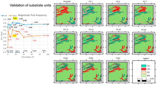
Figure 7.
Validation models obtained in Experiment_3 by the spatial crossing between the GT units of substrate rocks and corresponding FGRMs presented in Figure S1B. On the left, a true magnitude–frequency plot highlighting the result that offers the best accuracy indexes (global accuracy, GA, and kappa). Positions of the frequencies used in filtering or filter radius (FR) are introduced to aid identification. On the right, validation models obtained for each spatial crossing with the FGRMs considered. Filters are presented using acronyms FC plus FR (or filter figure).
In Experiment_4, the correspondence between the GT extracted from the surface units (Figure 2d) and FGRMs is presented (Figure S2B, Supplementary Material B). The model has two classes that differentiate between surface deposits and water. Surface units are beaches, sub- and intertidal deposits, slope deposits and colluviums, and soils, except lithosols. Similarly, as in the above experiment, the surface units received the value of 100, while the rest, including water, received the value of 200. The respective FGRM units (Figure S2B, Supplementary Material B) have a value between 1 and 2 (considering the respective surface deposits or hits and failures). Like the last experiment, the units obtained through the spatial crossing between GT and FGRMs are valued as 101, 102, 201, and 202 (Figure 8). The results of the validation performed show how the oscillation in the GA values is between 0.64 and 0.87 (Table S4a–k in Supplementary Material A). The best result corresponds to a frequency of 91 cycles, with a GA of 87% and a kappa of 37%. The rest of the frequencies show a GA over 80% except the filter obtained at the lowest frequency (64%). In any case, all filters offer minimal confidence because kappa values are below 35% except for the highest frequency filter.
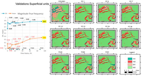
Figure 8.
Validation models obtained in Experiment_4 by the spatial crossing between the GT units of surface units and corresponding FGRMs presented in Figure 2d. On the left, a magnitude–frequency plot highlighting the result that offers the best accuracy indexes (global accuracy, GA, and kappa). Positions of the frequencies used in filtering or filter radius (FR) are introduced to aid identification. Filters are presented using acronyms FC plus FR (or filter figure).
The next experiment (Experiment_5) shows the ability of the geological database to provide information about artificial reliefs such as docks, dikes, wetland infills, etc. In this experiment, the anthropic units present in the GT (Figure 2e) receive the value 100, while the rest (including water) receive 200. The FGRM units were reclassified to identify this morphology and assume values equivalent to those of the previous experiments, as shown in Figure S3B (Supplementary Material B) and Figure 9. The accuracy indexes obtained (Table S5a–k in Supplementary Material A) show the capacity of the GTs to represent this relief unit. GA ranges in a narrow band between 0.83 and 0.88, while kappa values show a sharp oscillation between the low frequency filters (below 0.30) and high frequency filters (over 0.37). The best fit is obtained using a frequency of 28 cycles (with a GA of 88% and a kappa of 43%).
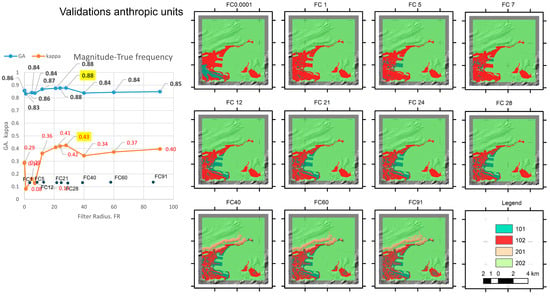
Figure 9.
Validation models obtained in Experiment_5 by the spatial crossing between the GT units of anthropic reliefs and corresponding FGRMs presented in Figure S3B. On the left, a magnitude-frequency plot highlighting the result that offers the best accuracy indexes (global accuracy, GA, and kappa). Positions of the frequencies used in filtering or filter radius (FR) are introduced to aid identification. Filters are presented using acronyms FC plus FR (or filter figure).
The last experiment (Experiment_6) is oriented to identify depressions generated by karstic processes. A set of karstic depressions and dolines were identified using the semantic information contained in the geological databases. In this case, GT units (Figure 2f) present the existence of such features. As mentioned above, units received the value of 100, while the rest, including water, received the value of 200. The respective FGRM units (Figure S4B) have a value between 1 and 2 (considering hits and failures, respectively). Like the rest of the experiments, units obtained through the spatial crossing between GT and FGRMs are valued as 101, 102, 201, and 202 (Figure 10). Accuracy indexes (Table S6a–k in Supplementary Material A) show values of GA close to 99%. However, kappa provides very low values between 0 and 29%. The user accuracies give high values (over 88%) for both elements. Nevertheless, producer accuracies reduce notably in the doline identification, being an unspecific method for those purposes.
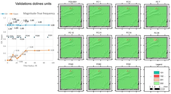
Figure 10.
Models obtained in Experiment_6 by the spatial crossing between the GT units of dolines and the corresponding FGRMs presented in Figure S4B. On the left, a magnitude–frequency plot highlighting the result that offers the best accuracy indexes (global accuracy, GA, and kappa). Positions of the frequencies used in filtering or filter radius (FR) are introduced to aid identification. F Filters are presented using acronyms FC plus FR (or filter figure).
3.4. Results of the Scenario_3
This scenario analyzes the capacity and limitations of ad hoc GTs as a formula to improve the objective mapping of geological units. In a small area of Zone_1 of about 4 km2, a more detailed geomorphological analysis has been carried out at a scale of 1/5000 (Experiment_7). The area selected is on the northern edge of the urbanized area (Figure 1, area a). Using the best results of the previous classifications in terms of the accuracy indexes, the coastline and the substrate models were selected as the background (Figure 2a,b). Then, following the traditional field and photointerpretation geological methods, a new GT was generated (Figure 11a). The model considers new geomorphic elements such as the coastline, isolated dolines, and fields of dolines (Figure 11c).
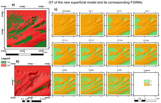
Figure 11.
Comparison between the GT of the new surface model and its corresponding FGRMs (Experiment_7). (a) A new GT model obtained for the surface units in the selected study area. (b) Detail of the GT model showing the incorporated geomorphic contacts (black lines) corresponding to the following elements: coastline, depressions, doline fields, and isolated dolines. (c) Filtered geomorphic reference modes (FGRMs) obtained by applying the FFT filters, whose filter radius (FR or cut-off frequencies) appear in the header. Filters are presented using acronyms FC plus FR (or filter figure).
The new surface units (Figure 11a) have two classes. The surface unit itself receives the value 100 while the rest (including water) receives 200. Obviously, the FGRM units obtained (Figure 11c) were reclassified to identify these morphologies, receiving values equivalent to those of the previous experiments. Validation models obtained by the spatial crossing of the new superficial units’ ground truth (GT) and the corresponding FGRMs are presented in Figure 12. Accuracy indexes obtained show (Table S7a–k in Supplementary Material A) the capacity of the new GT. GA ranges in a narrow band between 0.86 and 0.84, while kappa values show a drastic increase from low frequencies (close to 0) to high frequency filters (over 0.64). The best fit is obtained using a frequency of 60 (with a GA of 84% and a kappa of 66%).
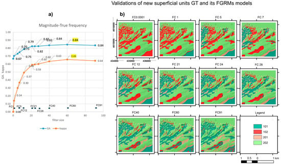
Figure 12.
Validation models obtained in Experiment_7 by the spatial crossing of the new surface units ground truth (GT) and the corresponding FGRMs presented in Figure 11c. On the left, a magnitude–frequency plot highlighting the result that offers the best accuracy indexes (global accuracy, GA, and kappa). Positions of the frequencies used in filtering or filter radius (FR) are introduced to help their identification. Filters are presented using acronyms FC plus FR (or filter figure).
Figure 13 shows the results of Experiment_8 that analyzes the control of the buildings and infrastructure in the DTM in a selected area of 4 km2 (Figure 1, area b). Figure 13a shows the GT generated from the BTA, which displays the buildings and construction units. The units follow the same criteria as presented above. Areas with buildings are classified with value 100, while the rest receive 200. Figure 13b presents the GT for a territory of 4 km2 located in the built-up area of Zone_1 (black box). Figure 13c shows only the validations performed with respect to the corresponding FGRMs and their corresponding accuracy indexes. Accuracy indexes obtained show (Table S8a–k in Supplementary Material A) the capacity of the new units.
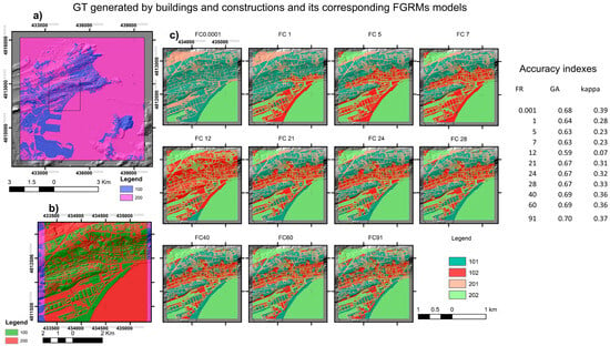
Figure 13.
Validation of the GT generated by buildings and constructions (Experiment_8) in an urban location (black box area B of Figure 1). The respective FGRMs obtained are not presented in the figure. Buildings have a value of 100, the remaining classes receive 200. (a) GT model obtained for this classification along Zone_1, where urban units have the value of 100 and the remaining receive 200. (b) Detail of the GT model for the urban area B (Figure 1, area b), using the same values as the previous. (c) Validation models obtained from the spatial crossing between GT and FGRMs. Units are hits (101 and 202); and failures are 102 and 201. On the right, a table with the accuracy index values obtained for the spatial crossing. Filters are presented using acronyms FC plus FR (or filter figure).
4. Discussion
As stated in the Introduction, the application of FFT-FR tools to high-resolution DEMs makes it possible to identify those real elements present in the relief that constitute inflection points in the morphology of the terrain [21]. However, the difficulty of its use in terrestrial areas, where DEMs may contain artefacts derived from vegetation or human infrastructures, hinders its use for the detection of the true geodiversity elements [22]. For this reason, the ability of FFT-FR to identify morphologies present in landscapes has been validated in DEMs where there are no artefacts due to such elements such as PDEMs. Using both synthetic models and real DEMs, it has been shown that the morphological response provided by filtering is consistent with the existing geomorphic pattern in the landscape [22]. However, these advantages are not without minor trade-offs due to the natural layout of the relief itself as some morphologies located in proximity can cause blurring issues due to overlapping [15,21,40,44,45,46]. These effects can significantly influence the results, as deficits may appear in the inventories used for validating their effectiveness [22,23,44,45,46,47,48,49]. This, in turn, can create difficulties in their applicability for the objective construction of geological inventories.
Undoubtedly, the use of these filters in terrestrial high-resolution DEMs involves a dual analysis. The first aspect is understanding the capacity of the DEMs to represent existing elements with minimal altimetric noise. The second involves the objective validation of the truths, without associated uncertainty [22,23,44,45,46,47,48,49,50,51,52,53,54,55,56], that help to quantify this capacity. In the latter sense, another important aspect is to measure the capacity of existing databases to serve as a reference for the development of accurate ground truth (GT), with which to calibrate inventories so that the GT is representative [22,23,24,57,58]. It should be kept in mind that many of the inventories contain zonings with a strong semantic imprint, but with little morphological support, which is contradictory if the classification uses units with strong morphological influence (substrate units, surface deposits, natural or artificial geomorphic features, or physiographic contacts).
The DTM used in this contribution (9400_MDT02-ETRS89-HU30-0035-1-COB2.tif, IGN_2024) elaborated from a LiDAR overture (acquired from 2015 to present), is a standard DEM for geological work and has a high accuracy (originating from a point cloud of 0.5 altimetric points/m2, providing a pixel size of 1 m2). Despite the criticisms presented in some papers about its quality [57,58], it is a widely used DEM for this type of treatment.
The BTN database is widely used in geosciences. In spite of some works that have discussed the BTN quality [38,59,60], it is a widely used DEM for this type of treatment. The quality of the BTN is very high; both positional accuracy (50 cm) and completeness is over 95% [61,62]. These parameters are evidenced by a high detail of representation 1/2000 to 1/25,000, and it is significantly up to date. However, during the consultation of the inventory for the elaboration of the WG, problems were detected in the internal organization of some of the features considered.
The geological cartography of Cantabria at a scale of 1/25,000 is a work with very few critical references. In any case, despite the high spatial resolution, there are notable flaws in the database, suggesting a lack of revision.
Regarding Scenario_1, the experiments were carried out to verify the ability of the DTM to highlight the presence of physiographic contacts of large spatial magnitude (coastline or water–continent contact, as well as the presence of buildings or constructions) and have been validated against a GT elaborated from the Spanish topographic base BTN. The results show that the area with water is clearly identified in the low frequency filters (<FC1 cycles) with high accuracy indicators (GA 95% and kappa of 90%). Medium- and high-frequency filters (FC12 to FC91 cycles) show more modest values for filtering specificity between 40 and 47%. The detection of the water unit provides the user with accuracies above 60%, while the producer accuracy falls as the filter increases to a higher frequency (from 99% to 97%). On the other hand, the continent unit is less reliable. User accuracies are above 90% in the low filters (<FC1 cycles), decreasing in the upper 40% range in the medium frequency ranges (between FC7 and FC28 cycles), with increasing accuracy at high frequencies (FC > 40 cycles). These values mark the range in which the filters are optimal for the identification of large objects such as the coastline; the best results are achieved for very low pass filters. In general, and for the first experiment, the results offered by the filters provide optimal values in terms of overall accuracy (AG) and kappa with respect to previous applications.
The second experiment of Scenario_1 focuses on the identification of buildings and constructions in the DTM, to evaluate their quality. The GT has considered 3 unit model that includes both buildings and constructions, as well as natural slopes and water. The global accuracy indicators obtained show a lower model adequacy compared to the previous case. The ability to identify these elements is again very high (with overall accuracies ranging from 62 to 74%). The water unit is well characterized at low and medium frequencies (<FC21 cycles), offering a relatively high producer frequency in all cases (>95%). The buildings and constructions unit shows a strong oscillation in the producer accuracies, from 86% at low frequencies (below FC1 cycles) to values around 25% at low-mid frequencies (between FC5 and FC12 cycles), recovering to values > 40% at mid-high frequencies (above FC21 cycles). This indicates that the elements considered are unevenly represented in the model. It is important to note that although buildings and constructions are clearly differentiated in the BTN, some classification errors require careful selection when forming the GT. As a result, while the contours of buildings should not be altimetrically represented in the DTM, they are.
As in previous works, for those units that have a large spatial extension, the filters that highlight low frequencies offer better results than those that highlight high frequencies. It is contradictory that although the overall accuracy results are recovered, the high-frequency filters do not clearly identify these building blocks. It is also evident that large area units are better represented in the low-frequency filters than in the high-frequency filters and vice versa. Likewise, the results show a certain predisposition of the high frequency filters to detect anthropic elements present in the DTM, without showing a resounding success in the classes identified. This result is contradictory since, in theory, such anthropic elements should not appear in the DTM.
Regarding Scenario_2, the results obtained serve to objectively analyze the capacity of the geological cartography of Cantabria at a scale of 1/25,000 to serve as a basis for the construction of the GTs. They show the capacity of the inventories to generate GTs containing an objective identification of large units of the rocky substratum. The GA values obtained show that the intermediate filters (between FC12 and FC28 cycles) provide the best results. The quality of the results decreases to the right and left of these limits. In the case of low-frequency filters, the results show very low levels of reliability (<20%), whereas for high-frequency filters, the reliability does not drop below 50%.
Theoretically, although the surface units should also show a morphological control, the units extracted from the inventory offer low levels of kappa. The surface units contain both superficial deposits (colluvium, slope deposits, beaches, intertidal, and subtidal deposits) and soils or infills of karstic depressions. Their limits should coincide with a morphological turning point. Since these units are not highly spatially developed, they should be better portrayed with high-frequency filters. Certainly, medium to high frequency filters (FC > 40 cycles) provide the best kappa indexes. And it is precisely in this range of frequencies where the user and producer accuracies are over 80%.
In morphological terms, units composed of relief modified by human actions (dykes, fills, piers, etc.) should give a clearer response. The GTs elaborated with these units present kappa accuracies ranging in a narrow band between 40% and 47% at mid-high frequencies (FC12–FC91 cycles). However, the best results are again obtained for the frequency range between FC21 and FC28 cycles. The filters have low user and producer accuracies, typical of tools capable of identifying these units, and other elements present in the DEM, so they are not very effective.
The final experiment was carried out by taking the geological cartography of Cantabria at a scale of 1/25,000 and highlighting the morphological information corresponding to dolines and forms of karst dissolution. The GT constructed using this database has a strong semantic influence, but very little spatial precision. The units have been presented generically. The location of the doline fields by photo interpretation (using LPS and IGN images for the same period) shows serious discrepancies with respect to the spatial coincidence of the existing features. User and producer accuracies are very low and kappa values never exceed 30% and are especially poor at low frequencies.
Regarding Scenario_3, the results seek to validate the construction of new GTs based on the creation of ad hoc designed databases. The new GT created for surface units considers both the presence of morphological features (coastline boundary, spatial position of isolated dolines, doline fields, or other dissolution depressions) obtained using field and photo-interpretation techniques, and the contacts of substrate and surface units belonging to the CIDS geological cartography at 1/50,000 scale. The GT permits better results for accuracy indicators than previous surface unit models. The quality indicators return higher values as the frequencies increase, which is logical if the model has units of varying size with a predominance of small units. The GT, validated by two complementary methods (the spatial correlation between the buffers extracted from the hole–peak detection function, and its stereoscopic manifestation using stereoscopic digital models extracted from the IGN images), presents accuracy rates consistent with the type of shapes to be detected. The overall accuracy values are above 80% between the low and medium frequencies (FC5 and FC91 cycles). The kappa values range between 60 and 64% for the same frequency range. The filters show a better match in their ability to adapt to shape identification as well as in their specificity to do so. Although the data used to generate these elements have a noticeably less detailed scale, the accuracy of the contacts is higher.
The last experiment designed in this Scenario_3 consisted of analyzing, in an area of about 4 square kilometers located in an urban area, the behavior of the filters for the detection of buildings. The BTN has been the source for the elaboration of the GT. The accuracy indexes obtained demonstrate how the filter tends to identify a spatial pattern that is highly coincident with areas of sets of blocks, which indicates that the digital terrain model contains altimetry belonging to these buildings. In other words, their imprint on the model has not been eliminated. The presence of such islands with altimetric information attributable to building remains conditions the usefulness of the high-frequency filters for the identification of small geological features, interfering with the ability of the treatment to identify units of small dimensions. However, this defect enables us to propose this tool as a reference for spatially identifying the presence of such defects or for cleaning them, thereby obtaining more suitable DTMs. Thus, using the morphological limits coinciding between filter and GT, the erroneous pixels can be extracted from the DEM.
5. Conclusions
In this study, the importance is underlined of applying FFT-FR to LiDAR-derived digital elevation models (DTMs) for the objective analysis of such DEMs and related geodatabases to map reliable geological units based strongly on their morphological attributes. The following are the conclusions organized with respect to the methodology, the geodatabases used, the tests performed, and the final considerations.
In relation to the methodology employed in this work, the application of FFT-FR tools to high-resolution DEMs obtained from LiDAR point clouds enables the identification of real elements in the relief that constitute turning points in the terrain morphology. However, its use in terrestrial areas is problematic due to artefacts in the DEMs, which derive from vegetation or human infrastructures. Since the ability of FFT-FR to identify morphologies has been validated in DEMs without artefacts, it is possible to determine if the morphological response provided by the filtering is consistent with the existing geomorphic pattern present in the terrestrial landscape. The use of these filters in high-resolution terrestrial DTMs implies a two-way analysis that allows us to evaluate both the capacity of the DEMs to reflect existing elements with minimal altimetric noise and the objective validation of truths associated with geodatabases linked to the altimetric model.
Regarding the geodatabases employed in this study, the DTM used in this contribution, which was elaborated from an LiDAR coverage, is a standard DEM for geological works and has high accuracy, despite some criticisms regarding its quality. The influence of existing artefacts on validation analyses has been carefully evaluated to consider it an objective data source. The BTN database considered is widely used in the geosciences. Although some papers dispute its quality, it is of high quality in both positional accuracy and completeness. The geological map of Cantabria at a scale of 1/25,000 is a work with very few critical references. Despite the high scale of spatial resolution, there are notable flaws in the database, suggesting a lack of revision of the internal units used. The units contain zonings with a strong semantic imprint but little morphological support, which is contradictory if the classification uses units with strong morphological influence.
With respect to the experiments carried out to verify the DTM’s ability to highlight the presence of physio-geographical contacts of large spatial magnitude, such as the coastline or the water-land contact, as well as the presence of buildings or constructions, these have been validated against a GT produced from the BTN. The detection of the water unit provides user accuracies above 60%, while the producer accuracy decreases as the filter reaches a higher frequency (from 99% to 97%). The continent unit is less successful. User accuracies are above 90% at low filters (<FC1 cycles), decreasing to the upper 40% range in the mid-frequency ranges (between FC7 and FC28 cycles), with increasing accuracy at high frequencies (FC > 40 cycles). The ability to identify water, natural slopes, and buildings is high (overall accuracies ranging between 62% and 74%). The water unit is well characterized at low and medium frequencies (<FC21 cycles), offering a relatively high producer frequency in all cases (>95%). The building and construction unit shows a strong oscillation in the producer’s accuracies, falling from 86% at low frequencies (below FC1 cycles) to values around 25% at low–mid frequencies (between FC5 and FC12 cycles), rebounding to values > 40% at mid–high frequencies (above FC21 cycles). It is evident that large spatial overlapping units are better represented in the low-frequency filters than in the high-frequency filters, and vice versa. Also, the results show a certain predisposition of the high-frequency filters to detect anthropic elements present in the DTM, without showing a resounding success in the identified classes. In conclusion, the large physiographic units seem to be better represented in the low filters, while the detailed units are better represented in the high filters. The low results provided by the buildings are apparently coherent with the construction of a clean DTM. However, the results obtained indicate that the model is not totally clean. The results obtained help to analyze the capacity of the geological cartography of Cantabria at a scale of 1/25,000 to serve as a basis for the construction of GTs containing objective references of geological units with morphological control. The GTs show an objective identification of large units of the rocky substratum. Accuracy indicators obtained for surface units show that intermediate filters (between FC12 and FC28 cycles) provide the best results. The quality of the results decreases to the right and left of these limits. In morphological terms, although units composed of reliefs modified by human actions (dykes, fills, piers, etc.) should give a clearer response, their GTs present kappa accuracy rates ranging in a narrow band (40–47%) at medium-high frequencies (FC12-FC91 cycles), which indicates a poor representation in the GT. Accuracy rates extracted from the units of dolines and karst depressions obtained from the 1/25,000 scale geological map of Cantabria produce very low values; these units clearly have a strong semantic influence, but very little spatial accuracy.
In reference to GTs elaborated with ad hoc procedures, which consider substrate units, surface and morphological features (shoreline boundary, spatial position of isolated dolines, doline fields or other dissolution depressions) and which were obtained by field and photo-interpretation techniques, supported by low-detail (1/50,000 scales) but morphologically reliable geological databases, provide better results for accuracy indicators than the previous GTs. Quality indicators give higher values as the frequencies increase, which is logical if the model has units of variable size with a predominance of small units. Therefore, what is relevant is not the scale of the geodatabase but the quality with which the geodatabase is constructed.
Concerning the final considerations, the last experiment was designed to understand the influence of buildings in the urban area, highlighting the behavior of the filters in detecting these structures. Precision indexes obtained show how the filter tends to identify the spatial pattern left by the buildings, indicating that the DEM contains altimetry from those constructions. The presence of such islands with altimetric information attributable to building remains conditions the usefulness of the high-frequency filters for the identification of small geological features, interfering with the ability of the treatment to identify small units. In other words, the footprint of buildings in the model has not been eliminated. Therefore, one cannot consider a true DTM but a poorly refined DSM. The use of these tools opens the door to the design of validation and correction procedures for DEMs extracted from LiDAR point clouds, to analyze their capability to constitute better DTMs.
Supplementary Materials
The following supporting information can be downloaded at: https://www.mdpi.com/article/10.3390/rs17010150/s1, Supplementary Material A, additional tables; Supplementary Material B, Additional figures.
Author Contributions
A.G.-D.: writing—review and editing, writing—original draft, visualization, validation, supervision, software, resources, project administration, methodology, investigation, funding acquisition, formal analysis, data curation, and conceptualization; A.B.-A.: writing—review and editing, writing—original draft, visualization, validation, software, and investigation; I.D.-M.: writing—review and editing, writing—original draft, visualization, software, and investigation; M.D.: writing—review and editing, writing—original draft, supervision, software, investigation, and formal analysis; P.C.-H.: writing—review and editing, additional geological information, writing—original draft, validation, supervision, software, and investigation. All authors have read and agreed to the published version of the manuscript.
Funding
This work was carried out as part of the Projects: 29.P114.64004 (UC); 29.P203.64004 (UC); RECORNISA (FLTQ-UC).
Data Availability Statement
The original contributions presented in the study are included in the article/supplementary material, further inquiries can be directed to the corresponding author.
Acknowledgments
This work was carried out as part of the Projects: 29.P114.64004 (UC); 29.P203.64004 (UC); RECORNISA (FLTQ-UC). Díaz-Martínez, I. is supported by the Ramón y Cajal fellowship (RYC-2022, Ministerio de Ciencia e Innovación, Spanish Government). We thank the reviewers and editors for their constructive criticisms and suggestions, which have helped us to improve the initial version of the manuscript.
Conflicts of Interest
The authors declare no conflict of interest.
References
- Conwentz, H. On National and International Protection of Nature. Source J. Ecol. 1914, 2, 109–122. [Google Scholar] [CrossRef]
- Van Den Eeckhaut, M.; Hervás, J. State of the Art of National Landslide Databases in Europe and Their Potential for Assessing Landslide Susceptibility, Hazard and Risk. Geomorphology 2012, 139–140, 545–558. [Google Scholar] [CrossRef]
- Theron, A.; Engelbrecht, J. The Role of Earth Observation, with a Focus on SAR Interferometry, for Sinkhole Hazard Assessment. Remote Sens. 2018, 10, 1506. [Google Scholar] [CrossRef]
- Guzzetti, F.; Mondini, A.C.; Cardinali, M.; Fiorucci, F.; Santangelo, M.; Chang, K.T. Landslide Inventory Maps: New Tools for an Old Problem. Earth-Science Rev. 2012, 112, 42–66. [Google Scholar] [CrossRef]
- Fuertes-Gutiérrez, I.; Fernández-Martínez, E. Geosites Inventory in the Leon Province (Northwestern Spain): A Tool to Introduce Geoheritage into Regional Environmental Management. Geoheritage 2010, 2, 57–75. [Google Scholar] [CrossRef]
- van Asselen, S.; Seijmonsbergen, A.C. Expert-Driven Semi-Automated Geomorphological Mapping for a Mountainous Area Using a Laser DTM. Geomorphology 2006, 78, 309–320. [Google Scholar] [CrossRef]
- González-Díez, A.; Fernández-Maroto, G.; Doughty, M.W.; Díaz de Terán, J.R.; Bruschi, V.; Cardenal, J.; Pérez, J.L.; Mata, E.; Delgado, J. Development of a Methodological Approach for the Accurate Measurement of Slope Changes Due to Landslides, Using Digital Photogrammetry. Landslides 2014, 11, 615–628. [Google Scholar] [CrossRef]
- Julzarika, A. Harintaka Indonesian DEMNAS: DSM or DTM? In Proceedings of the 2019 IEEE Asia-Pacific Conference on Geoscience, Electronics and Remote Sensing Technology (AGERS), Jakarta, Indonesia, 26–27 August 2019; pp. 31–36. [Google Scholar] [CrossRef]
- Guth, P.L.; Van Niekerk, A.; Grohmann, C.H.; Muller, J.P.; Hawker, L.; Florinsky, I.V.; Gesch, D.; Reuter, H.I.; Herrera-Cruz, V.; Riazanoff, S.; et al. Digital Elevation Models: Terminology and Definitions. Remote Sens. 2021, 13, 3581. [Google Scholar] [CrossRef]
- Chendeş, V.; Simota, C.; Dumitru, S. Analyzing the Landforms-Agricultural Land-Use Types Relationship Using a DTM-Based Indicator. Sci. Pap. Ser. A, Agron. 2009, LII, 135–140. [Google Scholar]
- Passalacqua, P.; Hillier, J.; Tarolli, P. Innovative Analysis and Use of High-resolution DTMs for Quantitative Interrogation of Earth-surface Processes. Earth Surf. Process. Landforms 2014, 39, 1400–1403. [Google Scholar] [CrossRef]
- Simpson, J.E.; Smith, T.E.L.; Wooster, M.J. Assessment of Errors Caused by Forest Vegetation Structure in Airborne LiDAR-Derived DTMs. Remote Sens. 2017, 9, 1101. [Google Scholar] [CrossRef]
- García-Alén, G.; González-Cao, J.; Fernández-Nóvoa, D.; Gómez-Gesteira, M.; Cea, L.; Puertas, J. Analysis of Two Sources of Variability of Basin Outflow Hydrographs Computed with the 2D Shallow Water Model Iber: Digital Terrain Model and Unstructured Mesh Size. J. Hydrol. 2022, 612, 128182. [Google Scholar] [CrossRef]
- Maderal, E.N.; Valcarcel, N.; Delgado, J.; Sevilla, C.; Ojeda, J.C. Automatic River Network Extraction from LiDAR Data. Int. Arch. Photogramm. Remote Sens. Spat. Inf. Sci.-ISPRS Arch. 2016, 41, 365–372. [Google Scholar] [CrossRef]
- González-Díez, A.; Barreda-Argüeso, J.A.; Rodríguez-Rodríguez, L.; Fernández-Lozano, J. The Use of Filters Based on the Fast Fourier Transform Applied to DEMs for the Objective Mapping of Karstic Features. Geomorphology 2021, 385, 107724. [Google Scholar] [CrossRef]
- Amini Amirkolaee, H.; Arefi, H.; Ahmadlou, M.; Raikwar, V. DTM Extraction from DSM Using a Multi-Scale DTM Fusion Strategy Based on Deep Learning. Remote Sens. Environ. 2022, 274, 113014. [Google Scholar] [CrossRef]
- Hesse, R. Geomorphological Traces of Conflict in High-Resolution Elevation Models. Appl. Geopraphy 2014, 46, 11–20. [Google Scholar] [CrossRef]
- Yokoyama, R.; Shirasawa, M.; Pike, R.J. Visualizing Topography by Openness: A New Application of Image Processing to Digital Elevation Models. Photogramm. Eng. Remote Sens. 2002, 68, 257–265. [Google Scholar]
- Gallant, J.C.; Wilson, J.P. Primary Topographic Attributes. In Terrain Analysis: Principles and Applications; John Wiley & Sons: Hoboken, NJ, USA, 2000; pp. 51–85. ISBN 0-471-32188-5. [Google Scholar]
- Weiss, A.D. Topographic Position and Landforms Analysis. In Proceedings of the Poster Presentation, ESRI User Conference, San Diego, CA, USA, 9–13 July 2001; Volume 64, pp. 227–245. [Google Scholar]
- González-Díez, A.; Barreda-Argüeso, J.A.; Rodríguez-Rodríguez, L.; Doughty, M.W.; Riquelme, A.J. Improving Filtering Methods Based on the Fast Fourier Transform to Delineate Objective Relief Domains: An Application to Mare Ingenii Lunar Area. Geomorphology 2023, 436, 108753. [Google Scholar] [CrossRef]
- González-Díez, A.; Barreda-Argüeso, J.A.; Díaz-Martínez, I.; Doughty, M.W.; Riquelme, A.J. Use of GIS Tools, Enhanced by FFT Filtering Methods, to Detect Blurred Craters in Synthetic Digital Elevation Models, to Improve Their Location and Morphological Characterisation. Geomorphology 2024, 460, 109269. [Google Scholar] [CrossRef]
- Woodhouse, I.H. On ‘Ground’ Truth and Why We Should Abandon the Term. J. Appl. Remote Sens. 2021, 15, 041501. [Google Scholar] [CrossRef]
- Gil-Fournier, A.; Parikka, J. Ground Truth to Fake Geographies: Machine Vision and Learning in Visual Practices. AI Soc. 2021, 36, 1253–1262. [Google Scholar] [CrossRef]
- Estornell, J.; Ruiz, L.A.; Velázquez-Martí, B.; Hermosilla, T. Analysis of the Factors Affecting Lidar Dtm Accuracy in a Steep Shrub Area. Int. J. Digit. Earth 2011, 4, 521–538. [Google Scholar] [CrossRef]
- Šiljeg, A.; Domazetović, F.; Marić, I.; Lončar, N.; Panđa, L. New Method for Automated Quantification of Vertical Spatio-Temporal Changes within Gully Cross-Sections Based on Very-High-Resolution Models. Remote. Sens. 2021, 13, 321. [Google Scholar] [CrossRef]
- Gadal, S. Surveys and Perspectives Integrating Environment and Society Methods for Visual Quality Assessment of a Digital Terrain Model Tomaz Podobnikar. 2009, 2. Available online: https://journals.openedition.org/sapiens/738 (accessed on 24 June 2024).
- Sithole, G.; Vosselman, G. Experimental Comparison of Filter Algorithms for Bare-Earth Extraction from Airborne Laser Scanning Point Clouds. ISPRS J. Photogramm. Remote Sens. 2004, 59, 85–101. [Google Scholar] [CrossRef]
- Zhang, K.; Chen, S.C.; Whitman, D.; Shyu, M.L.; Yan, J.; Zhang, C. A Progressive Morphological Filter for Removing Nonground Measurements from Airborne LIDAR Data. IEEE Trans. Geosci. Remote Sens. 2003, 41, 872–882. [Google Scholar] [CrossRef]
- Brigham, E.O. The Fast Fourier Transform and Its Applications; Prentice-Hall, Inc.: Upper Saddle River, NJ, USA, 1988. [Google Scholar]
- Booth, A.M.; Roering, J.J.; Perron, J.T. Automated Landslide Mapping Using Spectral Analysis and High-Resolution Topographic Data: Puget Sound Lowlands, Washington, and Portland Hills, Oregon. Geomorphology 2009, 109, 132–147. [Google Scholar] [CrossRef]
- Frederiksen, P. Terrain Analysis and Accuracy Prediction by Means of the Fourier Transformation. Photogrammetria 1981, 36, 145–157. [Google Scholar] [CrossRef]
- Perron, J.T.; Kirchner, J.W.; Dietrich, W.E. Spectral Signatures of Characteristic Spatial Scales and Nonfractal Structure in Landscapes. J. Geophys. Res. Earth Surf. 2008, 113, 1–14. [Google Scholar] [CrossRef]
- Davis, J.D.; Chojnacki, J.D. Two-Dimensional Discrete Fourier Transform Analysis of Karst and Coral Reef Morphologies. Trans. GIS 2017, 21, 521–545. [Google Scholar] [CrossRef]
- Fisher, P.F.; Tate, N.J. Causes and Consequences of Error in Digital Elevation Models. Prog. Phys. Geogr. 2006, 30, 467–489. [Google Scholar] [CrossRef]
- IGN, BTN25 Base Topográfica Nacional de España 1:25,000; 2009. Available online: https://centrodedescargas.cnig.es/CentroDescargas/home (accessed on 24 June 2024).
- IGN BTN Report; Base Topográfica Nacional (BTN) Puntos De Interés de la Base Topográfica Nacional (BTN-POI) Especificaciones. Available online: https://www.ign.es/web/resources/docs/IGNCnig/BTN/ESPBTN25.pdf (accessed on 24 June 2024).
- Maldonado, A.; Vaquero, P.A.; de las Cuevas, A.; Javier, F.; García, F. Automated Production of National Topographic Map in IGN-Spain. In Proceedings of the Río de Janeiro, XXVII Conferencia Cartográfica Internacional, ICC2015 Servicios, XI Jornadas Ibéricas de Infraestructuras de Datos Espaciales (JIIDE 2020), Virtual Event, 26–30 October 2020. [Google Scholar] [CrossRef]
- Martín-Asín López, G.; Camón Soteres, L.; Moreno Vergara, G.; Arístegui Cortijo, A. Digital Transformation in Topographic Databases. In Proceedings of the ICA, Gottingen, Germany, 3 December 2021; Copernicus GmbH: Göttingen, Germany, 2021; Volume 4, p. 71. [Google Scholar] [CrossRef]
- Gelabert, P.J.; Rodrigues, M.; Vidal-Macua, J.J.; Ameztegui, A.; Vega-Garcia, C. Spatially Explicit Modeling of the Probability of Land Abandonment in the Spanish Pyrenees. Landsc. Urban Plan. 2022, 226, 104487. [Google Scholar] [CrossRef]
- Gobierno de Cantabria, Mapa Geológico de Cantabria a Escala 1/25,000; 2014. Available online: https://info.igme.es/cartografiadigital/geologica/cantabria25.aspx (accessed on 24 June 2024).
- Gobierno de Cantabria 25k-Hoja 035-I (Santander). Mapa Geológico de Cantabria a Escala 1/25,000; 2014. Available online: https://info.igme.es/cartografiadigital/geologica/cantabria25Hoja.aspx?language=es&id=35_1 (accessed on 24 June 2024).
- Universidad de Santander (Univeridad de Cantabria); Gobierno de la Provincia de Santander; Consejo Superior de Investigaciones Científicas (CSIF). Centro Centro de Investigacion y Desarrollo de Santander, Cartografía, Santander 1980.
- Wheaton, J.M.; Fryirs, K.A.; Brierley, G.; Bangen, S.G.; Bouwes, N.; O’Brien, G. Geomorphic Mapping and Taxonomy of Fluvial Landforms. Geomorphology 2015, 248, 273–295. [Google Scholar] [CrossRef]
- Vitek, J.D.; Giardino, J.R.; Fitzgerald, J.W. Mapping Geomorphology: A Journey from Paper Maps, through Computer Mapping to GIS and Virtual Reality. Geomorphology 1996, 16, 233–249. [Google Scholar] [CrossRef]
- Walsh, S.J.; Butler, D.R.; Malanson, G.P. An Overview of Scale, Pattern, Process Relationships in Geomorphology: A Remote Sensing and GIS Perspective. Geomorphology 1998, 21, 183–205. [Google Scholar] [CrossRef]
- Gorum, T.; Gonencgil, B.; Gokceoglu, C.; Nefeslioglu, H.A. Implementation of Reconstructed Geomorphologic Units in Landslide Susceptibility Mapping: The Melen Gorge (NW Turkey). Nat. Hazards 2008, 46, 323–351. [Google Scholar] [CrossRef]
- Lagrange, J.-P. Generalization: Where Are We? Where Should We Go. In Geographic Information Research. Bridging the Atlantic; Craglia, M., Couclelis, H., Eds.; CRC Press: London, UK, 1997; pp. 187–204. ISBN 9781003062691. [Google Scholar]
- Dikau, R. The Application of a Digital Relief Model to Landform Analysis in Geomorphology. In Three dimensional applications in GIS; Raper, J., Ed.; CRC Press: London, UK, 1989; pp. 51–78. ISBN 0-85066-776-3. [Google Scholar]
- Anders, N.; Seijmonsbergen, A.; Bouten, W. Multi-Scale and Object-Oriented Image Analysis of High-Res LiDAR Data for Geomorphological Mapping in Alpine Mountains. In Proceedings of the Geomophometry, Zurich, Switzerland, 31 August–2 September, 2009; University of Zurich: Zurich, Switzerland, 2009; pp. 61–65. [Google Scholar]
- Ardizzone, F.; Cardinali, M.; Carrara, A.; Guzzetti, F.; Reichenbach, P. Impact of Mapping Errors on the Reliability of Landslide Hazard Maps. Nat. Hazards Earth Syst. Sci. 2002, 2, 3–14. [Google Scholar] [CrossRef]
- Guzzetti, F.; Aleotti, B.; Malamud, D.; Turcotte, D.L. Comparison of Three Landslide Events in Central and Northern Italy. In Proceedings of the 4th Plinius Conference on Mediterranean Storms, Mallorca, Spain, 2–4 October 2002; Jansà, A., Romero, R., Eds.; Universitat des Illes Baleares: Mallorca, Spain, 2003; p. 4. [Google Scholar]
- Hebeler, F.; Purves, R.S. The Influence of Elevation Uncertainty on Derivation of Topographic Indices. Geomorphology 2009, 111, 4–16. [Google Scholar] [CrossRef]
- James, L.A.; Hodgson, M.E.; Ghoshal, S.; Latiolais, M.M. Geomorphic Change Detection Using Historic Maps and DEM Differencing: The Temporal Dimension of Geospatial Analysis. Geomorphology 2012, 137, 181–198. [Google Scholar] [CrossRef]
- Keaton, J.R.; Haneberg, W.C. Landslide Hazard Inventories and Uncertainty Associated. In Global View of Engineering Geology and the Environment; Wu, F., Qi, S., Eds.; CRC Press: London, UK, 2013; pp. 105–110. ISBN 978-1-138-00078-0. [Google Scholar]
- Lampert, T.A.; Stumpf, A.; Gançarski, P. An Empirical Study Into Annotator Agreement, Ground Truth Estimation, and Algorithm Evaluation. IEEE Trans. Image Process. 2016, 25, 2557–2572. [Google Scholar] [CrossRef]
- Hoffer, R.M. The Importance of “Ground Truth” Data in Remote Sensing. In Proceedings of the UN Panel Meeting on the Estab. and Implementation of Res. Programs in Remote Sensing, San Jose dos Campos, Spain, 29 November–10 December 1971; pp. 1–12. [Google Scholar]
- Réjou-Méchain, M.; Barbier, N.; Couteron, P.; Ploton, P.; Vincent, G.; Herold, M.; Mermoz, S.; Saatchi, S.; Chave, J.; de Boissieu, F.; et al. Upscaling Forest Biomass from Field to Satellite Measurements: Sources of Errors and Ways to Reduce Them; Springer: Dordrecht, The Netherlands, 2019; Volume 40, ISBN 0123456789. [Google Scholar]
- Alex, M.-A.; Víctor, G.-M.; Jesús, Á.-M. Comparison of Digital Terrain Models Obtained with LiDAR and Photogrammetry. In Proceedings of the Advances in Design Engineering: Proceedings of the XXIX International Congress INGEGRAF, Logroño, Spain, 20–21 June 2019; pp. 576–585. [Google Scholar]
- Pérez, A.; Quesada, F.; González, A.; Boluda, A.; Maldonado, A.; de Tomás, J.A.; de la Paz Navas, M.; Prieto, S. The Automated Map. Public Innovation for the Generation of the National Topographic Map of Spain. In Proceedings of the ICA, Gottingen, Germany, 3 December 2021; Copernicus GmbH: Göttingen, Germany, 2021; Volume 4, pp. 1–7. [Google Scholar]
- Tejero, R.; González-Casado, J.M.; Gómez-Ortiz, D.; Sánchez-Serrano, F. Insights into the “Tectonic Topography” of the Present-Day Landscape of the Central Iberian Peninsula (Spain). Geomorphology 2006, 76, 280–294. [Google Scholar] [CrossRef]
- Gómez-Gutiérrez, Á.; Schnabel, S.; Contador, F.L.; Marín, R.G. Testing the Quality of Open-Access DEMs and Their Derived Attributes in Spain: SRTM, GDEM and PNOA DEM. Geomorphometry 2011, 53–56. [Google Scholar]
Disclaimer/Publisher’s Note: The statements, opinions and data contained in all publications are solely those of the individual author(s) and contributor(s) and not of MDPI and/or the editor(s). MDPI and/or the editor(s) disclaim responsibility for any injury to people or property resulting from any ideas, methods, instructions or products referred to in the content. |
© 2025 by the authors. Licensee MDPI, Basel, Switzerland. This article is an open access article distributed under the terms and conditions of the Creative Commons Attribution (CC BY) license (https://creativecommons.org/licenses/by/4.0/).