Abstract
Drone-based synthetic aperture radar (SAR) systems have increasingly gained attention due to their potential for rapid surveillance in localized areas. This paper presents a novel approach to SAR processing for subsurface target detection from a lightweight drone platform. The limited processing capacity and memory resources of small SAR platforms demand efficient recovery performance for high-resolution imaging. Compressed sensing (CS) algorithms are widely used to mitigate data storage requirements, yet they often suffer from challenges related to computational burden and detection errors. CS theory exploits signal sparsity and the incoherence of sensing matrices to reconstruct target information from reduced data measurements. Although random sensing matrices are commonly employed to ensure the independence of measured data, they incur high computational cost and memory resources. While deterministic sensing matrices provide fast data recovery, they suffer from increased internal interference, leading to degraded performance in noisy environments. This paper proposes a novel hybrid sensing matrix and recovery algorithm for efficient target detection in small drone-based SAR platforms. After establishing the principles of signal sampling and recovery, SAR imaging simulations are conducted to evaluate the performance of the proposed method with respect to data compression, processing speed, and recovery accuracy. For verification, a custom-built drone SAR platform is utilized to recover subsurface targets obscured by high-clutter backgrounds. Experimental results demonstrate the effective recovery of buried target images, highlighting the potential of the proposed method for practical applications in high-clutter environments.
1. Introduction
Synthetic aperture radar (SAR) processing is challenging due to the large volume of measurement data. Compressive sensing (CS) is an approach that allows the acquisition of signals and images with significantly less data than required by the Shannon–Nyquist theory. CS theory exploits signal sparsity and the incoherence of sensing matrices to recover target information from reduced data measurements [1,2,3]. The core elements of compressive sensing theory are the recovery algorithm and sensing matrix. Numerous approaches have been employed to implement the recovery algorithm, and they are mostly classified into two optimization methods: convex optimization minimizing the -norm [4,5,6] and greedy algorithms minimizing the -norm [7,8,9,10]. Sensing matrices can be constructed utilizing random or deterministic structures. Random matrices, constructed through stochastic processes, offer high flexibility and ease of implementation, at the cost of increased storage and computational demands. In contrast, deterministic matrices, derived from structured algorithms, provide efficiency and predictability, though their design can be complex [11].
In SAR imaging, CS exploits the inherent sparsity of radar signals, enabling reduced sampling rates without significant loss of image quality [12,13,14]. In high-resolution SAR imaging missions, the volume of generated data is substantial, posing significant challenges for storage capacity and data communication links. CS offers a valuable solution by enabling the recovery of SAR data through sub-Nyquist sampling rates. This technique effectively addresses the issue of data volume by significantly reducing the amount of data to be stored [15,16]. Moreover, a framework for sparse SAR imaging was proposed, highlighting improvements in computational efficiency and robustness in near-field SAR applications [17], and a block CS method was developed for efficient compression of SAR images [18] and for SAR image formation [19], respectively. The CS-based method can be further exploited for SAR imaging from azimuth missing raw data [20] and polarimetric holographic SAR imaging [21]. While traditional CS methods often rely on random sensing matrices with elements following Gaussian or Bernoulli distributions [22,23], these approaches present significant challenges in terms of computational complexity and hardware implementation. In contrast, deterministic sensing matrices offer structured designs that facilitate easier implementation and more efficient computation, making them highly suitable for complicated SAR missions [24].
In CS, the restricted isometry property (RIP) condition is crucial for ensuring the complete recovery of missing data from undersampled measurements. While the RIP can be theoretically ensured for random sensing matrices, deterministic matrices may not satisfy the RIP condition exactly for all sparse vectors. However, deterministic sensing algorithms utilize structured matrices, avoiding the store of full sensing matrices. This is highly advantageous for high-resolution and wide-swath SAR missions. However, it is highly challenging to design large-scale deterministic sensing matrices with low mutual coherence due to the deterministic nature. In [11,25], the authors presented an in-depth study on the construction of deterministic sensing matrices, emphasizing their ability to approximate the behavior of random matrices while maintaining desirable properties such as incoherence. This study has been further extended to various deterministic construction techniques, including coding-based methods [26,27,28,29,30], discrete Fourier transform (DFT) matrices [31,32,33,34], binary matrices [35,36,37,38,39], and specific sequence-based matrices [40,41,42]. For example, A chirp code can be defined as a discrete form of the linear frequency modulation (LFM). Chirp matrices are constructed using these chirp codes in a structured manner, resulting in predetermined entries. The structured nature of chirp codes offers computational benefits in CS recovery. Specifically, the chirp code compressive sensing (CC-CS) reduces the computational complexity to a logarithmic scale with respect to the data length, enabling fast reconstruction [25,40,42]. This is achieved by employing a chirp-based sensing matrix and a low-complexity recovery method based on the fast Fourier transform (FFT). These matrices, derived from mathematical structures and transformations, enable efficient computation and possess favorable properties for signal reconstruction. However, existing deterministic sensing matrices often improve processing speed at the cost of increased mutual coherence, which weakens the RIP and results in performance degradation [43,44,45].
On the other hand, random waveforms have been extensively utilized in radar detection and imaging for purposes such as electronic counter-countermeasures (ECCM) [46,47,48] and distributed radar applications [49,50]. Typically, random phase designs are preferred to improve the transmit power efficiency and random amplitude modulations are also employed to construct chaotic waveforms [51,52,53,54]. For instance, the performance of random phase and frequency-modulated waveforms has been investigated by adjusting the stochastic properties of the modulating signals in [54].
In recent years, the detection of concealed targets using drone platforms has received significant attention. Down-looking ground-penetrating radar (GPR) architectures have been employed in [55,56,57,58,59], while an airborne side-looking GPR system is utilized in [60]. A height estimation method was developed and validated to enhance GPR-SAR image quality, based on unmanned aerial vehicle (UAV) trajectory data obtained from GPR measurements [61,62]. An array-based GPR-SAR system mounted on a UAV was introduced to improve the detection capabilities of buried threats [63]. GPR-based sensing is highly time-consuming and may become impractical for imaging areas that extend beyond several kilometers. This makes SAR imaging a more suitable option for wide-area scanning. Real-time processing for UAV-mounted GPR-SAR systems has been implemented using tomography-based methods [64]. However, wide-area imaging remains challenging due to the limited instantaneous field of view of GPR systems. Consequently, conventional side-looking SAR, with its broader field of view, is preferred for practical operation scenarios. Wide-view SAR imaging for buried target detection demands continuous processing of vast amounts data. This difficulty is further intensified by the ultra-wideband nature of the signal and the presence of clutter noise.
Despite its unique and advantageous properties, the use of deterministic sensing matrices for SAR imaging is rarely found. This is mainly due to the difficulty of expanding the matrix size to cope with the huge data size of the SAR image. The vulnerability to the noisy nature of the SAR signal is another critical issue that may prevent its application. In this paper, we develop a hybrid design by introducing the random amplitude and phase modulations to increase the mutual independence of the existing chirp sensing matrix. The proposed sensing matrices explore the potential of deterministic sensing matrices as a viable alternative to random matrices for CS-based SAR imaging, offering a balance between computational efficiency and high-quality image reconstruction. It is shown that the proposed sensing matrix enables efficient and accurate signal recovery from sparse measurements, leading to improved imaging performance and reduced hardware complexity. The proposed method is expected to be particularly advantageous for detecting buried targets, owing to its excellent clutter suppression capability. Using a custom-built drone SAR system, we demonstrate a high-resolution SAR imaging operation for the detection of concealed sparse targets. The main contributions of this paper are as follows:
- Hybrid sensing matrix: Initially, a chirp sensing matrix is designed to efficiently sample or sense chirp signals. Most of the currently operational SAR systems adopt chirp-based LFM signals. This makes the use of chirp-based sensing matrix particularly useful, as they preserve a good correlation with the incoming signals reflected from targets. Then, this paper proposes a hybrid deterministic sensing matrix that combines the chirp-based deterministic matrix and the stochastic random weights. The proposed matrix achieves improved recovery performance for sparse SAR targets, significantly reducing memory and computational burden.
- Efficient data recovery: The method addresses the limitations of conventional random and deterministic matrices, demonstrating superior performance in processing speed and recovery accuracy. By enabling efficient target recovery under high-clutter environments, the method supports lightweight drone SAR missions that are constrained by processing capacity and memory storage.
- Optimized for drone SAR applications: Tailored for lightweight drone platforms, the method ensures high-resolution imaging and effective detection of buried targets in cluttered environments. This property is highly desirable when the number of significant targets are limited and sparsely distributed in high-resolution SAR images. Field tests using a custom-built drone SAR platform validate that the method effectively recovers buried targets.
The rest of the paper is organized as follows. Section 2 provides an overview of CS and its application to SAR imaging, with emphasis on the challenges of using conventional deterministic sensing matrices. Section 3 describes the proposed hybrid sensing matrix and the corresponding recovery procedure, and Section 4 introduces the application of the proposed hybrid sensing matrix to SAR imaging for sparse target detection. Section 5 details the experimental setup and algorithm verification for SAR imaging and presents the results, highlighting the advantages of the proposed hybrid sensing matrix for real SAR imaging applications. Finally, Section 6 provides conclusions.
2. Compressive Sensing and SAR: An Overview
2.1. Compressive Sensing Theory
Compressive sensing theory presents a method of recovering original data larger than a given measurement set. In general, compressive sensing theory solves the linear equation given by
where is the sensing matrix and is the target signal vector. The compressed sensing theory states that as long as the signal and the sensing matrix satisfy the sparsity and RIP conditions, the target information can be recovered with high probability with less sampling than required by Shannon–Nyquist rate [1,2,3].
In (1), the measurement signal is expressed as the product of a sparse signal and the matrix , known as the sensing matrix. In a target detection scenario within a cluttered background, the dominant target responses can be represented in a sparse domain, making that distinguishable from the weaker background. To generate a sparse signal vector corresponding to target domain, a linear transformation is applied as follows:
Here, is a system matrix that transforms the target reflectivity map into the incoming signal at the SAR receiver. The compressive sensing technique attempts to solve the underdetermined system of equations given as
where . It aims to find the best approximate solution, provided that the sparsity condition is satisfied. When the compressive sensing matrix satisfies the RIP condition, the signal recovery is ensured with high probability [1,2,3,4]. Hence, assessing the RIP condition is essential to evaluate the feasibility of the sensing matrix. The sensing matrix is said to satisfy the RIP of order M if
where M is the number of nonzero elements in , is a small positive constant called the RIP constant (RIC), is the set including M index values corresponding to the nonzero elements of , is a submatrix composed of columns of corresponding to , is the vector composed of the nonzero elements of , and is the -norm of . The RIP condition guarantees that the sparse signal can be restored with a high probability when is close to zero. In addition, and serve as variables that affect the sparsity and the recovery performance of the sensing matrix [40].
Let us define ; then, the coherence of can be expressed as [29]
where is the inner product of and . Coherence is inherently related to RIC and expected to satisfy the following condition:
The reduction of coherence leads to a lower RIP constant, which in turn enhances the probability of sparse signal recovery. For with , the lower limit of the coherence value is called the Welch bound, and given by [29]
Random matrices, constructed through stochastic processes, offer high flexibility and ease of implementation but at the cost of increased storage and computational demands. Deterministic matrices, derived from structured algorithms, provide efficiency and predictability, though their design can be complex. However, proving the RIP condition for deterministic matrices is challenging and they may not fully satisfy the RIP for all sparse target vectors. Alternatively, empirical studies can be used to demonstrate that structured deterministic matrices, such as chirp codes, approximately satisfy the RIP by estimating the probability of exact recovery [29]. This approximation is often sufficient for effective signal recovery, particularly when paired with well designed reconstruction algorithms. Consequently, the choice between random and deterministic matrices depends on the balancing of performance, efficiency, and implementation complexity. In this paper, we attempt to develop a hybrid sensing matrix by incorporating partially random functions into the chirp-based deterministic sensing matrix.
2.2. Chirp Sensing Matrix
The CC-CS method is the process of recovering a compressed signal using a chirp sensing matrix [40]. This technique efficiently compresses and transfers target information by using the unique properties of chirp signals. Chirp signals are characterized by their sweeping frequencies and serve as the fundamental elements of the sensing matrix. This matrix efficiently captures the essential information of the target signal in a compressed form within the spectrum domain.
A chirp sensing matrix is generated by storing a group of arbitrarily generated chirps in each column of the matrix. The chirp sensing matrix, denoted as and constructed as having dimensions of , is expressed as follows:
where is a submatrix. Its columns are derived from chirp signals with a fixed chirp rate r and a base frequency m varying from 0 to . By using these column vectors, can be rewritten as
where is the th column of and the index k is defined as
Here, r and m designate the chirp rate and the base frequency, respectively, where . Then, the column vector in (9) is generated as
where is the vector element index of the chirp code and the pair is chosen to satisfy (10). The sensing matrix transforms the signal vector of length into of length K with compression ratio of K. There is no upper limit for K. However, the choice of prime numbers offers benefits in reducing coherence and ensures the uniqueness of the recovered sparse signal in compressive sensing [29].
For compressive sensing recovery in (1), we assume that is an initial sparse vector, and is the corresponding measurement signal defined as
When the chirp sensing matrix is applied, the measurement signal is expressed as
where is the index of the ith nonzero elements of and the pair satisfies from (10).
Recovering from the measured is an underdetermined problem. To address this issue, -norm minimization or greedy algorithms can be adopted, but these methods impose a substantial computational burden. On the other hand, the unique structure of the chirp sensing matrix allows for significant acceleration in this process. For a given measurement vector , the sparse signal can be reconstructed by sequentially identifying the chirp rate and the base frequency that correspond to the elements with significant energy levels [40]. This approach is simple and straightforward compared to the conventional greedy-based algorithms.
2.3. Performance Metric and Problem Formulation
For surveillance applications on wide areas, high-resolution SAR imaging requires large volumes of data and must ensure both efficiency and reliability. When a random sensing matrix is employed, detection performance may vary depending on target distribution and signal-to-noise ratio. In this regard, CC-CS takes advantage of the structured sensing matrix and may provide significant benefits by enabling high-reliability compression and efficient signal reconstruction. On the other hand, ensuring the uniqueness and periodicity of chirp sequence recovery, which are critical aspects of compressive sensing, is not straightforward.
For SAR applications, the sensing matrix should ideally exhibit low coherence with the sparse basis of the SAR target scene. High coherence results in poor recovery of the sparse signal, as it undermines the core principles of compressed sensing. To address this, a structured sensing matrix should be optimized for low internal coherence. However, constructing chirp sequences often necessitates that the sequence length be a prime number to ensure uniqueness, which can restrict processing flexibility and, in turn, affect image quality. As stated in (4), the sensing matrix must satisfy the RIP condition, requiring that all subsets of sparse vectors be nearly orthogonal. However, proving that deterministic matrices satisfy RIP is not straightforward. Generally, deterministic matrices are less advantageous than random matrices in meeting RIP requirements.
In addition, there is a strict constraint on the level of sparsity of the recovered signals. It is known that, for a chirp sensing matrix of size to satisfy the RIP condition, the number of the recoverable sparse components M should be given by [39]
Here, the sparsity level is defined by establishing a relationship between the upper limit of M and the lower limit of K. The chirp sensing matrix design should meet these conditions to allows for signal recovery with high probability. However, the sparsity restriction may prevent its use for SAR imaging on wide areas. In SAR imaging, weak signals from low reflectivity targets often represent valuable information and should be distinguished. The strict sparsity constraint can result in missed targets, particularly in buried target detection scenarios. These constraints are primarily due to the deterministic nature of the sensing matrix elements. Introducing randomness into the sensing matrix design can reduce coherence and improve recovery performance. We attempt to enhance the robustness of the sensing matrix by integrating noise-aware recovery algorithms. For this purpose, a new design approach with adjustable parameters are introduced for an optimal balance between the recovery performance and suppression of the internal coherence of the sensing matrix. By tailoring the sensing matrix to align more closely with the characteristics of the SAR signal, we can expect to significantly improve the performance of the CS reconstruction.
3. Proposed Hybrid CC-CS
While the chirp code matrix is computationally efficient, it may not satisfy the RIP restriction when the sparsity level is insufficient. Random sensing matrices satisfy the RIP with high probability, but their practical applications are limited due to the computational complexity and implementation challenges. We propose a novel hybrid sensing matrix that combines the deterministic structure of chirp matrices with the chaotic nature of random matrices, achieving enhanced recovery performance and computational efficiency. This could improve the quality of the SAR imaging while maintaining moderate computational costs. The proposed hybrid sensing matrix is constructed by the Hadamard product of the existing chirp sensing matrix and a randomly generated coefficient matrix. To suppress the sidelobes of chirp signals at receivers, non-linear weighting functions are commonly employed. Similarly, random amplitude-weighting functions can mitigate mutual interference among the chirp sensing matrix vectors. In this study, both the amplitude and phase of the sensing matrix are perturbed to relax construction constraints and enhance the allowable sparsity level.
For this purpose, a smooth random process extends over the length of the chirp codes. An amplitude variable is allocated to the vector element in (11) such that a smooth perturbation is introduced to have an autoregressive process, as below:
where is the average amplitude, is the correlation factor, is an amplitude perturbation factor, , and is a uniform distribution function in the interval of . The amplitude fluctuates with . The depth of perturbation is controlled by adjusting and . Since controls the degree of correlation between successive perturbations, it is set to zero to minimize the correlation of over k, i.e., only and are used as control factors. The phase perturbation is implemented by adding a random function to the original phase. The depth of perturbation can be set by a scaling factor , given by .
Now, by employing both the random amplitude and random phase , the hybrid signal element is given by mixing the sensing vector of (11) with the random perturbation as follows:
where and are the random amplitude and phase corresponding to the th element of the sensing matrix. Using (17), the proposed hybrid sensing matrix adopts the structure of (9) as follows:
Then, for the given sparse signal vector in (12), the observed signal is denoted as
The recovery process for the target signal follows a procedure similar to that of the CC-CS recovery algorithm [40]. As is derived from the chirp functions, the cross-correlations among vectors form discrete spectra in the spectral domains. Then, the nonzero element can be reconstructed by determining the corresponding chirp rate and base frequency . For this purpose, we compute
where T represents the cross-correlation distance and can be any nonzero integer value within the range . In addition, represents the cross terms given by
Here, is a signal including sinusoidal functions with the discrete frequencies . Hence, the chirp rate can be retrieved by taking the DFT of . The cross term is the sum of multiple chirps, thereby its energy is spread across all frequencies. To avoid the aliasing effect, K is set as a prime number. Then, there exists a one-to-one mapping from a chirp rate to a DFT bin. Afterwards, is dechirped using the signal , then followed by the K-point DFT. From the generated spectrum, we find the peak position and the peak amplitude , and then the recovered term for is removed from (19). This procedure is repeated until all targets are reconstructed whose responses are greater than the predefined threshold. When the target scene is sufficiently sparse, we can iteratively recover the sparse target vector by selecting in the descending order of significance.
Figure 1 compares the waveforms that constitute the conventional chirp sensing matrix and the proposed hybrid sensing matrix respectively. Multiplying random signals with the chirp sensing vectors introduces irregularities to the signal characteristics, resulting in noise-like patterns. This feature effectively reduces mutual interference among sparse signals and may improve recovery performance.
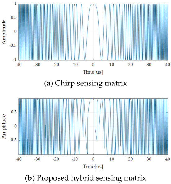
Figure 1.
LFM waveform comparison.
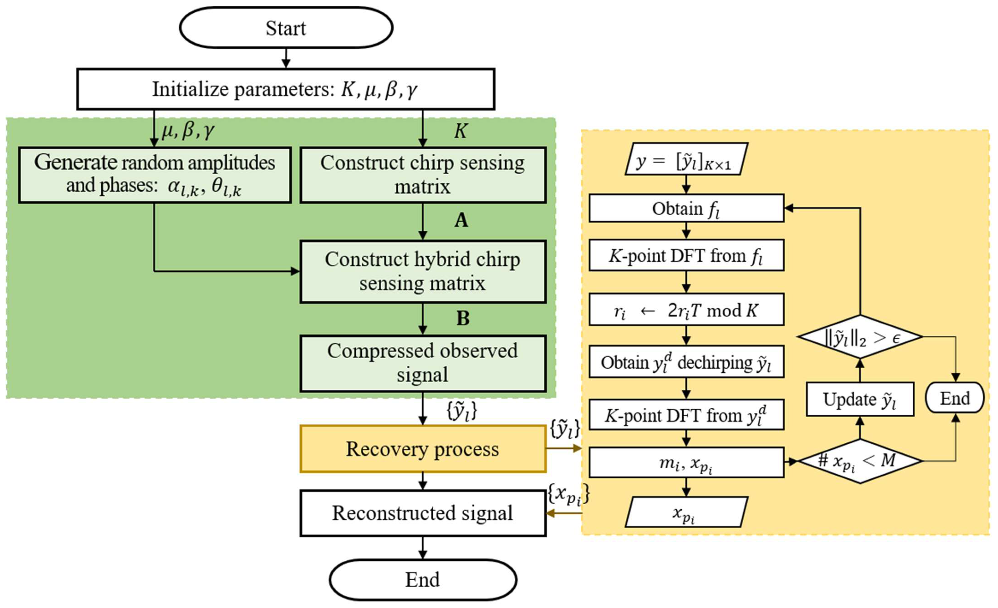
A hybrid CC-CS consists of a signal compression and recovery process, as shown in Figure 2. Initially, a chirp sensing matrix of size is generated. Then, it is multiplied element-wise with a stochastic matrix characterized by random amplitude and phase distributions. Afterward, the sparse signal is compressed and recovered using the generated hybrid chirp sensing matrix. Unlike the conventional CC-CS recovery process, is applied to the measured signal during the dechirping stage. Using , we obtain and take the K-point DFT of . Then, we find the location of the peak in the DFT represented as mod K and record the unique corresponding to the peak location. is computed by dechirping , and is obtained by taking the K-point DFT of . The recovery process is repeated until the energy of decreases below , where is the tolerance for termination defined by the minimum target energy in in the recovery process.
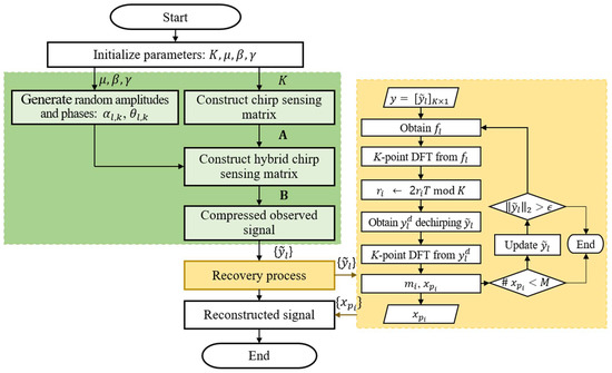
Figure 2.
Hybrid CC-CS processing block diagram.
Here, our goal is to maximize the autocorrelation part of relative to the cross term in (21); thus, the optimization problem can be formulated as follows:
In other words, we jointly design the parameters , , and to adjust the distributions for the amplitude and phase under the RIP condition. The search for the optimal set of parameters is not straightforward, as the recovery performance is not fully deterministic and is partially influenced by the statistical characteristics of the sensing vectors and the measured signals.
3.1. RIP Conditions
Using arguments analogous to the uniqueness analysis presented in [44], here we derive a bound on the sparsity order M for to hold for . Assume that and are scaled such that their column vectors have unit norms in both cases. For (15) to be satisfied, the following condition should be met [40]:
where is an arbitrary eigenvalue of . For a prime number K, the inner products between non-identical chirp codes satisfy , where is the th element of . Suppose that the number of sparse elements in the target signal is and is the corresponding hybrid sensing matrix. Let be an arbitrary eigenvalue of . By Gershgorin’s circle theorem [65], the following condition holds
where is the th element of , given by
Here, because the column of has unit norm, and . Hence, Gershgorin’s theorem in (24) can be rewritten as
From (26), the upper bound of for the hybrid sensing matrix is given by
where . Therefore, the maximum allowable number of sparse elements, M, satisfies
where .
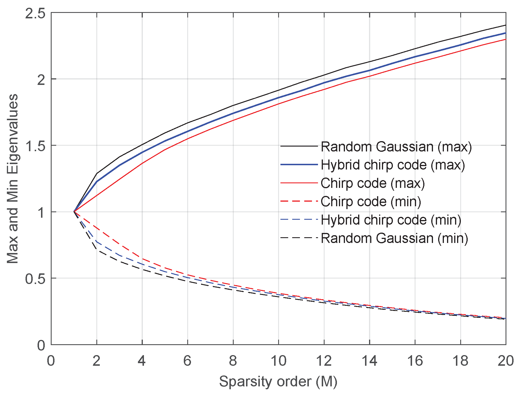
Figure 3 compares the maximum and minimum eigenvalues according to the sparsity order M for the random Gaussian sensing matrix, the chirp sensing matrix, and the proposed hybrid sensing matrix, when , , , and . For every value M, the columns of the sensing matrix was randomly selected and each point of the maximum and minimum eigenvalues was obtained by averaging over 1000 independent realizations. As shown in [40], the maximum eigenvalue corresponding to the chirp sensing matrix is smaller than that of the random Gaussian. As expected, the maximum eigenvalue of the proposed hybrid sensing matrix is between the chirp code and the random Gaussian. Thus, the number of sparse elements that can recover with high probability slightly decreases in the proposed hybrid sensing matrix compared to that of the chirp sensing matrix. However, the proposed hybrid sensing matrix has more degrees of freedom to adjust its elements, while the chirp sensing matrix is completely deterministic. This property helps improve the recovery performance of the proposed method. Note that the random Gaussian sensing matrix has the highest degrees of freedom.
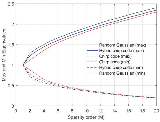
Figure 3.
Maximum and minimum eigenvalues according to the sparsity order M for various sensing matrices.
3.2. Hybrid CC-CS Reconstruction Performance
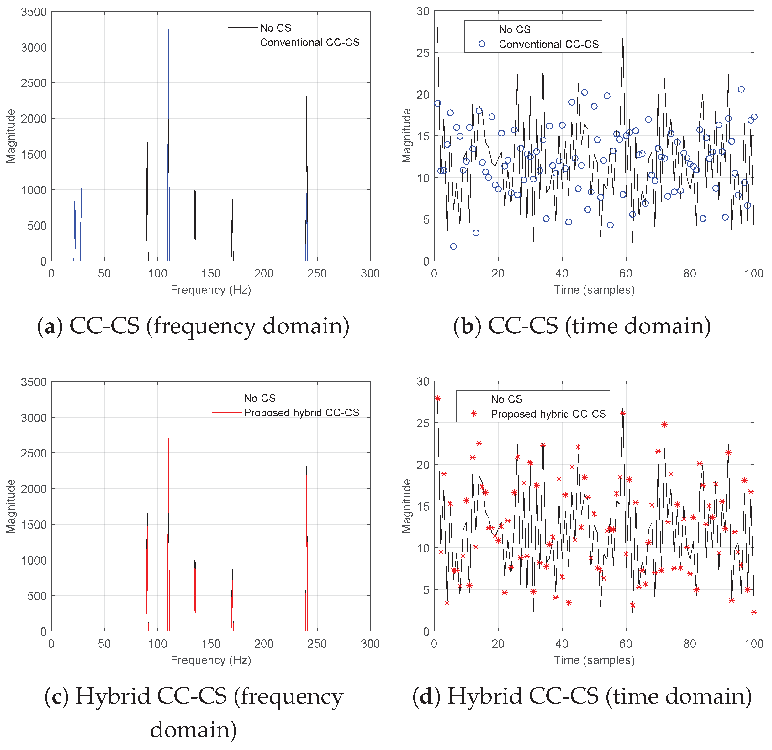
To evaluate the recovery performance of the proposed hybrid chirp sensing matrix, we carry out numerical simulations for simple targets and compare the results with the existing CC-CS method. It is assumed that a frequency-modulated continuous wave (FMCW) radar observes five targets at different ranges and the received signal is subsampled using a sensing matrix with . In this case, the matrix size is having the compression ratio of 17, i.e., the measurement ratio is . For the proposed method, we set the control parameters as , , and . It is essential to determine the random control parameters , , and for generating the random amplitudes and phases in (17). Due to the complicated structure of the proposed hybrid sensing matrix, it is difficult to find the optimal values in a closed form. Alternatively, the optimal values for the random control parameters are found by an exhaustive search. This procedure is further investigated in the SAR imaging examples in Section 4.3. The signal-to-noise ratio (SNR) is assumed to be sufficiently high. Figure 4 illustrates the recovery performances of the existing CC-CS and proposed hybrid methods in the time and frequency domains. The solid black lines represent the uncompressed target signals. The CC-CS scheme exhibits significant recovery errors in Figure 4a, whereas the proposed method successfully recovers the five targets in Figure 4b.
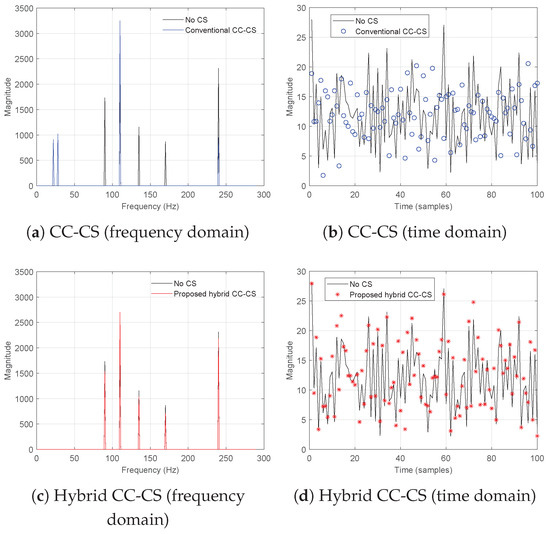
Figure 4.
Recovery performance comparison between the existing CC-CS and the proposed hybrid CC-CS (the black solid lines denote the original signals without CS).
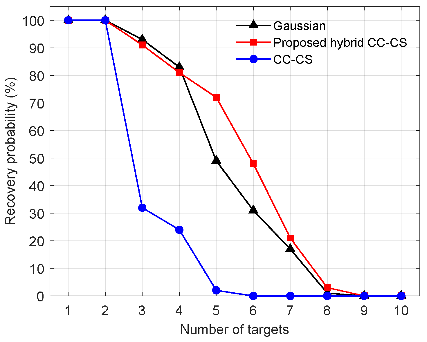
For further verification, Monte Carlo simulations are conducted to perform an extensive analysis of the recovery performance. Figure 5 represents the successful detection probability for varying number of targets, which are obtained by averaging the results over 1000 trials. For comparison, a conventional basis pursuit denoising (BPDN) method in [4] is employed using the random Gaussian sensing matrix. For K = 17, the RIP condition in (15) constrains the target recovery limit as 2 for CC-CS. As predicted, the CC-CS method its recovery performance is consistently below the theoretical limits due to its deterministic nature and shows a significant degradation in target recovery when the number of targets exceeds three, and presents a complete loss beyond 5. In contrast, the proposed hybrid CC-CS demonstrates a substantial improvement in recovery probability, comparable to that of the conventional random Gaussian sensing approach. The hybrid CC-CS algorithm introduces partial randomness, which impacts recovery performance. This random property becomes more pronounced when the vector size or the K constant is small. Specifically, the eigenvalues in Figure 3 were generated with , whereas was used in Figure 5. The smaller K likely increased the randomness of the recovery performance, particularly when the number of targets is small. Additionally, the choice of control parameters (, , ) plays a crucial role in determining recovery performance. In Figure 5, we can assert that the employed control parameters were optimized for the scenario, leading to superior recovery performance for target numbers 5 and 6. This optimization contributed to the observed improvement in recovery probability. Thus the optimization process for the control parameters is essential for the hybrid CC-CS and will be further analyzed in Section 4.3.

Figure 5.
Recovery probabilities for various sensing matrices according to the number of targets.
The advantage of the hybrid CC-CS method becomes particularly evident at higher compression ratios. Only 5.9% of the total received data are required to recover the targets shown in Figure 5, a level of compression that is difficult to achieve with the Gaussian sensing method. This high compression ratio effectively suppresses undesirable clutter noise in the output image and enhances the target recovery rate compared to the Gaussian sensing approach. In the next section, the performance evaluation is carried out for SAR imaging scenarios.
4. SAR Imaging Based on Proposed Sensing Matrix
4.1. SAR Imaging Using Undersampled Data
LFM waveforms are commonly used for the transmit signal in SAR operations. The overall received echo signal is acquired over the target area as follows:
where is the two-dimensional reflectivity from the target with a slant range R located over the target scene . When ignoring the propagation attenuation in the stripmap mode, the along-track time sample from a point target at R can be described as
where is the azimuth envelope; denote the slow and fast times; rect(x) represents the unit rectangular function, defined as rect(x) = 1 for and rect(x) = 0 otherwise; is the instantaneous time delay; is the center frequency; and is the chirp rate of the transmitted LFM signal. To reduce the volume of stored SAR measurement data, the proposed scheme applies compressive sensing to the azimuth data samples, achieving a decreased dimension by a factor of .
In the discrete domain, we assume that the received echo signal is constructed from the sparse target scene through the transfer function denoted as . For the sparse signal recovery, is measured via the sensing matrix as
In the context of conventional -norm solution, the column vector is recovered by solving the following problem:
where .
To construct the SAR imaging function, the conventional range-Doppler algorithm is employed and can be obtained through transform-domain processing of the received signal as
where and denote the partial DFT matrices in azimuth and range directions, is the interpolation operator for range cell migration correction (RCMC), and and are the frequency-domain matched filters in azimuth and range directions, respectively. Here, is the submatrix of the -point DFT matrix comprising the first rows and is the submatrix of the -point DFT matrix consisting of the first columns. Acceleration and angular velocity data are measured from the inertial measurement unit (IMU) onboard the SAR platform and loaded into the system for motion compensation. In (33), represents the phase compensation term used to correct residual motion errors. In (33), we denote the range-compressed signal in the frequency domain after RCMC and motion compensation as , as below:
Then, the reflectivity map of the target scene is represented as
where is the azimuth matched filter in the frequency-domain, given by
Here, is the Doppler frequencies varying along the azimuth direction and means the azimuth FM rate, where is the sensor velocity, is the range at the scene center, and c is the light velocity.
Let us define , and then in (35) can be rewritten as
When the hybrid sensing matrix is used for CS, the undersampled measurement of the received signal can be expressed as
By comparing (31) and (38), the sensing matrix can be denoted as follows:
The matrix is the time-domain convolution corresponding to the azimuth matched filtering in the frequency domain. In principle, is the multiplication of the hybrid matrix and , and . Since and have the same eigenvalues, the RIP condition in Section 3.1 is well preserved, ensuring the recovery performance of the sparse target scene from the undersampled measurement . To construct the sparse image from the compressed matrix , we initially utilize the conventional matched filtering for range compression and conduct the RCMC as shown in (34). Then, given the azimuth frequency-domain matrix , the recovery process is carried out by applying the sensing matrix derived in (39) to the CC-CS reconstruction procedure. The proposed recovery method, referred to as the hybrid CC-CS, is summarized as Algorithm 1.
| Algorithm 1: Proposed hybrid CC-CS for fast SAR imaging |
1: Input: , , K, , 3: For to M do 4: Construct the concatenated sensing matrix: . 5: Compute the compressed measurement matrix: . 6: Compute from using (20) and take the K-point DFT. 7: Find the peak location in the frequency spectrum as mod K. 8: Obtain by dechirping : . 9: Take the K-point DFT of . 10: Find the peak position to , recover the corresponding value . 11: Update : for . 12: If , go to step 14. 13: end for 14: Obtain using . 15: Output: |
To maximize the probability of sparse target detection with a minimum sub-sampling rate, it is crucial to increase the correlation between the sensing matrix and radar signals while maintaining a low RIC. The method proposed can be applied to all radar systems and SAR processing is a good candidate as its phase distributions exhibits chirp patterns. For demonstration, we conducted compressive sensing-based SAR simulations by employing the hybrid CC-CS in next section.
4.2. Modeling and Simulations for SAR Imaging
SAR imaging simulations are carried out to evaluate the performance of the proposed hybrid CC-CS and compare it with other CS-based imaging methods. Specifically, the following techniques are considered in the simulations.
- RDA (no CS): The standard RDA is applied to the received echo signal without CS.
- OMP [8]: A random Gaussian sensing matrix is used in combination with the orthogonal matching pursuit (OMP) in [8], which is a greedy-based method.
- BPDN [4]: A random Gaussian sensing matrix is used in combination with the BPDN in [4], the -norm convex optimization method.
It is assumed that an airborne SAR platform is employed to monitor multiple point targets on the ground and the radar parameters are shown in Table 1.

Table 1.
SAR simulation parameters.
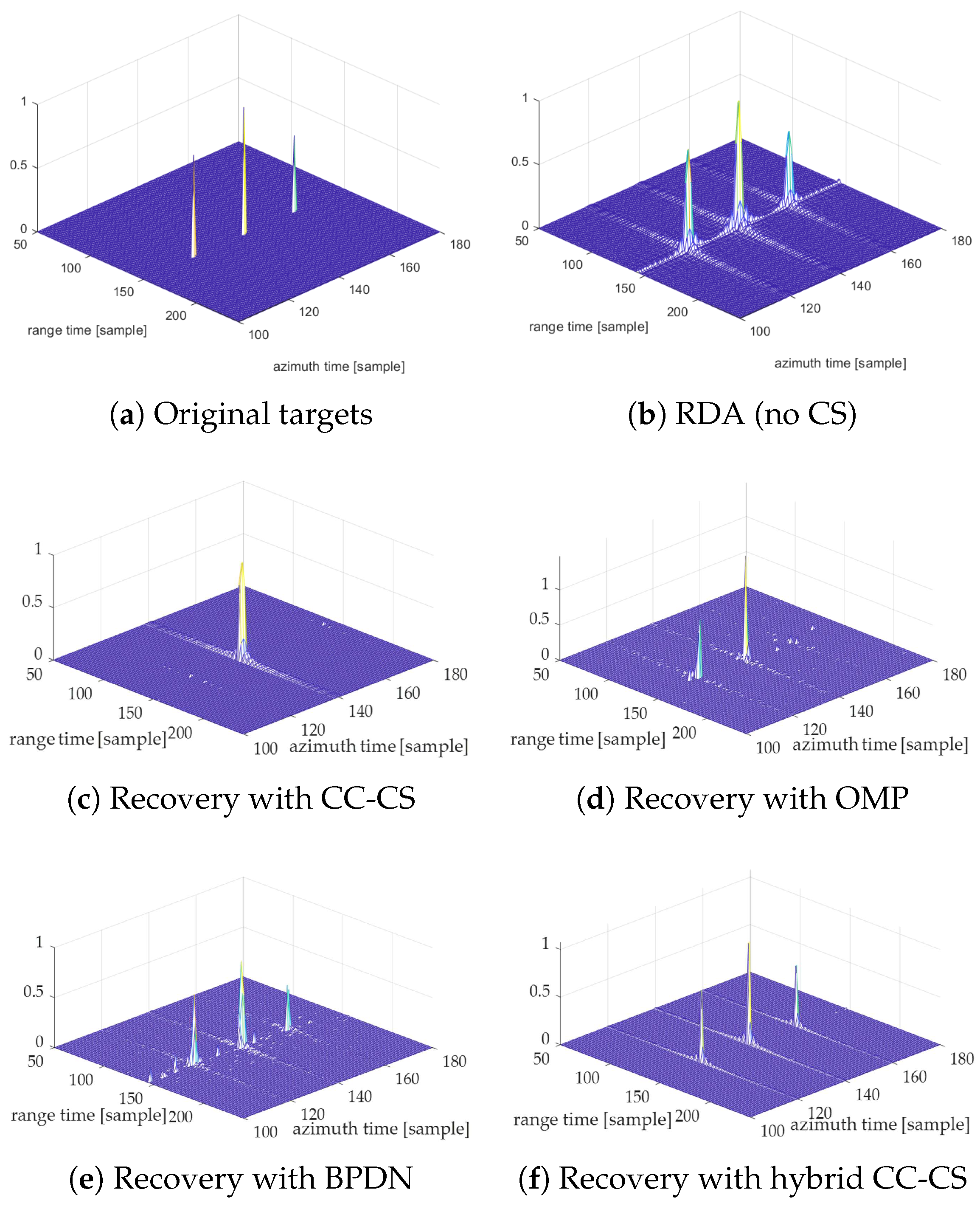
Figure 6a illustrates the reference image configuration of three point targets on the ground. Three point targets lie at the same range bin with one peak response at the center and the other smaller responses at different azimuth positions, where the target image size is (= ). We set for both CC-CS and hybrid CC-CS sensing matrix, so the measurement ratio is . As a baseline imaging technique, the standard RDA is applied to the received data with a sampling rate of 70 MHz (i.e., the oversampling rate is 1.17) and the pulse repetition frequency (PRF) of 150 Hz. Figure 6b presents the generated SAR image that corresponds to the reference target scene. In Figure 6c, the conventional CC-CS method recovers only one target and fails to recover the other two targets. This loss has been anticipated earlier when the maximum number of target recovery for CC-CS was severely limited, as demonstrated in (15), constraining the RIC and limiting the maximum number of recoverable targets to less than 2. In Figure 6d, the OMP scheme acquires sharp responses for two point targets and exhibits an incomplete recovery, with a loss of one target with relatively low reflectivity. This loss is attributed to the iterative subtraction process of the greedy algorithm. The BPDN method successfully recovers all three target responses in Figure 6e. However, it introduces increased clutter that may be conceived as false targets and could result in the loss of weak target responses. By contrast, the proposed hybrid CC-CS method achieves complete recovery of all targets, as shown in Figure 6f. Additionally, undesirable sidelobes and clutter are effectively suppressed, resulting in an enhanced target-to-clutter ratio.
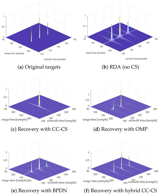
Figure 6.
Comparison of SAR image processing recovery performance (2D).
Table 2 compares the runtimes with respect to each processing method. All the CS-based methods inevitably suffer from increased execution times compared to the standard RDA case. Although the BPDN successfully recovered all targets, it demands a relatively high runtime due to the computational intensity of the -norm convex optimization algorithm. Note that the CS-based method utilizes only about 5.9% of the total data storage required by the RDA without CS. Overall, the proposed hybrid CC-CS offers significant advantages in terms of both image quality and computational complexity.
Table 2.
Runtime for SAR simulations when the measurement ratio is .
4.3. Control Parameter Optimization for SAR Signal Processing
To maximize the probability of sparse target detection with a minimum sub-sampling rate, it is crucial to increase the correlation between the sensing matrix and target signals while maintaining a low RIC. For this purpose, the proposed hybrid sensing matrix demands a design process of the random control parameters , , and optimized for the given scenario. In this regard, we conduct CS-based SAR simulations by employing an airborne SAR platform to monitor multiple point targets on the ground with the system parameters in Table 1. As a baseline imaging technique, the standard RDA is applied to the received data with a sampling rate of 70 MHz (i.e., the oversampling rate is 1.17) and a pulse repetition frequency (PRF) of 150 Hz. We set for the hybrid sensing matrix, resulting in a measurement ratio of . As shown in Figure 6a, three point targets lie at the same range bin with one peak response at the center and the other smaller responses at different azimuth positions, where the target image size is (= ). The performance of the proposed hybrid CC-CS is measured by the normalized mean square error (NMSE) between the target scene and the reconstructed SAR image , defined as
where means the Frobenius norm of .
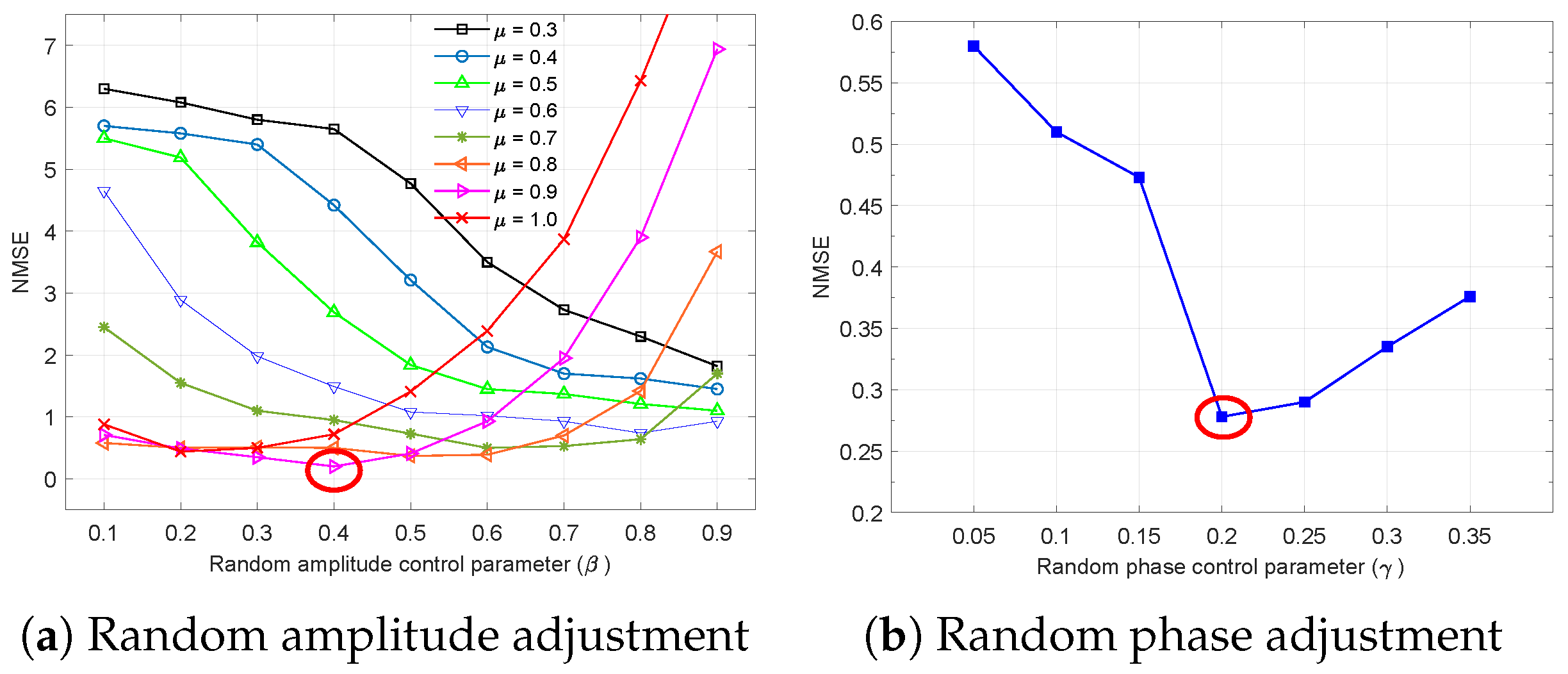
Through iterative simulations, a grid search was conducted to determine the optimal parameters, wherein the parameter was varied from 0.3 to 1.0 with a stepsize 0.1, was changed from 0.1 to 1.0 with a stepsize 0.1, and was varied from 0.05 to 0.35 with a step size of 0.05, respectively. The computational burden is excessive when the three parameters are adjusted simultaneously. To reduce the computational load, a sequential search strategy was adopted. Specifically, the parameter was initially set to 0, and an optimal pair (, ) was determined through a grid search. Subsequently, the optimal value of was found by fixing (, ) to the previously obtained optimal values. The grid search results are presented in Figure 7. In the simulations, the minimum NMSE was obtained when , , and . However, different parameter sets may yield optimal results in other scenarios. The optimal set of parameter values may depend on the target structure of the imaging areas and radar system, necessitating the adjustment of random properties. Hence, the sensing matrix is adaptively constructed through the choice of optimal control parameters, which are determined based on the size of the target scene and system parameters.
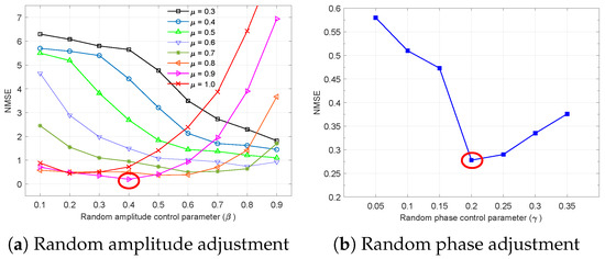
Figure 7.
Recovery performance according to random amplitude and phase control parameters , and .
5. Experimental SAR Imaging and Verification
Detecting targets in mountainous terrain is challenging due to clutter-like obstacles that hinder visibility. To cope with this, we developed a custom-built drone SAR platform for concealed target detection scenarios, as shown in Figure 8. The limited memory capacity and communication links of drone system restrict the operational range and duration. Processing the entire scene is inefficient, especially when buried targets are sparsely distributed. The proposed hybrid CC-CS algorithm is specifically designed for highly sparse target imaging, particularly in scenarios where clutter suppression is critical and data capacity is constrained. For experimental validation, an FMCW SAR system was implemented on a quadcopter drone. The system parameters are detailed in Table 3. The PRF was set to 25 Hz to reduce range ambiguity at low altitude and minimize power consumption given the limited battery capacity. However, this PRF is lower than the minimum Nyquist sampling rate in the azimuth direction and thus will result in aliasing effects in the image.
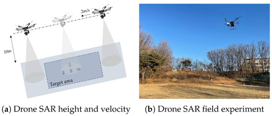
Figure 8.
Drone SAR experiment scenario.
Table 3.
SAR experimental parameters.
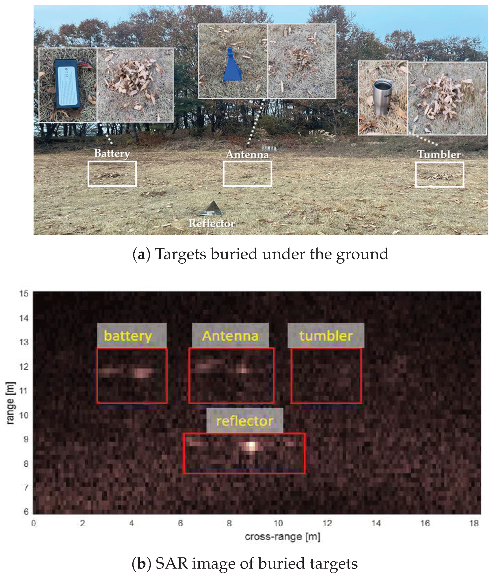
Figure 9a illustrates the operation site, where test targets, including a battery, antenna, and tumbler, are concealed beneath soil, foliage, and bushes, respectively. A standard reflector is positioned nearby as a reference target. In the test, the targets were buried under shallow soil and then further obscured with foliage. This setup was partly intended to specify the precise location of the targets for validation purposes.Due to the extremely low SNR and the absence of a strong point target, the motion compensation did not yield significant improvements in focusing performance. However, the resulting image highlights the strength of the proposed algorithm, which can recover sparse targets with high probability even under severe conditions such as low SNR and defocusing. The SAR image generated using conventional RDA processing is shown in Figure 9b. Unlike the reflector target, the concealed objects are difficult to distinguish from surrounding clutter. In particular, the tumbler appears barely visible due to its relatively low reflectivity. As expected, ghost images appear due to the aliasing effect in azimuth direction. To apply hybrid CC-CS processing, the image area should be divided into sub-blocks with appropriate dimensions. The image size of Figure 9 is . Multiple sub-block processing is implemented to rearrange the raw data to fit for the proposed processing such that the azimuth length is given by dimensions, where is a prime number and q is the number of sub-blocks.

Figure 9.
Real SAR imaging for the buried targets in the test site.
Figure 10 illustrates the procedure for applying the hybrid CC-CS algorithm to arbitrary SAR scene data. Following range processing and motion compensation, the image data are divided into sub-blocks along both the range and azimuth directions. The azimuth dimensions of the sub-blocks are divided into , , ⋯, , while the range dimensions are of arbitrary lengths. SNR is calculated for each sub-block to determine the threshold level for the recovery process. The control parameters may vary depending on the scenario, including the number of targets and vector size. In this experiment, we employed the same approach demonstrated in Figure 7 to determine the optimal parameters. The employed parameters are (,,) = (0.9,0.5,0.15) for the tumbler target and (,,) = (0.8,0.4,0.3) for the battery target. Finally, the hybrid CC-CS processing is applied in azimuth directions as described in Figure 10 and the complete image is restored.
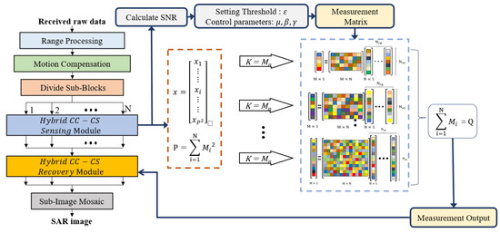
Figure 10.
SAR image processing block including the proposed hybrid sensing matrix.
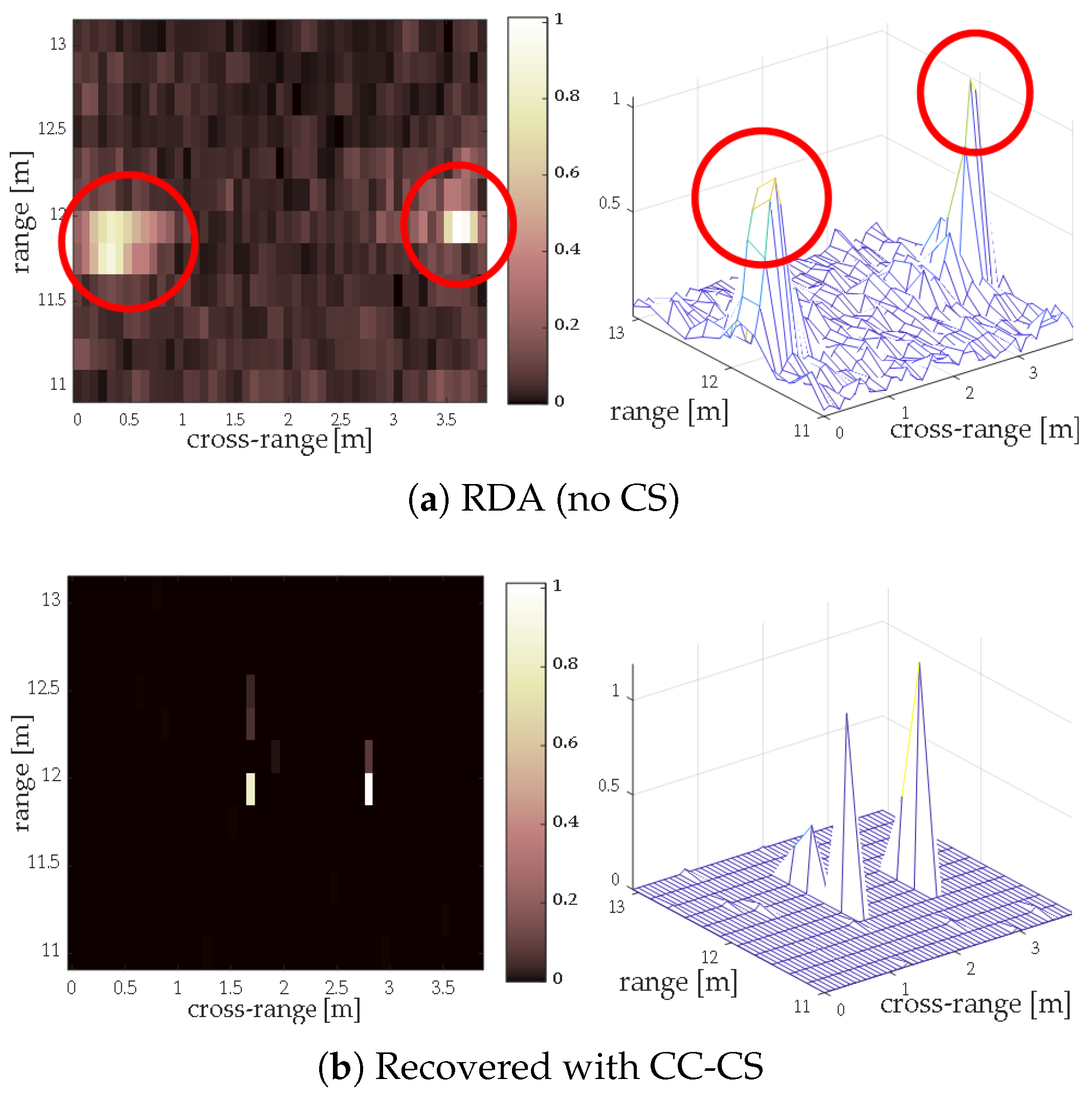
Figure 11 presents the processing results for the sub-block containing the tumbler target. The sub-imaging area spans 2 m in range and 4 m in azimuth, with a corresponding data size of . Figure 11a shows the image processed using the RDA, where the input data is lossless as raw data are streamed into the memory without sub-sampling. The CC-CS method generates two false targets in cluttered regions, failing to accurately reconstruct the true target map in Figure 11b. In contrast, the proposed hybrid CC-CS method in Figure 11e successfully reconstructs the true target map at the correct location, effectively suppressing surrounding clutter and enhancing image contrast. This reconstruction is achieved using only 14% of the total raw data with . At the same compression ratio, the OMP and BPDN failed to recover the target, as the generated images are disrupted by unwanted clutter, as shown in Figure 11c,d.
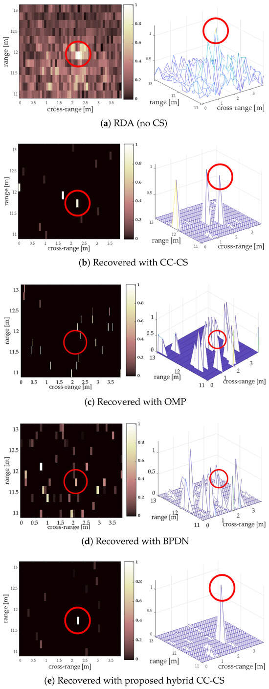
Figure 11.
Recovered SAR images for the tumbler (left: 2D, right: 3D).
A similar process is repeated for the sub-block containing the battery and antenna targets, and the resulting images are shown in Figure 12. As illustrated in Figure 12a, conventional SAR processing introduces high clutter noise that makes it difficult to distinguish the buried targets. Conventional CC-CS method generates targets at incorrect positions, possibly due to the restrictive RIP condition for the given compression ratio. Although OMP and BPDN methods recover the battery target, they both fail to detect the smaller antenna target, as presented in Figure 12c,d. In contrast, the hybrid CC-CS method successfully recovers all targets at their correct locations and effectively suppresses undesirable clutter energy, as shown in Figure 12e.
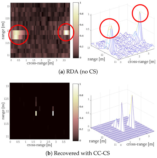
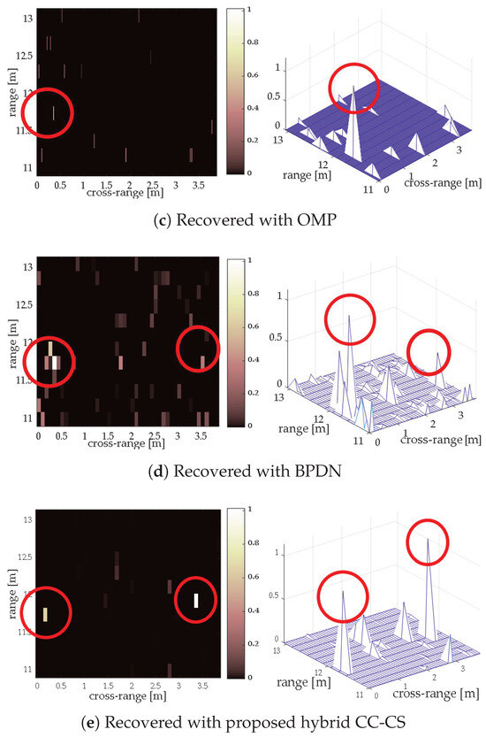
Figure 12.
Recovered SAR images for the antenna and battery targets (left: 2D, right: 3D).
Table 4 presents a comparison of the processing time for each method. RDA is performed using the full raw data, whereas only 14% of the received signal is utilized for other CS-based schemes. Of all the attempts, only the proposed hybrid CC-CS successfully recovers the buried targets while achieving high-speed processing comparable to the full RDA method. Thus, the superior precision and computational efficiency of the proposed algorithm is validated through the real SAR imaging experiment.
Table 4.
Simulation results for various algorithms.
It is noticeable that the drone radar system’s limited output power restricts the detectable soil depth above buried targets. To overcome this, we expect to develop a higher-power transmitter and adopt ultra-wideband signals to enable more comprehensive experiments over deeper underground sheltered targets, i.e., non-metal objects.
6. Conclusions
In this study, a hybrid deterministic sensing matrix was developed by integrating random control parameters for amplitude and phase perturbations to design a compressed recovery algorithm. We explored the feasibility of a hybrid approach for designing the CS sensing matrix, combining deterministic and random properties for enhanced recovery performance. We demonstrated the ability of the proposed algorithm to recover SAR data effectively in low-SNR scenarios, outperforming conventional CS algorithms. We also highlighted its significant improvement in compression ratio, achieving efficient recovery for a highly sparse target scene. The proposed method demonstrates significant improvements in data compression, processing speed, and noise resilience. Its application to SAR imaging is highly promising, particularly in scenarios when drone platforms are employed to search for a limited number of concealed targets over wide coverage areas.
For performance verification, SAR imaging experiments have been conducted using a small, lightweight drone platform to detect hidden targets. The experimental results present promising performances, detecting the obscured targets at high compression ratios. The proposed method is advantageous in terms of processing speed compared to conventional CS-based imaging schemes that utilize either random or deterministic sensing matrices.
Enhancing subsurface target detection would require increasing the system’s output power and bandwidth. To this end, we are currently working on implementing an upgraded system. We are also preparing additional experiments for various subsurface targets for future work. In future experiments, high-precision RTK-GPS will be utilized to enhance motion estimation accuracy. The enhanced performance has the potential to significantly benefit real-time search operations in future small SAR applications. The proposed algorithm can be easily implemented with the use of a software-defined radio receiver, enabling efficient sampling and real-time compressed sensing operation.
Author Contributions
H.-J.J. designed the conceptual algorithm and performed computer simulations; H.L. was in charge of the field measurement for obtaining the SAR raw data; W.L. provided guidance for this research; W.L. and J.C. wrote and revised the paper. All authors have read and agreed to the published version of the manuscript.
Funding
This work was supported by the Agency for Defense Development by Korean Government (UI5111J5-911256202).
Data Availability Statement
The raw data presented in this study are not publicly available due to the security policies of the funding institution.
Acknowledgments
The authors gratefully acknowledge the support from the Next-Generation SAR Research Laboratory at Korea Aerospace University, originally funded by the Defense Acquisition Program Administration (DAPA) and the Agency for Defense Development (ADD).
Conflicts of Interest
The authors declare no conflicts of interest.
References
- Donoho, D.L. Compressed sensing. IEEE Trans. Inf. Theory 2006, 52, 1289–1306. [Google Scholar] [CrossRef]
- Candes, E.J.; Romberg, J.; Tao, T. Robust uncertainty principles: Exact signal reconstruction from highly incomplete frequency information. IEEE Trans. Inf. Theory 2006, 52, 489–509. [Google Scholar] [CrossRef]
- Candes, E.J.; Tao, T. Near-Optimal Signal Recovery from Random Projections: Universal Encoding Strategies? IEEE Trans. Inf. Theory 2006, 52, 5406–5425. [Google Scholar] [CrossRef]
- Gill, P.R.; Wang, A.; Molnar, A. The In-Crowd Algorithm for Fast Basis Pursuit Denoising. IEEE Trans. Signal Process. 2011, 59, 4595–4605. [Google Scholar] [CrossRef]
- Donoho, D.L.; Maleki, A.; Montanari, A. Message passing algorithms for compressed sensing: I. motivation and construction. In Proceedings of the 2010 IEEE Information Theory Workshop on Information Theory (ITW), Cairo, Egypt, 6–8 January 2010; pp. 1–5. [Google Scholar] [CrossRef]
- Donoho, D.L.; Maleki, A.; Montanari, A. Message passing algorithms for compressed sensing: II. analysis and validation. In Proceedings of the 2010 IEEE Information Theory Workshop on Information Theory (ITW), Cairo, Egypt, 6–8 January 2010; pp. 1–5. [Google Scholar] [CrossRef]
- Tropp, J.A.; Gilbert, A.C. Signal Recovery from Random Measurements Via Orthogonal Matching Pursuit. IEEE Trans. Inf. Theory 2007, 53, 4655–4666. [Google Scholar] [CrossRef]
- Cai, T.T.; Wang, L. Orthogonal Matching Pursuit for Sparse Signal Recovery with Noise. IEEE Trans. Inf. Theory 2011, 57, 4680–4688. [Google Scholar] [CrossRef]
- Donoho, D.L.; Tsaig, Y.; Drori, I.; Starck, J. Sparse Solution of Underdetermined Systems of Linear Equations by Stagewise Orthogonal Matching Pursuit. IEEE Trans. Inf. Theory 2012, 58, 1094–1121. [Google Scholar] [CrossRef]
- Wang, J.; Kwon, S.; Li, P.; Shim, B. Recovery of Sparse Signals via Generalized Orthogonal Matching Pursuit: A New Analysis. IEEE Trans. Signal Process. 2016, 64, 1076–1089. [Google Scholar] [CrossRef]
- DeVore, R.A. Deterministic Constructions of Compressed Sensing Matrices. J. Complex. 2007, 23, 918–925. [Google Scholar] [CrossRef]
- Patel, V.M.; Easley, G.R.; Healy, D.M.; Chellappa, R. Compressed Synthetic Aperture Radar. IEEE J. Sel. Topics Signal Process. 2010, 4, 244–254. [Google Scholar] [CrossRef]
- Samadi, S.; Çetin, M.; Masnadi-Shirazi, M. Sparse representation-based synthetic aperture radar imaging. IET Radar Sonar Navig. 2011, 5, 182–193. [Google Scholar] [CrossRef]
- Aberman, K.; Eldar, Y.C. Sub-Nyquist SAR via Fourier Domain Range-Doppler Processing. IEEE Trans. Geosci. Remote Sens. 2017, 55, 6228–6244. [Google Scholar] [CrossRef]
- Yang, H.; Chen, C.; Chen, S.; Xi, F. Sub-Nyquist SAR via Quadrature Compressive Sampling with Independent Measurements. Remote Sens. 2019, 11, 472. [Google Scholar] [CrossRef]
- Yang, J.; Jin, T.; Huang, X. Compressed Sensing Radar Imaging with Magnitude Sparse Representation. IEEE Access 2019, 7, 29722–29733. [Google Scholar] [CrossRef]
- Song, S.; Dai, Y.; Jin, T.; Wang, X.; Hua, Y.; Zhou, X. An Effective Image Reconstruction Enhancement Method with Convolutional Reweighting for Near-Field SAR. IEEE Antenna Wirel. Propag. Lett. 2024, 23, 2486–2490. [Google Scholar] [CrossRef]
- Choi, J.; Lee, W. Drone SAR Image Compression Based on Block Adaptive Compressive Sensing. Remote Sens. 2021, 13, 3947. [Google Scholar] [CrossRef]
- Pournaghshband, R.; Modarres-Hashemi, M. A Novel Block Compressive Sensing Algorithm for SAR Image Formation. Signal Process. 2023, 210, 109053. [Google Scholar] [CrossRef]
- Wu, J.; Feng, D.; Wang, J.; Huang, X. SAR Imaging from Azimuth Missing Raw Data via Sparsity Adaptive StOMP. IEEE Geosci. Remote Sens. Lett. 2022, 19, 4501605. [Google Scholar] [CrossRef]
- Bi, H.; Feng, J.; Jin, S.; Yang, W.; Xu, W. Mixed-Norm Regularization-Based Polarimetric Holographic SAR 3-D Imaging. IEEE Geosci. Remote Sens. Lett. 2024, 21, 4002305. [Google Scholar] [CrossRef]
- Gilbert, A.; Indyk, P. Sparse Recovery Using Sparse Matrices. Proc. IEEE 2010, 98, 937–947. [Google Scholar] [CrossRef]
- Liu, X.J.; Xia, S.T.; Fu, F.W. Reconstruction Guarantee Analysis of Basis Pursuit for Binary Measurement Matrices in Compressed Sensing. IEEE Trans. Inf. Theory 2017, 63, 2922–2932. [Google Scholar] [CrossRef]
- Çetin, M.; Stojanović, I.; Önhon, N.O.; Varshney, K.; Samadi, S.; Karl, W.C.; Willsky, A.S. Sparsity-Driven Synthetic Aperture Radar Imaging: Reconstruction, autofocusing, moving targets, and compressed sensing. IEEE Signal Process. Mag. 2014, 31, 27–40. [Google Scholar] [CrossRef]
- Calderbank, R.; Howard, S.D.; Jafarpour, S. Construction of a Large Class of Deterministic Sensing Matrices That Satisfy a Statistical Isometry Property. IEEE J. Sel. Topics Signal Process. 2010, 4, 358–374. [Google Scholar] [CrossRef]
- Amini, A.; Marvasti, F. Deterministic Construction of Binary, Bipolar, and Ternary Compressed Sensing Matrices. IEEE Trans. Inf. Theory 2011, 57, 2360–2370. [Google Scholar] [CrossRef]
- Dimakis, A.G.; Smarandache, R.; Vontobel, P.O. LDPC Codes for Compressed Sensing. IEEE Trans. Inf. Theory 2012, 58, 3093–3114. [Google Scholar] [CrossRef]
- Li, S.; Gao, F.; Ge, G.; Zhang, S. Deterministic Construction of Compressed Sensing Matrices via Algebraic Curves. IEEE Trans. Inf. Theory 2012, 58, 5035–5041. [Google Scholar] [CrossRef]
- Mohades, M.M.; Kahaei, M.H. General Approach for Construction of Deterministic Compressive Sensing Matrices. IET Signal Process. 2019, 13, 321–329. [Google Scholar] [CrossRef]
- Wang, Y.; Qin, Y.; Ren, H. Deterministic Construction of Compressed Sensing Measurement Matrix with Arbitrary Sizes via QC-LDPC and Arithmetic Sequence Sets. Electronics 2023, 12, 2063. [Google Scholar] [CrossRef]
- Yu, N.Y.; Li, Y. Deterministic Construction of Fourier-Based Compressed Sensing Matrices Using an Almost Difference Set. EURASIP J. Adv. Signal Process. 2013, 2013, 155. [Google Scholar] [CrossRef]
- Xu, G.; Xu, Z. Compressed Sensing Matrices from Fourier Matrices. IEEE Trans. Inf. Theory 2015, 61, 469–478. [Google Scholar] [CrossRef]
- Hanumanthu, S.; Kumar P, R. Deterministic Compressed Sensing LFM Radar for Range-Doppler Estimation of Multiple Moving Targets. Measurement 2022, 187, 110315. [Google Scholar] [CrossRef]
- Wang, Z.; Jiang, Y.; Chen, S. Image Parallel Block Compressive Sensing Scheme Using DFT Measurement Matrix. Multimed. Tools Appl. 2023, 82, 21561–21583. [Google Scholar] [CrossRef]
- Li, S.; Ge, G. Deterministic Construction of Sparse Sensing Matrices via Finite Geometry. IEEE Trans. Signal Process. 2014, 62, 2850–2859. [Google Scholar] [CrossRef]
- Bryant, D.; Colbourn, C.J.; Horsley, D.; Ó Catháin, P. Compressed Sensing with Combinatorial Designs: Theory and Simulations. IEEE Trans. Inf. Theory 2017, 63, 4850–4859. [Google Scholar] [CrossRef]
- Lu, W.; Dai, T.; Xia, S.T. Binary Matrices for Compressed Sensing. IEEE Trans. Signal Process. 2018, 66, 77–85. [Google Scholar] [CrossRef]
- Lotfi, M.; Vidyasagar, M. A Fast Noniterative Algorithm for Compressive Sensing Using Binary Measurement Matrices. IEEE Trans. Signal Process. 2018, 66, 4079–4089. [Google Scholar] [CrossRef]
- Tong, F.; Li, L.; Peng, H.; Yang, Y. Deterministic Constructions of Compressed Sensing Matrices from Unitary Geometry. IEEE Trans. Inf. Theory 2021, 67, 5548–5561. [Google Scholar] [CrossRef]
- Applebaum, L.; Howard, S.D.; Searle, S.; Calderbank, R. Chirp Sensing Codes: Deterministic Compressed Sensing Measurements for Fast Recovery. Appl. Comput. Harmon. Anal. 2009, 26, 283–290. [Google Scholar] [CrossRef]
- Xu, Q.; Sheng, Z.; Fang, Y.; Zhang, L. Measurement Matrix Optimization for Compressed Sensing System with Constructed Dictionary via Takenaka–Malmquist Functions. Sensors 2021, 21, 1229. [Google Scholar] [CrossRef] [PubMed]
- Pllaha, T.; Tirkkonen, O.; Calderbank, R. Binary Subspace Chirps. IEEE Trans. Inf. Theory 2022, 68, 7735–7752. [Google Scholar] [CrossRef]
- Liu, J.; Mallick, M.; Lian, F.; Han, C.; Sheng, M.; Yao, X. General Similar Sensing Matrix Pursuit: An Efficient and Rigorous Reconstruction Algorithm to Cope with Deterministic Sensing Matrix with High Coherence. Signal Process. 2015, 114, 150–163. [Google Scholar] [CrossRef]
- Obermeier, R.; Martinez-Lorenzo, J.A. Sensing Matrix Design via Mutual Coherence Minimization for Electromagnetic Compressive Imaging Applications. IEEE Trans. Comput. Imag. 2017, 3, 217–229. [Google Scholar] [CrossRef]
- Gu, Z.; Zhou, Z.; Yang, Y.; Adhikary, A.R.; Cai, X. Deterministic Compressed Sensing Matrices from Sequences with Optimal Correlation. IEEE Access 2019, 7, 16704–16710. [Google Scholar] [CrossRef]
- Soumekh, M. SAR-ECCM Using Phase-Perturbed LFM Chirp Signals and DRFM Repeat Jammer Penalization. IEEE Trans. Aerosp. Electron. Syst. 2006, 42, 191–205. [Google Scholar] [CrossRef]
- Akhtar, J. Orthogonal Block Coded ECCM Schemes Against Repeat Radar Jammers. IEEE Trans. Aerosp. Electron. Syst. 2009, 45, 1218–1226. [Google Scholar] [CrossRef]
- Cheng, Y.; Zhang, J.; Li, C.; Zhu, D. Orthogonal Anti-Jamming Waveform Design with Extended Doppler Tolerance Based on the LFM-PC Signal. Digit. Signal Process. 2022, 122, 103334. [Google Scholar] [CrossRef]
- Schuerger, J.; Garmatyuk, D. Multifrequency OFDM SAR in Presence of Deception Jamming. EURASIP J. Adv. Signal Process. 2010, 2010, 451851. [Google Scholar] [CrossRef]
- Xu, J.; Liao, G.; Zhu, S.; So, H.C. Deceptive Jamming Suppression with Frequency Diverse MIMO Radar. Signal Process. 2015, 113, 9–17. [Google Scholar] [CrossRef]
- Yu, L.; Barbot, J.P.; Zheng, G.; Sun, H. Compressive Sensing with Chaotic Sequence. IEEE Signal Process. Lett. 2010, 17, 731–734. [Google Scholar] [CrossRef]
- Zhang, Y.; Dong, X.; Yang, Q.; Zhai, W.; Shi, X.; Yang, Q.; Kang, X. High-Resolution SAR/ISAR Imaging with Chaotic Noise Signals. In Proceedings of the 2017 IEEE Asia Pacific Microwave Conference (APMC), Kuala Lumpur, Malaysia, 13–16 November 2017; pp. 372–375. [Google Scholar] [CrossRef]
- Hong, S.; Zhou, F.; Dong, Y.; Zhao, Z.; Wang, Y.; Yan, M. Chaotic Phase-Coded Waveforms with Space-Time Complementary Coding for MIMO Radar Applications. IEEE Access 2018, 6, 42066–42083. [Google Scholar] [CrossRef]
- Pralon, L.; Beltrao, G.; Barreto, A.; Cosenza, B. On the Analysis of PM/FM Noise Radar Waveforms Considering Modulating Signals with Varied Stochastic Properties. Sensors 2021, 21, 1727. [Google Scholar] [CrossRef] [PubMed]
- Šipoš, D.; Gleich, D. A Lightweight and Low-Power UAV-Borne Ground Penetrating Radar Design for Landmine Detection. Sensors 2020, 20, 2234. [Google Scholar] [CrossRef]
- Noviello, C.; Esposito, G.; Catapano, I.; Soldovieri, F. Multilines Imaging Approach for Mini-UAV Radar Imaging System. IEEE Geosci. Remote Sens. Lett. 2022, 19, 3507105. [Google Scholar] [CrossRef]
- García-Fernández, M.; Álvarez Narciandi, G.; Álvarez López, Y.; Las-Heras Andrés, F. Improvements in GPR-SAR Imaging Focusing and Detection Capabilities of UAV-Mounted GPR Systems. ISPRS J. Photogramm. Remote Sens. 2022, 189, 128–142. [Google Scholar] [CrossRef]
- Grathwohl, A.; Stelzig, M.; Kanz, J.; Fenske, P.; Benedikter, A.; Knill, C.; Ullmann, I.; Hajnsek, I.; Moreira, A.; Krieger, G.; et al. Taking a Look Beneath the Surface: Multicopter UAV-Based Ground-Penetrating Imaging Radars. IEEE Microw. Mag. 2022, 23, 32–46. [Google Scholar] [CrossRef]
- Barnawi, A.; Kumar, K.; Kumar, N.; Thakur, N.; Alzahrani, B.; Almansour, A. Unmanned Ariel Vehicle (UAV) Path Planning for Area Segmentation in Intelligent Landmine Detection Systems. Sensors 2023, 23, 7264. [Google Scholar] [CrossRef] [PubMed]
- Garcia-Fernandez, M.; Alvarez-Lopez, Y.; Las Heras, F. Autonomous Airborne 3D SAR Imaging System for Subsurface Sensing: UWB-GPR on Board a UAV for Landmine and IED Detection. Remote Sens. 2019, 11, 2357. [Google Scholar] [CrossRef]
- Schartel, M.; Burr, R.; Schoeder, P.; Rossi, G.; Hügler, P.; Mayer, W.; Waldschmidt, C. Radar-Based Altitude over Ground Estimation of UAVs. In Proceedings of the 2018 11th German Microwave Conference (GeMiC), Freiburg, Germany, 12–14 March 2018; pp. 103–106. [Google Scholar] [CrossRef]
- Başpınar, O.O.; Omuz, B.; Öncü, A. Detection of the Altitude and On-the-Ground Objects Using 77-GHz FMCW Radar Onboard Small Drones. Drones 2023, 7, 86. [Google Scholar] [CrossRef]
- García-Fernández, M.; Álvarez Narciandi, G.; Álvarez López, Y.; Las-Heras, F. Array-Based Ground Penetrating Synthetic Aperture Radar on Board an Unmanned Aerial Vehicle for Enhanced Buried Threats Detection. IEEE Trans. Geosci. Remote Sens. 2023, 61, 5104218. [Google Scholar] [CrossRef]
- García-Fernández, M.; Álvarez Narciandi, G.; Laviada, J.; Álvarez López, Y.; Las-Heras, F. Towards Real-Time Processing for UAV-Mounted GPR-SAR Imaging Systems. ISPRS J. Photogramm. Remote Sens. 2024, 212, 1–12. [Google Scholar] [CrossRef]
- Li, C.K.; Zhang, F. Eigenvalue Continuity and Gersgorin’s Theorem. Electron. J. Linear Algebra 2019, 35, 619–625. [Google Scholar] [CrossRef]


Disclaimer/Publisher’s Note: The statements, opinions and data contained in all publications are solely those of the individual author(s) and contributor(s) and not of MDPI and/or the editor(s). MDPI and/or the editor(s) disclaim responsibility for any injury to people or property resulting from any ideas, methods, instructions or products referred to in the content. |
© 2025 by the authors. Licensee MDPI, Basel, Switzerland. This article is an open access article distributed under the terms and conditions of the Creative Commons Attribution (CC BY) license (https://creativecommons.org/licenses/by/4.0/).