Article

A Spoofing Detection and Direction-Finding Approach for Global Navigation Satellite System Signals Using Off-the-Shelf Anti-Jamming Antennas

1
School of Electronic Engineering, Xidian University, Xi’an 710071, China
2
National Key Laboratory of Electromagnetic Environment, Qingdao 266107, China
3
China Research Institute of Radiowave Propagation, Qingdao 266107, China
4
School of Geodesy and Geomatics, Wuhan University, Wuhan 430072, China
*
Author to whom correspondence should be addressed.
Remote Sens. 2025, 17(5), 864; https://doi.org/10.3390/rs17050864
Submission received: 20 January 2025 / Revised: 17 February 2025 / Accepted: 20 February 2025 / Published: 28 February 2025

Abstract

:
Global Navigation Satellite System (GNSS) spoofing induces the target receiver to obtain the wrong positioning and timing results, which is very harmful. It is necessary to develop high-precision GNSS spoofing detection and associated direction-finding methods. In order to achieve sensitive and high-precision direction-finding for GNSS spoofing, it is necessary to realize the spoofing signal detection in the capture phase. This paper first proposes a method of GNSS spoofing detection, based on machine learning, that extracts features in the capture phase, which realizes various types of spoofing detection such as matching power, carrier phase alignment, and frequency locking. Notably, existing spoofing-direction-finding methods are mainly based on dedicated antenna arrays, which incur high costs and are not conducive to large-scale deployments. The basis of the spoofing detection proposed by this paper consists of a differential phase-center correction method, which is proposed in the context of an off-the-shelf anti-jamming array antenna, which effectively reduces the impact of the phase-center jitter introduced by the mutual coupling between antenna arrays on the direction-finding. The publicly accessible Texas Spoofing Test Battery (TEXBAT) dataset and actual measured data are both used for test verification. The results demonstrate that the proposed spoofing detection method can achieve success rates of over 97% on the TEXBAT dataset and more than 96% on the measured dataset, and the accuracy of the proposed direction-finding method can reach 1°, which can realize the effective detection and direction-finding of GNSS spoofing.

1. Introduction

GNSS has been widely applied in fields such as transportation, electricity, and finance. However, GNSS signals are weak, and the format of its civilian signals is open, making them extremely vulnerable to various forms of electromagnetic interference, including jamming and spoofing.
GNSS security has garnered increasing attention in recent years. Unlike jamming, spoofing employs techniques such as pseudo-range scanning, synchronous regeneration, and signal forwarding to generate and broadcast signals that closely mimic those of GNSS signals. Spoofing requires less transmission power and is more difficult to detect. It can cause the target receiver to produce inaccurate positioning and timing data, potentially leading to significant safety risks in aviation and maritime contexts, as well as other security-critical sectors. In 2012, ‘a group of researchers from the University of Texas successfully controlled a drone at the White Sands Missile Range in New Mexico, U.S.A., using a spoofing test platform made of computers, external reference clocks, spoofing devices, and transmitting antennas [1]. In 2013, Todd led a spoofing test on the White Rose yacht, installing a Global Positioning System (GPS) spoofing device on the deck, which caused the yacht to deviate from its planned route [2]. In 2017, at least 20 ships near the Black Sea commercial port of Novorossiysk reported anomalies in GPS signals. Although the ships were at sea, their Automatic Identification System (AIS) tracks indicated they were on land, about 32 km inland [3]. Given the growing frequency and severity of spoofing attacks, it is crucial to develop high-precision spoofing detection and direction-finding technologies.
T. Pany et al. [4] and J. Dampf et al. [5] proposed spoofing detection and direction-finding methods based on the synthetic aperture of a moving antenna. However, these methods require antenna movement to achieve direction-finding for the spoofing interference and necessitate additional equipment, such as a turntable, making them costly and not suitable for widespread application. Pengrui Mao et al. [6] proposed a spoofing detection and direction-finding method using low-cost commercial GNSS receivers, which addresses issues such as antenna phase-center instability and inconsistent sampling times among multiple receivers. The direction-finding accuracy of this method can reach 5 degrees. Although low-cost, this method requires complete spoofing of the commercial receivers to enable direction-finding of spoofing, and its sensitivity and accuracy are limited. Huiyun Yang et al. [7] proposed a technique combining long- and short-baseline direction-finding of spoofing which can detect and locate spoofing sources which are weaker than normal satellite navigation signals. However, this method requires the use of a large, dedicated antenna. This paper introduces a novel spoofing detection and direction-finding method using an off-the-shelf anti-jamming array antenna.
To detect spoofing using the off-the-shelf anti-jamming antenna, the spoofing signal must first be separated from the real signal. Current spoofing detection methods include signal characterization [8,9,10,11,12], airspace analysis [13,14,15,16], external information-assisted detection [17,18,19], navigation information authentication [20,21], and machine learning detection [22,23,24]. Machine learning-based spoofing detection methods can reduce dependence on human intervention, adapt to new attack patterns, and achieve high accuracy with low false alarm rates. Among them, References [22,23] used the same seven feature parameters based on Radio Frequency (RF) and tracking phases. Reference [22] employed a spoofing detection model that used a Variational Autoencoder (VAE) and a Generative Adversarial Network (GAN), while Reference [23] utilized a two-stage artificial neural network model. Reference [24] used a Support Vector Machine (SVM) machine learning model with nine feature covariates in the tracking and positioning phases. These methods detect GNSS spoofing by integrating features from the RF capture, tracking, and positioning phases. However, to enable direction-finding and localization of the spoofing sources, it is essential to detect spoofing interference during the capture phase. This allows real signals and spoofed signals to be processed separately during the tracking phase and subsequent phases.
This paper presents a novel GNSS spoofing detection technique based on the LightGBM machine learning method and utilizing 13 features accessible during the receiver’s capture phase. This method can detect spoofing without relying on the tracking and positioning phases. The proposed feature set includes the receiver’s motion state, the number of captured correlation peaks, the average noise level, the captured reference value, the maximum correlation peaks, and ±9 correlation peak sampling values within a single code slice. These features account for factors such as the receiver’s motion state, multiple peaks caused by large delay spoofing, peak distortion from small delay spoofing, and noise increases due to spoofing. The LightGBM method, which supports efficient parallel training, is chosen in this paper. The model is trained using the publicly available TEXBAT dataset to prepare the 13 features for detection. Validation with the TEXBAT test dataset and real-world measured data demonstrates a detection accuracy of up to 97%, offering a highly efficient solution for spoofing detection during the capture phase.
After detecting the presence of spoofing signals among the real signals, a spoofing-direction-finding method can be employed; this paper presents a method, based on the differential phase-center correction technique, for off-the-shelf anti-jamming array antennas. Since the array elements in such antennas typically use conventional microstrip or helical designs, phase-center deviations can be significant, adversely impacting the accuracy of spoofing direction measurements. The proposed differential phase-center correction method effectively addresses both average and instantaneous phase-center deviations, reducing the errors caused by mutual coupling between antenna elements. Real-world tests demonstrate that this approach achieves a spoofing-direction-finding accuracy of up to 1 degree, enabling precise localization of spoofing sources.
The structure of this paper is organized as follows: Section 2 introduces the detection and direction-finding framework, Section 3 outlines the methods and underlying principles, Section 4 presents the experiments and results, Section 5 discusses the proposed method in detail, and Section 6 concludes the paper.

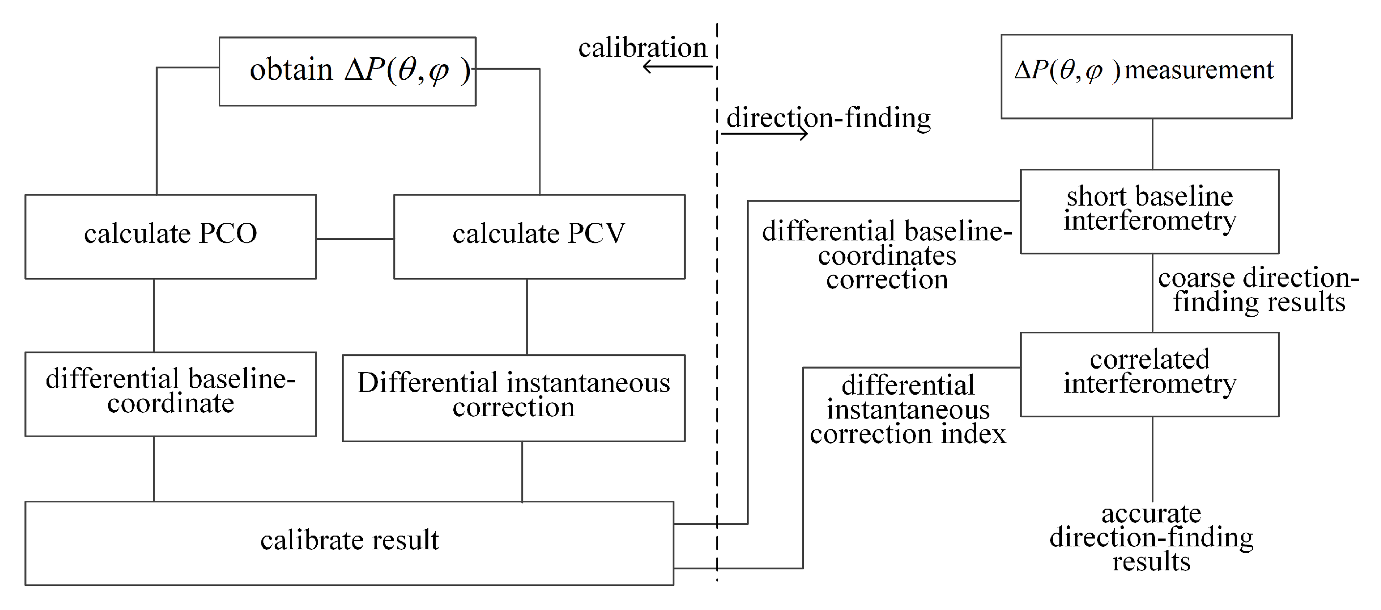
2. Detection and Direction-Finding Framework

Figure 1 illustrates the system architecture presented in this paper, which leverages off-the-shelf anti-jamming array antennas to achieve GNSS spoofing detection and direction-finding. The anti-jamming array antennas receive both real GNSS and spoofing signals. The RF module processes the received navigation signals and outputs intermediate frequency (IF) data. The capture module scans for frequency and code phase to identify and lock onto GNSS signals. The spoofing detection module detects spoofing by analyzing the characteristics of the captured signals. The tracking modules for both spoofing and real GNSS signals ensure continuous and precise synchronization of the spoofing signals and the authentic signals. The spoofing-direction-finding module determines the direction of the spoofing signal and outputs the corresponding results. Finally, the real position calculation module computes the actual position and provides the monitoring station’s real-time location, enabling the localization of the spoofing source.
The RF module, capture module, real signal tracking module, spoofing tracking module, and real position module all utilize mature methods. As shown in Figure 2, the spoofing detection module employs a LightGBM-based detection approach, utilizing 13 features derived from the capture stage, as proposed in this paper. Additionally, the spoofing-direction-finding module utilizes a direction-finding method based on differential phase-center correction, which is also proposed in this paper.

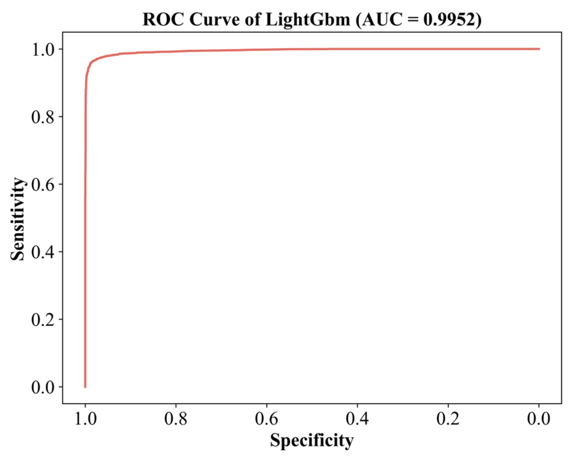
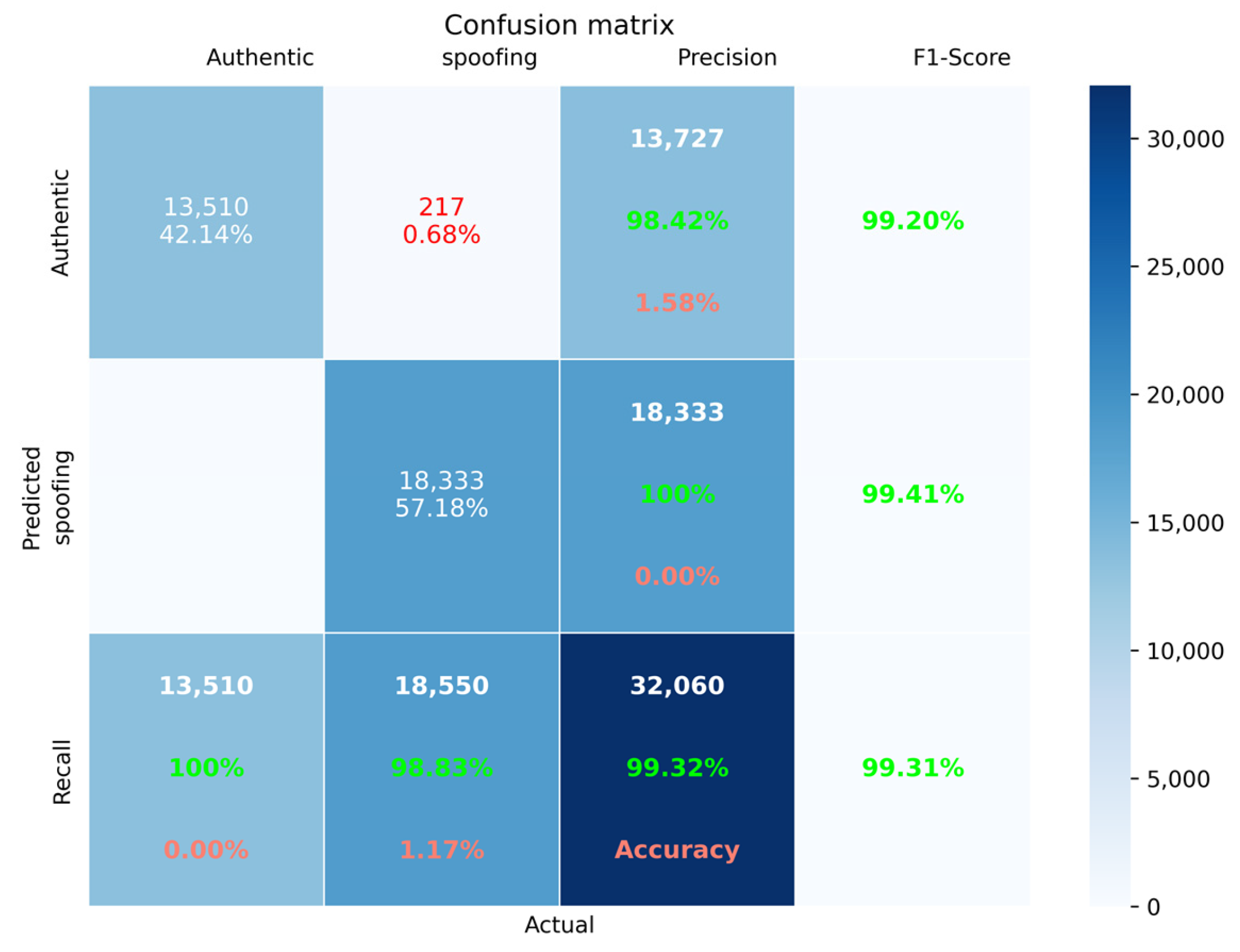
3. Spoofing Detection Method Based on LightGBM

3.1. Capturing Phase Signal Model

In a spoofing environment, the signals received by a GNSS receiver consist of real signals, spoofing signals, and noise. The signal model is expressed as follows:
s ( t ) = s T ( t ) + s S ( t ) + n ( t ) = i = 1 N P i T ( t ) C i ( t τ i T ) × D i ( t τ i T ) cos ( 2 π ( f i T + Δ f i T ) t + θ i T ) + k = 1 m P k S ( t ) C k ( t τ k S ) × D k ( t τ k S ) cos ( 2 π ( f k S + Δ f k S ) t + θ k S ) + n ( t )
where s T ( t ) is the real GNSS signal, s S ( t ) is the spoofing signal, n ( t ) is the additive Gaussian white noise, N is the number of visible satellites, i is the index for the i-th satellite, P i T ( t ) is the real GNSS signal power of the i-th satellite, τ i T is the propagation delay of the i-th satellite signal, C i ( t τ i T ) is the pseudo code sequence of the i-th satellite signal, τ i T is the propagation delay of the i-th satellite signal, D i ( t τ i T ) is the data code information modulated by the i-th satellite signal, f i T is the intermediate frequency of the i-th satellite signal, Δ f i T is the Doppler frequency shift of the i-th satellite signal, θ i T is the initial carrier phase of the i-th satellite signal, m is the number of spoofing signals, P k S ( t ) is the signal power of the k-th spoofing signal, C k ( t τ k S ) is the pseudo code sequence of the k-th spoofing signal, τ k S is the propagation delay of the k-th spoofing signal, D k ( t τ k S ) is the data code information modulated by the k-th spoofing signal, f k S is the intermediate frequency of the k-th spoofing signal, Δ f k S is the Doppler frequency shift of the k-th spoofing signal, and θ k S is the initial carrier phase of the k-th spoofing signal.
The coherent integrator output during the capture phase is influenced by the Doppler frequency of the local carrier and the code phase of the local C/A code. The integrator output for the i-th satellite channel is expressed as
y i ( τ i l , f i l ) = T c o h s ( t ) l i ( t , τ i l , f i l ) d t = P i T T c o h sin c ( π Δ f i T T c o h ) exp { j ( π Δ f i T T c o h + Δ θ i T ) } R ( τ i l τ i T ) + P i s T c o h sin c ( π Δ f i s T c o h ) exp { j ( π Δ f i S T c o h + Δ θ i s ) } R ( τ i l τ i s ) + n ( τ i l , f i l )
where Δ f i T and Δ θ i T are the frequency difference and phase difference between the real signal of the i-th satellite and the local carrier, respectively; Δ f i S and Δ θ i S denote the frequency difference and phase difference between the spoofing signal corresponding to the i-th satellite and the local carrier. T c o h is the coherent integration time; and R ( τ ) is the normalized autocorrelation function of the C/A code, expressed as
R ( τ ) = 1 τ , τ < 1   0 , other
n ( τ i l , f i l ) represents the correlated noise, which consists of the coherent integration results of noise, real signals from other satellites, spoofing signals, and locally generated signals. It can be expressed as
n ( τ i l , f i l ) = T c o h n ( t ) l i ( t , τ i l , f i l ) d t + j i T c o h s j T ( t ) l i ( t , τ i l , f i l ) d t + j i T c o h s j S ( t ) l i ( t , τ i l , f i l ) d t
where s j T ( t ) and s j S ( t ) represent the real signal and the spoofing signal of the j-th satellite, respectively.

3.2. Feature Extraction

We propose a GNSS spoofing detection method based on 13 features extracted during the capture phase. Details of the extraction methodology are provided below.

3.2.1. Receiver Status

The receiver’s status, whether stationary or moving, influences the frequency domain search during the acquisition phase. Therefore, the receiver’s state is used as one of the features, and referred to as “status”.

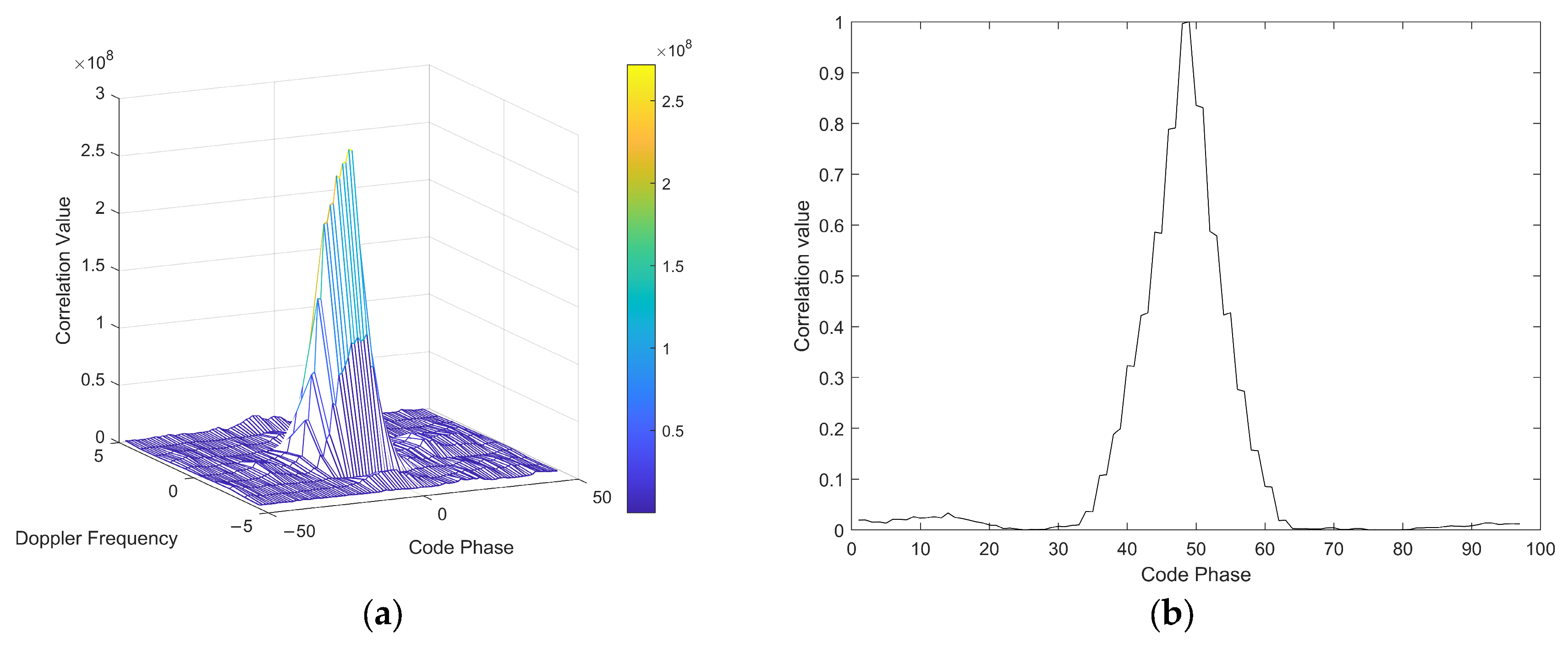
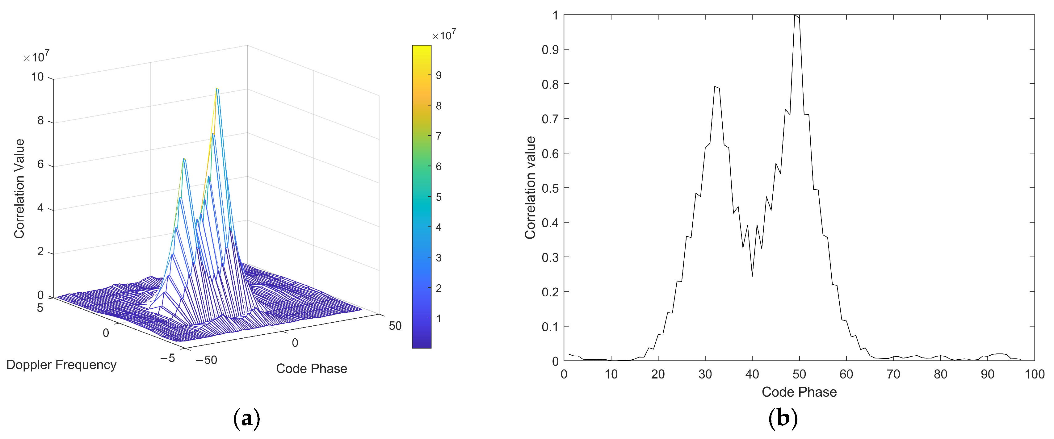
3.2.2. Number of Correlation Peaks

In the absence of spoofing, the receiver’s capture result, as shown in Figure 3, exhibits only a single correlation peak.
In a spoofing scenario, when the time delay of the spoofing signal τ s differs from the time delay of the real signal τ a by more than 1 chip, a double-peak phenomenon occurs during the capture phase. Figure 4 illustrates the capture result when the time delay difference between the spoofing and real signal is 1.1 chips.
Hence, the number of correlation peaks is selected as one of the features and denoted by “CPN”.

3.2.3. Mean Noise

As seen in Equation (4), spoofing affects the receiver’s noise characteristics. Therefore, the mean noise value over a period of time is selected as one of the features and denoted by “NP”.

3.2.4. Capture Parameter

To determine whether a satellite has been captured, we assess whether the capture parameter exceeds a certain threshold. One type of capture parameter can be expressed as
a c q P e a k M e t r i c = M a x C o r P e a k M e a n C o r S t d C o r
where M a x C o r P e a k is the maximum value of the correlation peak, M ean C o r is the mean of all correlation peaks outside the maximum value within one chip, and Std C o r is the standard deviation of all correlation peaks within one chip around the maximum value. In the presence of spoofing interference, this phenomenon affects both the maximum value of the correlation peak and the noise, thereby impacting the capture parameters. This value is taken as a feature and denoted by “CPM”.

3.2.5. Nine Correlation Peak Sampling Points Within ±1 Chip of the Maximum Correlation Peak Value

When τ s τ T 1 c h i p s , although there is no double peak phenomenon, the captured correlation peaks are distorted due to the superposition of the spoofing. Figure 5 shows the captured correlation peaks with a 0.5 chip delay difference between the spoofing signal and the real GNSS signal. It can be observed that when there is spoofing, the correlation peak will be distorted.
In order to realize the spoofing detection of τ s τ T 1 chips , nine correlation peaks with chip differences of −1, −0.75, −5, −0.25, 0, 0.25, 0.5, 0.75, and 1 from the maximum correlation peak are selected as nine features. These are denoted by CPV1, CPV2, CPV3, CPV4, CPV5, CPV6, CPV7, CPV8, and CPV9.

3.3. Machine Learning Classifier and Model Training

LightGBM (Light Gradient Boosting Machine) is a framework for implementing the GBDT (Gradient Boosting Decision Tree) algorithm. It supports efficient parallel training and offers advantages such as faster training speed, lower memory consumption, and better accuracy. In this paper, we use the LightGBM method for spoofing detection.
The publicly available dataset TEXBAT [25] was chosen to create the feature dataset for the model. This dataset is widely recognized as an authoritative GNSS spoofing dataset and provides a critical foundation for spoofing detection research. TEXBAT is provided by the Radio Navigation Laboratory (RNL) at the University of Texas at Austin and covers various spoofing scenarios on the civil GPS L1 C/A signal. The dataset is centered around a carrier frequency of 1575.42 MHz, with a bandwidth of 20 MHz, a sampling rate of 25 Msps, and 16-bit data storage. Table 1 below presents the TEXBAT data and descriptions used for the model training in this paper.
The TEXBAT data were processed using a MATLAB 2023 MATLAB 2023 version software receiver to generate the datasets. Each TEXBAT dataset lasts approximately 420 s, and a set of feature values was computed every 0.5 s for all visible satellites. Within the time duration in which spoofing was imposed and sustained, the labels for real GNSS signals and spoofing signals were assigned as follows: real signals were labeled as 1, and spoofing signals were labeled as 2. The distribution of real GNSS and spoofing signals in the constructed dataset is shown in Figure 6.
The resulting dataset was randomly divided, with 70% being allocated to the training set and 30% to the test set. The optimization parameters for LightGBM were determined via grid search. The correlations of the selected feature values are shown in Figure 7. The ellipses and colors visually represent the correlations between different features: the orientation of the ellipses indicates the direction of correlation (‘/’ for positive, ‘\’ for negative, and circular for no correlation), the size of the ellipses represents the strength of correlation (larger for stronger, smaller for weaker). As seen in the figure, the selected features are reasonable and exhibit low redundancy.
The Receiver Operating Characteristic Curve (ROC) and Area Under the Curve (AUC) values obtained are shown in Figure 8; AUC = 0.9952.
We applied several kinds of classification assessment criteria to evaluate the performance of the classifiers, including accuracy, precision, recall, and F1-measure. The formulae associated with these criteria are presented in Equations (6)–(9), in which TP is the true positive, TN is the true negative, FN is the false negative, and FP is the false positive.
The confusion matrices for the training and test sets were obtained by calculation and are shown in Figure 9 and Figure 10, respectively. For the test set, the recognition accuracy is 99.32%, while for the training set, the recognition accuracy is 97.15%. The TEXBAT dataset includes various types of spoofing, such as a spoofing signal with higher power than the real signal, carrier phase alignment, frequency locking, etc. The spoofing detection algorithm proposed in this paper effectively distinguishes between spoofing and real GNSS signals.
A c c u r a c y = T P + T N T P + T N + F P + F N
Precision = T P T P + F P
Recall = T P T P + F N
F 1 = 2 Pr e c i s i o n Re c a l l Pr e c i s i o n + Re c a l l
Reference [24] proposed a spoofing detection method based on SVM machine learning and utilizing TEXBAT data for both training and validation. The extracted features include nine based on the tracking phase and the solution phase: signal quality metric (SQM), SQM moving mean, SQM moving variance, C/N0 moving variance, pseudo-range Doppler, positioning residuals, velocity residuals, receiver clock offset, and receiver clock offset rate. A comparison of the spoofing detection results for the method proposed in this paper with the results for the method described in Reference [24] is shown in Table 2.

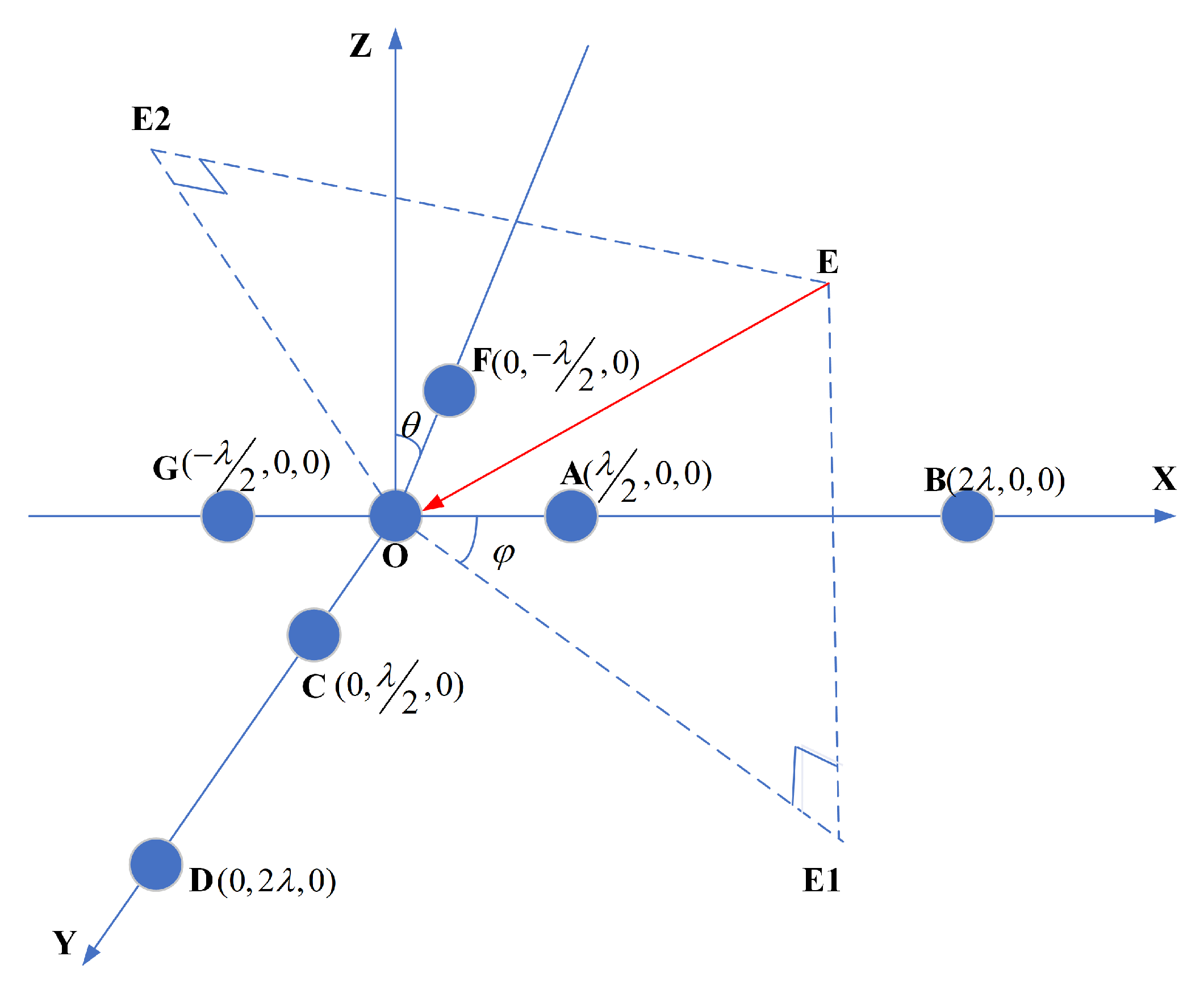
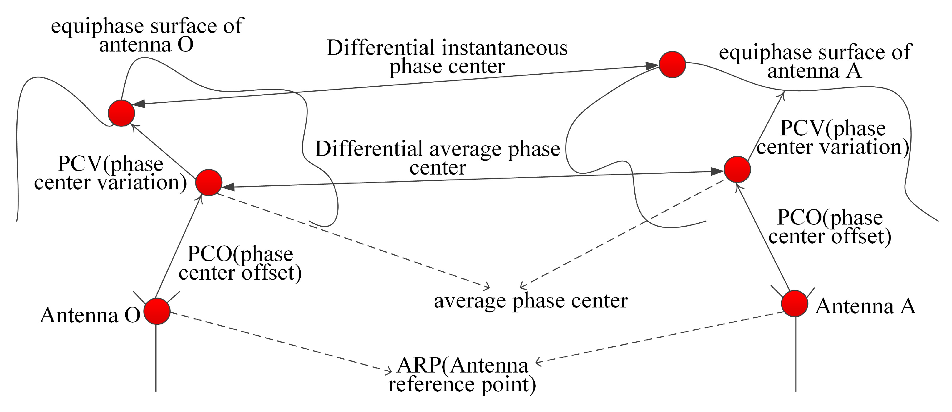
4. Spoofing-Direction-Finding Method Based on Differential Phase-Center Correction

4.1. Analysis of Spoofing-Direction-Finding Errors

Once the real and spoofing signals are identified during the capture phase, both the real GNSS signals and the spoofing signals can be tracked simultaneously. Assuming the spoofing signal is incident on the seven-element array antenna (OABCDFG) from the OE direction, as shown in Figure 11, the carrier phase difference of the spoofing signal, obtained from the array antenna baselines OA, OC, OF, OG, OD, and OB with O as the origin, can be expressed as
Δ f O A = λ / 2 cos φ sin θ + η O A + θ O A + n O A Δ f O B = 2 λ cos φ sin θ + η O B + θ O B + n O B + N O B × 2 π Δ f O C = λ / 2 sin φ sin θ + η O C + θ O C + n O C Δ f O D = 2 λ sin φ sin θ + η O D + θ O D + n O D + N O D × 2 π Δ f O F = λ / 2 sin φ sin θ + η O F + θ O F + n O F Δ f O G = λ / 2 cos φ sin θ + η O G + θ O G + n O G Δ f O A , Δ f O B , Δ f O C , Δ f O D , Δ f O F , Δ f O G   I ˆ   [ π , π ]
where Δ ϕ O A , Δ ϕ O B , Δ ϕ O C , Δ ϕ O D , Δ ϕ O F , and Δ ϕ O G are the observed carrier difference values of the spoofing signal between antennas A/B/C/D/F/G and antenna O; and η O A , η O B , η O C , η O D , η O F , and η O G are the carrier phase differences introduced by the inconsistency of channel group delay between antennas A/B/C/D/F/G and antenna O. The values are independent of the spoofing direction and are fixed values under the stable working conditions of the channel. Values n O A , n O B , n O C , n O D , n O F , and n O G are the channel thermal noise differences between antennas A/B/C/D/F/G and antenna O, which are influenced by the receiver tracking filter bandwidth and can be effectively reduced by limiting the noise bandwidth. Values θ O A , θ O B , θ O C , θ O D , θ O F , and θ O G are the carrier phase-center deviations between antenna A/B/C/D/F/G and antenna O. This factor is dependent on the spoofing signal’s incidence direction (i.e., azimuth, elevation) and is a primary contributor to the accuracy of the array’s direction-finding measurements.
The direction-finding baseline shown in Reference [7] consists of O-A-B-C-D, where OD = 4 × OC and OB = 4 × OA. The result of the spoofing signal direction-finding in the OE direction, using the OAC and OBD baselines, can be expressed as
φ A O C = a tan ( λ / 2 sin φ sin θ + η O C + θ O C + n O C λ / 2 cos φ sin θ + η O A + θ O A + n O A ) φ B O D = a tan ( λ / 2 sin φ sin θ + η O D + θ O D + n O D 4 + π N O D 2 λ / 2 cos φ sin θ + η O B + θ O B + n O B 4 + π N O D 2 )
where θ and φ are the true pitch and azimuth angle of the spoofing signal. The direction-finding results based on the AOC baseline and BOD baseline are exactly the same when the channel group delay difference, antenna phase-center error, and thermal noise error are all zero. When the above errors are not zero, assuming that the amount of noise, random bias, and antenna phase-center error for each antenna and channel are statistically the same, the measurement error of the BOD baseline is 1/4 of the AOC baseline measurement error. Correspondingly, the direction-finding error can be effectively reduced more than fourfold. However, the distance between antenna B/D and antenna O is twice the wavelength, and the array size for antennas OABCD is much larger than those of traditional anti-interference array antennas (which typically use a half-wavelength array). This size difference limits the applicability of direction-finding of spoofing in certain scenarios.
Assuming the array antennas use five OACFG array elements for the direction-finding solution, with the distance between the AOG and COF baselines being one wavelength, the direction-finding solution equation can be expressed as follows:
φ A O C F G = a tan ( λ / 2 sin φ sin θ + η O C η O F 2 + θ O C θ O F 2 + n O C n O F 2 λ / 2 cos φ sin θ + η O A η O G 2 + θ O A θ O G 2 + n O A n O G 2 )
To ensure the accuracy of the direction-finding of spoofing in the half-wavelength array antennas, it is essential to eliminate antenna phase-center differences, channel inconsistency phase differences, and random thermal noise phase differences between antennas O and A/C/F/G at different elevation angles. Among these three types of noise, the channel inconsistency phase differences between antennas can be effectively calibrated using the signal source and can be ignored once eliminated. The random thermal noise differences between antennas can be minimized by reducing the carrier loop tracking bandwidth. After data smoothing, the angular jitter introduced is less than 1°. The phase-center deviations between antennas constitute the primary factor affecting the accuracy of short-baseline direction-finding. This is largely due to the fact that the antenna elements used in GNSS anti-interference antennas are typically conventional microstrip or helical antennas, the phase-center stabilities of which are usually within λ/10 (approximately 2 cm). The carrier phase measurement variation introduced by the phase deviation of a single antenna (under different incidence azimuths and pitch angles) is approximately 40°, significantly impacting the accuracy of short-baseline direction-finding.

4.2. Array Differential Phase-Center Correction

References [26,27,28] have investigated the phase center of a single antenna, explaining how the antenna phase pattern varies with frequency, pitch angle, and azimuth angle. The International GNSS Service (IGS) has developed both relative and absolute phase-center correction models for antennas. The phase-center correction (PCC) includes the antenna phase-center offset (PCO) and the associated phase-center variation (PCV). When multiple antennas are used in an array, the mutual coupling between the antennas and the edge effects between the antennas and the reflector can further degrade phase-center variations between the array elements. As shown in Equation (12), it is necessary to eliminate the directional measurement deviation ( θ O A , θ O B , θ O C , θ O D , θ O F , θ O G ) in different incident directions to improve the accuracy of spoofing-direction-finding measurements.
A schematic diagram of a differential phase-center array is shown in Figure 12. The reference point positions of antenna O and antenna A are determined by the antenna geometry. The phase center of the array element OA and the differential phase-center of the baseline OA are not fixed points. Even if antenna O and antenna A use the same batch of array elements, their phase centers will deviate due to mutual coupling and scattering between the array elements after grouping.
Assume that the phase-center model for antenna O and antenna A, after grouping, can be expressed as
x O P = x O + x O _ P C O + x O _ P C V ( θ , φ ) y O P = y O + y O _ P C O + y O _ P C V ( θ , φ ) z O P = z O + z O _ P C O + z O _ P C V ( θ , φ ) x A P = x A + x A _ P C O + x A _ P C V ( θ , φ ) y A P = y A + y A _ P C O + y A _ P C V ( θ , φ ) z A P = z A + z A _ P C O + z A _ P C V ( θ , φ )
The spatial baseline vector of the differential phase-center of the baseline OA, as formed by antenna O and antenna A, can be expressed as
x O A = ( x A x O ) + ( x A _ P C O x O _ P C O ) + ( x A _ P C V ( θ , φ ) x O _ P C V ( θ , φ ) ) y O A = ( y A y O ) + ( y A _ P C O y O _ P C O ) + ( y A _ P C V ( θ , φ ) y O _ P C V ( θ , φ ) ) z O A = ( z A z O ) + ( z A _ P C O z O _ P C O ) + ( z A _ P C V ( θ , φ ) z O _ P C V ( θ , φ ) )
where ( x A , y A , z A ) , ( x O , y O , z O ) are the installed phase-centers of antenna A and antenna O, respectively. ( x O _ P C O , y O _ P C O , z O _ P C O ) and ( x A _ P C O , y A _ P C O , z A _ P C O ) represent the average phase-centers of antenna A and antenna O, respectively.
( x O _ P C V ( θ , φ ) , y O _ P C V ( θ , φ ) , z O _ P C V ( θ , φ ) ) , ( x A _ P C V ( θ , φ ) , y A _ P C V ( θ , φ ) , z A _ P C V ( θ , φ ) ) represent the instantaneous phase-centers of antenna A and antenna O, respectively.
( x O A , y O A , z O A ) is the differential phase-center vector of the baseline OA.
( x A x O , y A y O , z A z O ) is the installed phase-center differential baseline of the baseline OA, which can be obtained directly from the antenna structure installation coordinates. ( x A _ P C O x O _ P C O , y A _ P C O y O _ P C O , z A _ P C O z O _ P C O ) is the average phase differential baseline of the baseline OA, which is determined by the baseline OA’s average phase-center. ( x A _ P C V ( θ , φ ) x O _ P C V ( θ , φ ) , y A _ P C V ( θ , φ ) y O _ P C V ( θ , φ ) , z A _ P C V ( θ , φ ) z O _ P C V ( θ , φ ) ) is the instantaneous phase differential baseline of OA, which is determined by the instantaneous phase-center of the baseline OA.
As an example, consider the half-wavelength direction-finding baseline composed of dual antennas. In the case of phase measurement and channel phase deviation calibration, the relationship between the spoofing signal’s incident wavelength difference and the array differential phase-center can be expressed as
Δ P ( θ , φ ) = ( x O A cos φ sin θ + y O A sin φ sin θ + z O A cos θ ) 2 π λ
where λ is the carrier wavelength of the spoofing signal, and Δ P ( θ , φ ) is the carrier phase measurement difference of the OA baseline corresponding to different azimuth angles φ and elevation angles θ . Let the elevation angle θ be fixed. When the instantaneous differential phase-center is neglected within the range of φ [ 0 , 2 π ] , the incident wave path difference measurement matrix of the spoofing signal can be expressed as
Δ P ( θ , φ 1 ) Δ P ( θ , φ 2 ) Δ P ( θ , φ 3 ) Δ P ( θ , φ N ) = cos φ 1 sin θ , sin φ 1 sin θ , cos θ cos φ 2 sin θ , sin φ 2 sin θ , cos θ cos φ 3 sin θ , sin φ 3 sin θ , cos θ , , cos φ N sin θ , sin φ N sin θ , cos θ x A O _ P C O y A O _ P C O z A O _ P C O + cos φ 1 sin θ , sin φ 1 sin θ , cos θ cos φ 2 sin θ , sin φ 2 sin θ , cos θ cos φ 3 sin θ , sin φ 3 sin θ , cos θ , , cos φ N sin θ , sin φ N sin θ , cos θ x A O _ A R P y A O _ A R P z A O _ A R P
where ( x A O _ P C O , y A O _ P C O , z A O _ P C O ) T = A O _ P C O is the average phase difference baseline of OA, and it is a value to be estimated. ( x A O _ A R P , y A O _ A R P , z A O _ A R P ) T = A O _ A R P is the differential phase-center of the baseline OA installation, which is a known value. [ Δ P ( θ , φ 1 ) , Δ P ( θ , φ 2 ) , Δ P ( θ , φ 3 ) , , Δ P ( θ , φ N ) ] T = P is the baseline OA carrier phase measurement obtained from measurements at different incident angles, cos φ 1 sin θ , sin φ 1 sin θ , cos θ cos φ 2 sin θ , sin φ 2 sin θ , cos θ cos φ 3 sin θ , sin φ 3 sin θ , cos θ , , cos φ N sin θ , sin φ N sin θ , cos θ = Ψ is the wave path difference conversion matrix. Equation (15) can be expressed as follows:
P = Ψ × A O _ P C O + Ψ × A O _ A R P
The least-squares estimation of the vector A O _ P C O can be expressed as
A O _ P C O = ( Ψ T Ψ ) 1 Ψ T ( P Ψ × A O _ A R P )
where A O _ P C O represents the average value of the differential phase-center. Combined with Equation (14), the instantaneous differential phase of the antenna baseline OA can be expressed as
A O _ P C V = P Ψ × A O _ P C O Ψ × A O _ A R P
where A O _ P C V is the instantaneous deviation after the correction of the differential phase-center, which is related to the incident direction ( θ , φ ) . The instantaneous phase deviation can be fitted and corrected by polynomial fitting.

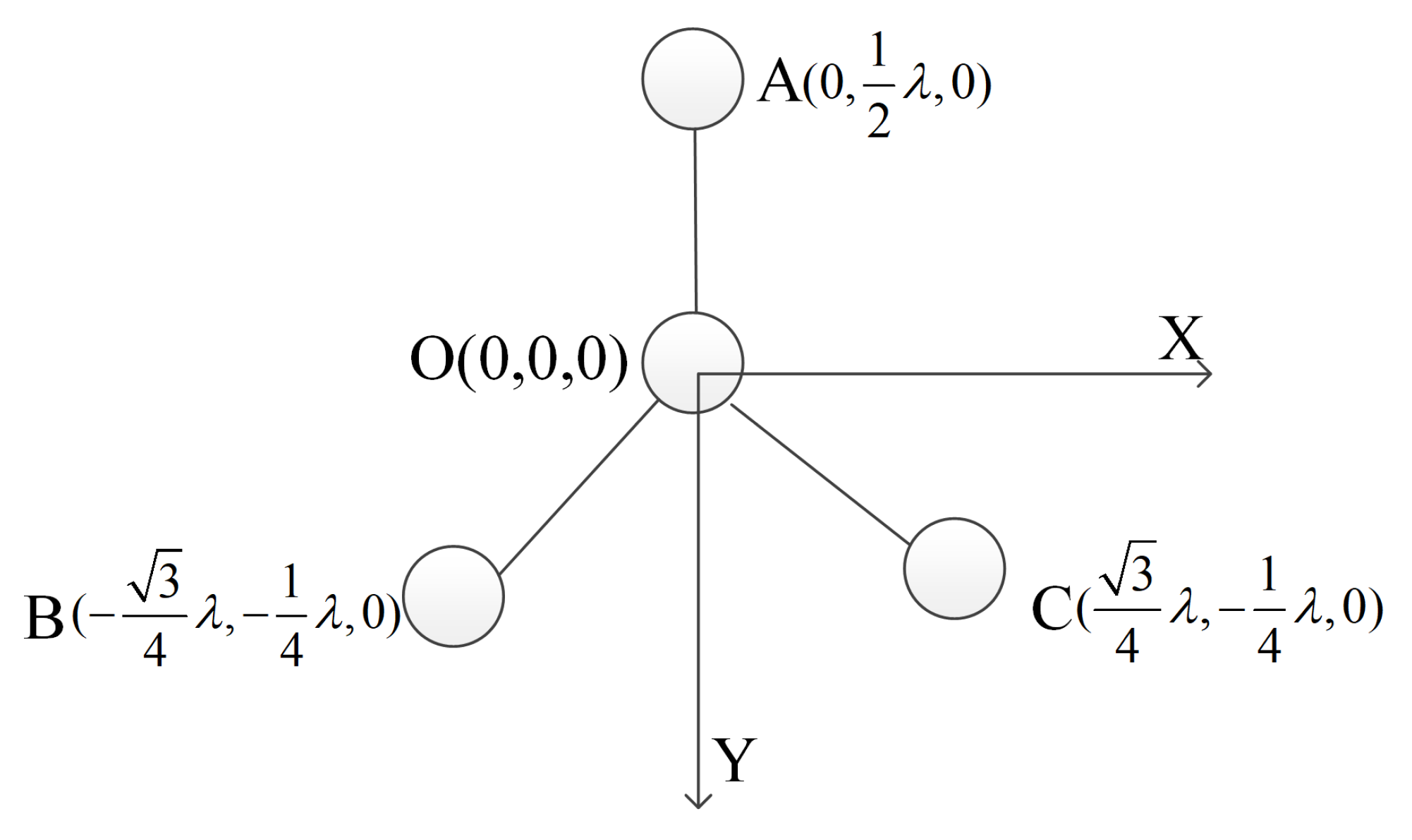
4.3. Spoofing-Direction-Finding: Half-Wavelength Baseline

Assuming that a four-element circular array antenna is used to complete high-precision direction-finding of spoofing, the array configuration and physical structure are shown in Figure 13.
To achieve high-precision direction-finding of spoofing with a half-wavelength baseline, it is necessary to correct the average differential phase-center deviation A O _ P C O and instantaneous differential phase-center A O _ P C V of antennas AO, BO, and CO. The procedures for calibration and the direction-finding methods are as shown in Figure 14.
The specific calculation steps for calibration and the direction-finding methods are as follows:
  • The spoofing sources are placed in different positions ( φ , θ ) , and the measurement matrix Δ P ( θ , φ ) of baselines OA, OB, and OC is measured by the receiver.
  • Calculate the differential baseline coordinate values of the stage baselines OA, OB, and OC, and A O _ P C O , B O _ P C O , and C O _ P C O are obtained according to Equation (18).
  • Calculate the differential instantaneous corrections and the differential instantaneous correction matrices A O _ P C V , B O _ P C V , and C O _ P C V related to ( φ , θ ) according to Equations (18) and (19).
  • Generate the average phase-center coordinate vector of the baselines OA, OB, and OC, and construct a differential instantaneous correction matrix [ A O _ P C V , B O _ P C V , C O _ P C V ] = P C V based on ( φ , θ ) .
  • Complete the preliminary measurement ( φ 1 , θ 1 ) of the direction of the spoofing using the A O _ P C O , B O _ P C O , C O _ P C O data, combined with Equation (11). The measured value includes the instantaneous differential phase error and can only provide a preliminary directional measurement result.
  • Set the incoming wave phase error intervals φ [ φ 1 D 1 , φ 1 + D 1 ] and θ [ θ 1 D 2 , θ 1 + D 2 ] , discretize the interval with Δ ξ , and calculate the correlation coefficient between the baseline phase difference and the wave path difference of OA/OB/OC using the equation in the next step.
    ρ ( φ i , θ i ) = n = 1 M cos ( Δ P n ( φ i , θ i ) Ψ n ( φ i , θ i ) × P C O n P C V n ( φ i , θ i ) Ψ n ( φ i , θ i ) × A R P n )
    Note that n = 1, 2, and 3, respectively, represent baselines OA, OB, and OC.
  • Using Δ ξ as the step, search and calculate all the correlation coefficients ρ ( φ i , θ i ) in the interval φ [ φ 1 D 1 , φ 1 + D 1 ] , θ [ θ 1 D 2 , θ 1 + D 2 ] and find the directional value corresponding to the largest correlation coefficient, which is the incident direction of the spoofing signal.
Using the interferometric measurement in step 5, the direction of the spoofing signal can be initially obtained. In steps 6 and 7, a high-precision directional measurement of the incoming wave can be achieved. Considering the varying performance characteristics of the array antennas from different manufacturers, it is essential to perform the corresponding array differential phase-center correction before applying the direction-finding of spoofing to ensure the accuracy and effectiveness of the method.

5. Experiments and Results

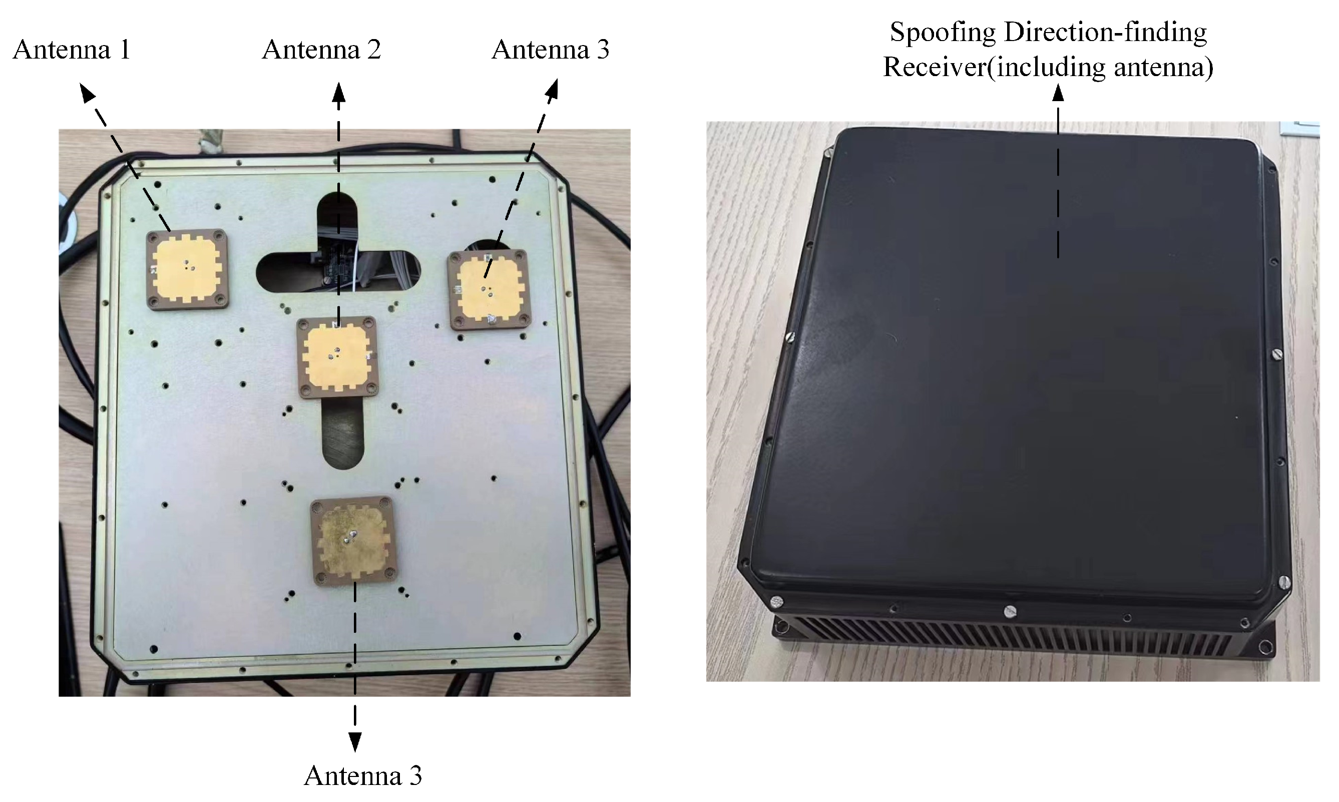
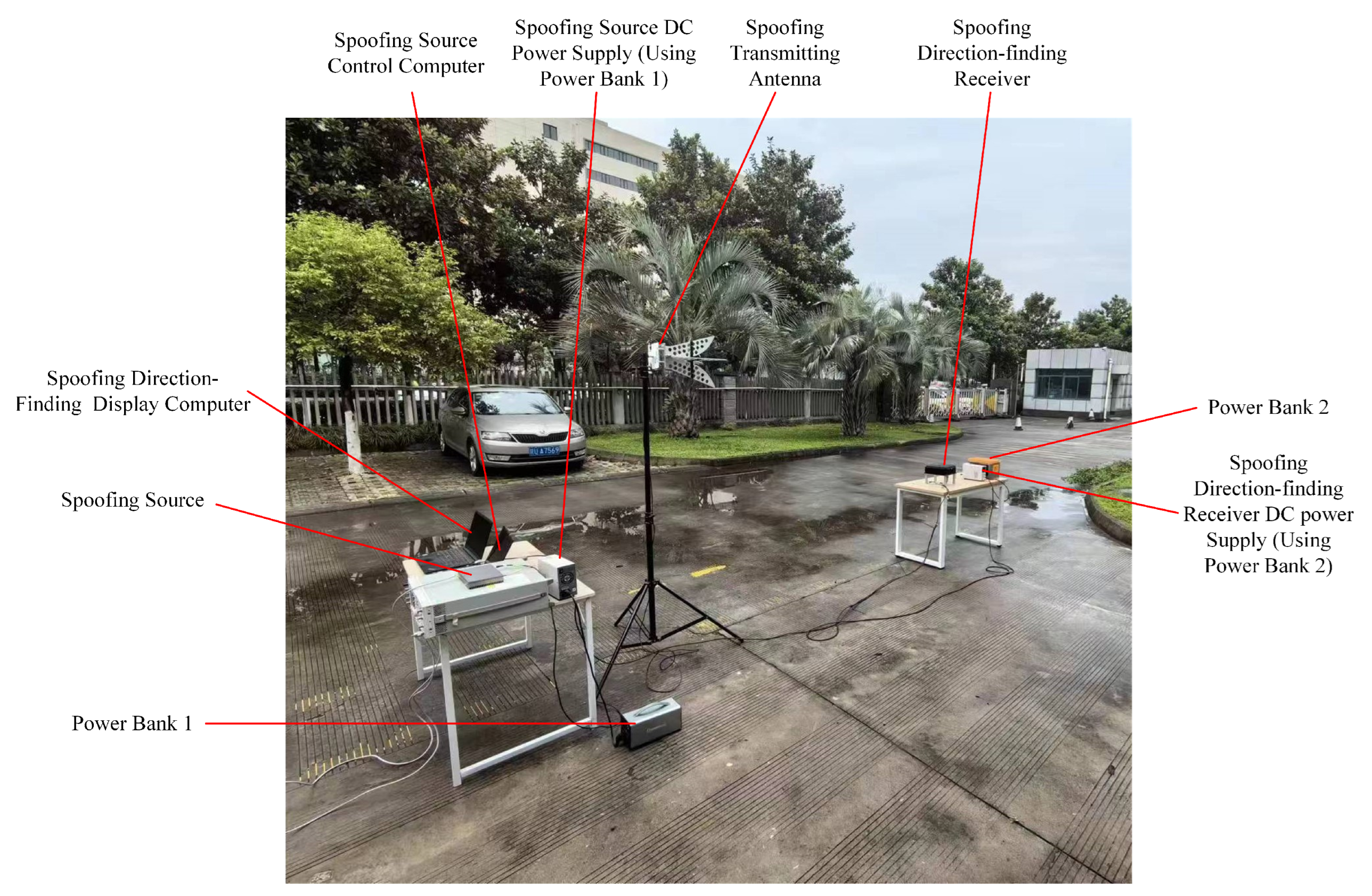
5.1. Experimental Scenario

Using the algorithm proposed in this paper, a spoofing detection and direction-finding receiver based on a four-element anti-jamming array antenna was developed. The distribution of the array antennas and the device are shown in Figure 15.
The flow patterns of the four-element array for the spoofing antenna, both before and after average differential phase correction, are shown in Table 3.
To verify the effectiveness of the proposed method, a real test environment was set up for experimental validation. The test scenario, depicted in Figure 16, includes a spoofing source, a spoofing transmitting antenna, a spoofing source DC power supply, a spoofing control and display computer, a spoofing detection and direction-finding device, a device DC power supply, a spoofing detection and direction-finding display computer, and two mobile power supplies.
The spoofing source is a generative device capable of adjusting the transmission power and code phase delay of the spoofing signal, as well as setting the position and time offset of the receiver to be deceived.

5.2. Experimental Results

To validate the spoofing detection method proposed in this paper, the transmission power of the spoofing signal was modulated within the range of −70 dBm to −30 dBm, employing an incremental step of 1 dBm. Two types of spoofing were considered: time spoofing and position spoofing. The code phase delay for generating the spoofing signal was varied between 0.5 and 3 chips. At the same time, the authentic signal data of the detection receiver in both moving and stationary scenarios were collected. After each test scenario stabilized, a 2 min test dataset was recorded. In total, 13 features used for spoofing detection were extracted from the test data every 0.5 s, resulting in a total of 12,513 test samples, including 6392 authentic signal samples and 6121 spoofing signal samples. The proposed method was then applied to these data, correctly identifying 12,042 samples with an accuracy rate of 96.24%. The confusion matrix for the measured data is illustrated in Figure 17.
To verify the spoofing-direction-finding method proposed in this paper, the spoofing signal power and chip delay are set to −30 dBm and 1 chip, respectively, while the transmission position is precisely calibrated using the RTK receiver. The incident angle of the spoofing signal is varied in 5-degree steps for each transmission position. The results of the measured path difference and theoretical path length for the spoofing-direction-finding array antenna with different baselines are shown in Figure 18. The horizontal axis represents the incident direction of the spoofing signal, and the vertical axis shows the measured carrier phase difference for baselines OA, OB, and OC in each incident direction.
Performing average differential phase correction on the baselines OA/OB/OC can effectively reduce the instantaneous measurement error of the baseline incident azimuth, as shown in Figure 18.
After correcting for channel deviation, the carrier phase difference trend for each baseline of the receiver closely matches the trend of the incident wave path difference, but there is an azimuth offset and some jitter. In the absence of average differential phase correction, the carrier phase observation error for each baseline, which is caused by antenna element characteristics and mutual coupling between elements, can be obtained by subtracting the measured carrier phase of each baseline from the theoretical wave path difference. As shown in Figure 18, the carrier phase observation error for the antenna baseline OB can exceed 45°, as shown in Figure 19.
After applying the average differential phase correction, the corrected baselines OA/OB/OC can achieve observation errors within 20° for different incident directions. When combined with the short-baseline interferometry method, half-wavelength baseline array spoofing can provide spoofing-direction-finding accuracy within 15°, as shown in Figure 20.
To effectively eliminate the impact of average differential phase error on direction-finding accuracy, the PCV (Phase-Center Variation) parameters for each baseline are derived based on the average phase differential correction results of the baselines OA/OB/OC. The maximum correlation coefficient between the incident direction and the PCV is discretized at regular intervals, allowing for accurate measurement of the incident direction.
In actual experiments, the overall direction-finding error remained within 15° through the average phase-center correction of the array antenna. After performing a second accurate search and correction using the PCV differential phase-center with a 0.5° resolution, the overall direction-finding accuracy was improved to within 1°.

6. Conclusions

To achieve sensitive and high-precision direction-finding for satellite navigation spoofing, it is first essential to detect the spoofing during the capture phase. This paper introduces a GNSS spoofing detection method based on the LightGBM machine learning algorithm, utilizing 13 features from the capture phase. The model has been trained and tested using the authoritative TEXBAT spoofing dataset, achieving a spoofing detection accuracy of over 97% on the test set. Additionally, data from real-world scenarios were acquired to further test and verify the method, which showed a spoofing detection accuracy exceeding 98%. The proposed method efficiently detects various types of spoofing, including large delay, small delay, and synchronous regeneration forwarding, during the capture phase.
This approach significantly reduces the influence of phase-center jitter, introduced by mutual coupling between half-wavelength antenna elements, on direction-finding of spoofing. It enables direction-finding for spoofing jamming using conventional half-wavelength anti-jamming arrays. Experimental verification using measured data was conducted for the proposed technology, with the results demonstrating that the direction-finding method can achieve an accuracy within 1°, enabling high-precision direction-finding of deceptive interference signals by traditional anti-jamming receivers.
Building on the successful spoofing detection in the capture phase, this paper also presents a spoofing-direction-finding method applicable to off-the-shelf GNSS anti-jamming zeroing antennas. By leveraging multi-element carrier phase observations from the array antenna, the differential phase-center is calibrated and corrected, thereby substantially reducing the effect of the phase-center jitter from the mutual couplings between half-wavelength antenna arrays. This allows for effective direction-finding of spoofing with conventional half-wavelength anti-jamming arrays. The experimental results demonstrate that the proposed method achieves direction-finding accuracy within 1°, enabling high-precision direction-finding of spoofing using traditional anti-jamming array antennas in a weak multipath environment. In the future, we plan to establish a typical multipath environment and further explore spoofing-direction-finding techniques in more challenging, stronger-multipath conditions.
The spoofing detection and direction-finding method introduced in this paper can be easily extended and applied to existing GNSS zeroing anti-jamming receivers. It holds significant practical value for direction-finding of spoofing and anti-spoofing applications.

Author Contributions

Conceptualization, R.J. and J.Y.; methodology, R.J. and X.C.; validation, R.J. and J.Y.; formal analysis, R.J., X.C. and H.Y.; investigation, M.G.; resources, G.J. and L.C.; data curation, H.L.; writing—original draft preparation, R.J.; writing—review and editing, R.J. and X.C.; visualization, J.Y.; supervision, W.Z. All authors have read and agreed to the published version of the manuscript.

Funding

This research was supported in part by the National Natural Science Foundation of China under Grant 52371354, in part by the National Key Laboratory Academician Fund Projects under Grant A392301035, and in part by Stabilization Support Projects for National Research Institutes under Grant A132301215.

Data Availability Statement

The raw data supporting the conclusions of this article will be made available by the authors upon request.

Conflicts of Interest

The authors declare no conflicts of interest.

References

  1. Humphreys, T. Statement on the Vulnerability of Civil Unmanned Aerial Vehicles and Other Systems to Civil Gps Spoofing; University of Texas at Austin: Austin, TX, USA, 2012; pp. 1–16. [Google Scholar]
  2. Androjna, A.; Perkovič, M. Impact of spoofing of navigation systems on maritime situational awareness. Trans. Marit. Sci. 2021, 10, 361–373. [Google Scholar] [CrossRef]
  3. Jones, M. Spoofing in the Black Sea: What really happened? GPS World. 11 October 2017. Available online: https://www.gpsworld.com/spoofing-in-the-black-sea-what-really-happened/ (accessed on 17 February 2025).
  4. Pany, T.; Falk, N.; Riedl, B.; Stöber, C.; Winkel, J.; Ranner, H.P. GNSS synthetic aperture processing with artificial antenna motion. In Proceedings of the 26th International Technical Meeting of The Satellite Division of the Institute of Navigation (ION GNSS+ 2013), Nashville, TN, USA, 16–20 September 2013; pp. 3163–3171. [Google Scholar]
  5. Dampf, J.; Pany, T.; Bär, W.; Winkel, J.; Mervart, L.; Ávila-Rodríguez, J.; Ioannides, R.; Hein, G. Real world spoofing trials and mitigation. Inside GNSS 2017, 12, 55–65. [Google Scholar]
  6. Mao, P.; Yuan, H.; Chen, X.; Gong, Y.; Li, S.; Li, R.; Luo, R.; Zhao, G.; Fu, C.; Xu, J. A GNSS Spoofing Detection and Direction-Finding Method Based on Low-Cost Commercial Board Components. Remote Sens. 2023, 15, 2781. [Google Scholar] [CrossRef]
  7. Yang, H.; Jin, R.; Xu, W.; Che, L.; Zhen, W. Satellite Navigation Spoofing Interference Detection and Direction Finding Based on Array Antenna. Sensors 2023, 23, 1604. [Google Scholar] [CrossRef] [PubMed]
  8. Jahromi, A.J.; Broumandan, A.; Nielsen, J.; Lachapelle, G. GPS spoofer countermeasure effectiveness based on signal strength, noise power, and C/N0 measurements. Int. J. Satell. Commun. Netw. 2012, 30, 181–191. [Google Scholar] [CrossRef]
  9. Broumandan, A.; Jafarnia-Jahromi, A.; Dehghanian, V.; Nielsen, J.; Lachapelle, G. GNSS spoofing detection in handheld receivers based on signal spatial correlation. In Proceedings of the 2012 IEEE/ION Position, Location and Navigation Symposium, Myrtle Beach, SC, USA, 23–26 April 2012; pp. 479–487. [Google Scholar]
  10. Tu, J.; Zhan, X.; Chen, M.; Gao, H.; Chen, Y. GNSS intermediate spoofing detection via dual-peak in frequency domain and relative velocity residuals. IET Radar Sonar Navig. 2020, 14, 439–447. [Google Scholar] [CrossRef]
  11. Shang, X.; Sun, F.; Wang, D.; Xiao, K.; Dou, S.; Lu, X.; Sun, J. GNSS spoofing detection based on multicorrelator distortion monitoring. GPS Solut. 2023, 27, 94. [Google Scholar] [CrossRef]
  12. Yang, Y.; Li, H.; Lu, M. Performance assessment of signal quality monitoring based GNSS spoofing detection techniques. In China Satellite Navigation Conference (CSNC) 2015 Proceedings: Volume I; Springer: Berlin/Heidelberg, Germany, 2015; pp. 783–793. [Google Scholar]
  13. Meurer, M.; Konovaltsev, A.; Cuntz, M.; Hättich, C. Robust joint multi-antenna spoofing detection and attitude estimation using direction assisted multiple hypotheses RAIM. In Proceedings of the 25th International Technical Meeting of the Satellite Division of the Institute of Navigation (ION GNSS 2012), Nashville, TN, USA, 21 September 2012; pp. 3007–3016. [Google Scholar]
  14. Magiera, J. A multi-antenna scheme for early detection and mitigation of intermediate GNSS spoofing. Sensors 2019, 19, 2411. [Google Scholar] [CrossRef] [PubMed]
  15. Konovaltsev, A.; Cuntz, M.; Haettich, C.; Meurer, M. Performance analysis of joint multi-antenna spoofing detection and attitude estimation. In Proceedings of the 2013 International Technical Meeting of The Institute of Navigation, San Diego, CA, USA, 27–29 January 2013; pp. 864–872. [Google Scholar]
  16. Daneshmand, S.; Jafarnia-Jahromi, A.; Broumandon, A.; Lachapelle, G. A low-complexity GPS anti-spoofing method using a multi-antenna array. In Proceedings of the 25th International Technical Meeting of the Satellite Division of the Institute of Navigation (ION GNSS 2012), Nashville, TN, USA, 17–21 September 2012; pp. 1233–1243. [Google Scholar]
  17. Liu, Y.; Li, S.; Fu, Q.; Liu, Z.; Zhou, Q. Analysis of Kalman filter innovation-based GNSS spoofing detection method for INS/GNSS integrated navigation system. IEEE Sens. J. 2019, 19, 5167–5178. [Google Scholar] [CrossRef]
  18. Tanıl, Ç.; Khanafseh, S.; Joerger, M.; Pervan, B. An INS monitor to detect GNSS spoofers capable of tracking vehicle position. IEEE Trans. Aerosp. Electron. Syst. 2017, 54, 131–143. [Google Scholar] [CrossRef]
  19. Bai, L.; Sun, C.; Dempster, A.G.; Zhao, H.; Feng, W. GNSS Spoofing Detection and Mitigation With a Single 5G Base Station Aiding. IEEE Trans. Aerosp. Electron. Syst. 2024, 60, 4601–4620. [Google Scholar] [CrossRef]
  20. Wesson, K.; Rothlisberger, M.; Humphreys, T. Practical cryptographic civil GPS signal authentication. NAVIGATION J. Inst. Navig. 2011, 59, 177–193. [Google Scholar] [CrossRef]
  21. Wu, Z.; Zhang, Y.; Liu, R. BD-II NMASSI: An scheme of anti-spoofing and open BeiDou II D2 navigation message authentication. IEEE Access 2020, 8, 23759–23775. [Google Scholar] [CrossRef]
  22. Iqbal, A.; Aman, M.N.; Sikdar, B. Machine and Representation Learning Based GNSS Spoofing Detectors Utilizing Feature Set From Generic GNSS Receivers. IEEE Trans. Consum. Electron. 2023, 70, 574–583. [Google Scholar] [CrossRef]
  23. Iqbal, A.; Aman, M.N.; Sikdar, B. A Deep Learning based Induced GNSS Spoof Detection Framework. IEEE Trans. Mach. Learn. Commun. Netw. 2024, 2, 457–478. [Google Scholar] [CrossRef]
  24. Chen, Z.; Li, J.; Li, J.; Zhu, X.; Li, C. GNSS multiparameter spoofing detection method based on support vector machine. IEEE Sens. J. 2022, 22, 17864–17874. [Google Scholar] [CrossRef]
  25. Humphreys, T.E.; Bhatti, J.A.; Shepard, D.; Wesson, K. The Texas Spoofing Test Battery: Toward a Standard for Evaluating GPS Signal Authentication Techniques; University of Texas at Austin: Austin, TX, USA, 2012. [Google Scholar]
  26. Kunysz, W. Antenna phase center effects and measurements in GNSS ranging applications. In Proceedings of the 14th International Symposium on Antenna Technology and Applied Electromagnetics & the American Electromagnetics Conference, Ottawa, ON, Canada, 5–8 July 2010; pp. 1–4. [Google Scholar]
  27. Kumar, A.; Sarma, A.D.; Ansari, E.; Yedukondalu, K. Improved phase center estimation for GNSS patch antenna. IEEE Trans. Antennas Propag. 2013, 61, 1909–1915. [Google Scholar] [CrossRef]
  28. Schmid, R.; Mader, G.; Herring, T. From relative to absolute antenna phase center corrections. In Proceedings of the IGS Workshop and Symposium 2004, Bern, Switzerland, 1–5 May 2005; pp. 209–219. [Google Scholar]
Figure 1. Hardware architecture.
Remotesensing 17 00864 g001
Figure 2. Algorithm procedure.
Remotesensing 17 00864 g002
Figure 3. Capture results without spoofing. (a) Two-dimensional capture results. (b) Side view of capture results in code phase dimension.
Remotesensing 17 00864 g003
Figure 4. Capture result when the spoofing signal and the real signal differ by 1.1 chip time delay. (a) Two-dimensional capture results. (b) Side view of capture results in code phase dimension.
Remotesensing 17 00864 g004
Figure 5. Capture results of spoofing signals containing real signals and code phase delay of 0.5 chips. (a) Two-dimensional capture results. (b) Side view of capture results in code phase dimension.
Remotesensing 17 00864 g005
Figure 6. Data distribution of real signals and spoofing signals.
Remotesensing 17 00864 g006
Figure 7. Heat map of feature correlation.
Remotesensing 17 00864 g007
Figure 8. The obtained ROC curve.
Remotesensing 17 00864 g008
Figure 9. Training set confusion matrix.
Remotesensing 17 00864 g009
Figure 10. Test set confusion matrix.
Remotesensing 17 00864 g010
Figure 11. Schematic diagram of array antenna direction-finding structure (long- and short-baseline and circular array, OE is the direction of the spoofing signal, OE1 is the projection of OE in the OXY plane, OE2 is the projection of OE in the OYZ plane).
Remotesensing 17 00864 g011
Figure 12. Differential phase-center array model (dual antennas).
Remotesensing 17 00864 g012
Figure 13. Schematic of a 4-element circular array antenna.
Remotesensing 17 00864 g013
Figure 14. Four-array element, half-wavelength baseline direction-finding of spoofing.
Remotesensing 17 00864 g014
Figure 15. Spoofing-direction-finding antenna array: element distribution and host.
Remotesensing 17 00864 g015
Figure 16. The test scenario.
Remotesensing 17 00864 g016
Figure 17. Test set confusion matrix of actual measured data.
Remotesensing 17 00864 g017
Figure 18. Baseline OA/OB/OC wave range difference observation error (different incident directions).
Remotesensing 17 00864 g018
Figure 19. Baseline OA/OB/OC carrier phase difference observation error.
Remotesensing 17 00864 g019
Figure 20. Short-baseline interferometry direction-finding accuracy after average differential phase-center correction.
Remotesensing 17 00864 g020
Table 1. Description of TEXBAT data involved in modeling and training.
Abrv.Scenario InfoSpoofing TypeMobilityPower Adv. (dB)SynchronizationOnset (s)
DS-00: Clean-StaticN/AStaticN/AN/AN/A
DS-11: Clean-DynamicN/ADynamicN/AN/AN/A
DS-22: Static OverpoweredTime PushStatic10Code Phase Prop.110
DS-33: Static Matched-PowerTime PushStatic1.3Frequency Lock Mode120
DS-44: Static Matched-PowerPosition PushStatic0.4Frequency Lock Mod114
DS-55: Dynamic OverpoweredTime PushDynamic9.9Code Phase Prop.102
DS-66: Dynamic Matched-PowerPosition PushDynamic0.8Frequency Lock Mod105
DS-77: Static Matched-PowerTime PushStaticMatchedCarrier Phase Aligned110
DS-88: Static Matched-PowerTime PushStaticMatchedZero-Delay Security
Code Estimation and Replay
110
Table 2. Comparison of the spoofing detection results.
MethodFeature Extraction PhaseAUCAccuracyPrecisionRecallF1
ProposedAcquisition0.995297.1598.8296.2797.09
Ref. [24]Tracking and
PVT solution
0.9997.0296.7797.2497.00
Table 3. Spoofing-direction-finding equipment: 4-element array antenna parameters.
Element NumberX Axis (mm)Y Axis (mm)Z Axis (mm)Explain
O000Reference origin
A0840Reference origin
B−72.7−420Reference origin
C72.7−420Reference origin
OA9.5381.250.0718Average differential phase correction
OB−0.8331−13.44130.75Average differential phase correction
OC−14.947.04−84.12Average differential phase correction
Disclaimer/Publisher’s Note: The statements, opinions and data contained in all publications are solely those of the individual author(s) and contributor(s) and not of MDPI and/or the editor(s). MDPI and/or the editor(s) disclaim responsibility for any injury to people or property resulting from any ideas, methods, instructions or products referred to in the content.

