Abstract
The solar radiation pressure (SRP) model, as a key factor affecting the precise orbit determination (POD) accuracy of navigation satellites, is related to the state and optical properties of the satellite surface. This study establishes a high-precision SRP model for BDS-3 medium earth orbit (MEO) satellites manufactured by the China Academy of Space Technology based on the satellite engineering parameters, which comprises the satellites’ size and optical properties measured before launch. Then, the physical-based SRP model is re-constructed into the body-fixed coordinate as the function of the Sun elongation angle. The use of the hybrid SRP model, combining the reconstructed SRP model and the 5-parameter ECOM, results in a better POD performance. The orbit results, validated using satellite laser ranging (SLR) observations, show that the radial precision of approximately 3–4 cm can be achieved, with a reduction of the bias by up to 38% and a removal of the systematic error related to the Sun elongation angle in SLR residuals. Considering the possible degradation of the reconstructed SRP model with the engineering parameters, the evolution of SRP accelerations along with orbit quality based on a time series from over 5 years was studied. The results indicate that a variation of the total SRP acceleration for the BDS-3 satellites is minor and there is no apparent degradation in validations of 2019–2023, which proved the reliability and usability of the proposed SRP model for the BDS-3 MEO satellites.
1. Introduction
The Global Satellite Navigation System (GNSS) is a space-based radio system that can provide all-weather, all-day, and high-precision positioning, navigation, and timing (PNT) services to various users on the Earth’s surface or in near-Earth space. As one of the Big Four GNSSs, the China third generation BeiDou system (BDS-3) has officially provided global PNT services since 31 July 2020 [1]. The high-precision orbit of GNSS satellites can provide centimeter-level absolute and millimeter-level relative positioning information. It is the basis for realizing a dynamic terrestrial reference frame, which is one of the core tasks of modern geodesy. For the precise orbit determination (POD) of GNSS satellites, much research was carried out in modeling and refining orbit dynamic models, especially in solar radiation pressure (SRP) perturbating force, which is the largest, with an acceleration of over 100 nm/s2, and the most challenging non-gravitational force acting on a GNSS satellite [2].
There are mainly three types of SRP models proposed since the 1980s in the POD of GNSS satellites. The first type is the analytical model, which considers the satellite illumination conditions and incident and reflected light paths based on the satellite metadata of size and surface optical parameters. The ROCK models [3,4] and the UCL model [5] are typical examples of the analytical SRP model. The second type is the empirical model, which uses certain modeling terms in a specific coordinate system to empirically absorb the SRP accelerations. The ECOM [6] series which comprises three constant and six periodic terms in a Sun–satellite–Earth frame called DYB, constructed and developed at the CODE (Center for Orbit Determination in Europe), has been adopted since the 1990s and then the 5-parameter ECOM (ECOM5 [7]) with three constants in DYB as well as two periodic terms in the B direction, and the extended ECOM (ECOM-2 [8]) with up to 9 parameters are widely utilized in the POD within the GNSS community. The last type is the semi-analytical or semi-empirical models, which take into account both the geometry and physical properties of satellites and the contribution of tracking data. A feasible approach is the adjustable box-wing model (ABW [9]), using pre-launch measured information as initial values and employing tracking observations to estimate optical coefficients and relevant parameters.
For the SRP modeling of BDS satellites, efforts were initially made for the BDS-2 satellites with orbit-normal yaw mode, as the ECOM-like models are designed and applied assuming GNSS satellites are in yaw-steering mode [10,11]. For BDS-3 satellites, the 5-parameter ECOM has been widely used; however, the satellite laser ranging (SLR) validations show obvious linear systematic errors with respect to the Sun elongation (ε) angle for BDS-3 MEO satellites manufactured by the China Academy of Space Technology (CAST) and Shanghai Engineering Center for Microsatellites (SECM) [12]. Similar to Galileo, this pattern is possibly caused by the cuboid shape of satellites with a relatively high area-to-mass ratio [13] and could be reduced by using the 7-parameter ECOM-2 [8,14] or an a priori semi-analytical model [12,15]) as well as a box-wing model based on the released or calibrated metadata information [16,17]. In summary, the research on the refinement or improvement of the SRP for BDS satellites can be summarized into the following three aspects: the first is to adjust model coefficients based on the ECOM [18,19]; the second is to add additional parameters to absorb unmodeled orbit dynamic errors [10,20]; and the third is to construct a prior SRP model [16,21,22,23,24]. However, the SRP perturbation force is related to the satellite’s on-orbit state and the optical parameters of surface materials. The latter will age and degrade to some extent with the accumulation of on-orbit time. Hence, further evaluation of the changes in satellite surface optical coefficients is required to ensure POD accuracy over long time spans. In addition, the BDS-3 metadata for SRP modeling was released, though some key parameters are missing [25].
In this contribution, we established a high-precision analytical SRP model for BDS-3 MEO satellites using satellite engineering parameters, i.e., the satellites’ size and surface optical properties measured before launch. The use of this a priori model combined with the ECOM5 could thus properly model the SRP acceleration and help remove the systematic orbit error that affected the BDS-3 POD. On this basis, the evolution of SRP acceleration based on a time series from over 5 years was studied, which can provide a useful reference for an in-orbit evaluation of the satellite SRP model along with research on the reliability of the model.
2. Analytical SRP Modeling of BDS Satellites
SRP refers to the energy conversion of solar photons that are reflected or absorbed after colliding with satellite bodies and solar panels. The SRP force depends on factors such as satellite structure, the optical parameters of surface components, and the yaw attitude mode, making it challenging to model accurately.
2.1. Satellite Body-Fixed Frame
In order to properly describe the orientation of a satellite, a body-fixed coordinate is in need to be formed. This frame is tied to the payload of the satellite and specificities the locations of antenna and the Laser ranging Array (LRA) relative to the center of mass. This frame is also the basis for establishing an analytical SRP model. The definition of the satellite body-fixed coordinate for BDS satellites is as follows: The origin is the satellite center of mass, the +Z axis is perpendicular to the Earth, and the +Y axis is along the direction of the solar panel. The +X axis, +Y axis, and +Z axis complete a right-handed system, which is in line with the International GNSS service (IGS) convention [26,27]. Currently, 14 MEO satellites manufactured by CAST are active, in addition to 10 MEO satellites made by SECM also in operation as shown in Table 1. There are a total of six BDS-3 MEOs that are equipped with a Search and Rescue (SAR) antenna in the +X direction in the satellite body-fixed coordinate, which enlarges the illuminated area in the +Z direction and also causes the shadowing effect when modeling the SRP.

Table 1.
The information of BDS-3 MEOs manufactured by CAST and SECM (with or without SAR).
In addition to the frame system, the directions of each axis are also important for SRP modeling as they affect the orientation of the SRP force. To maintain the ground-pointing of the navigation antenna and the Sun-pointing of the solar panel, the attitude and orbit control subsystem adopts a continuous yaw maneuver and active control of the solar panel. The three-axis attitude closed-loop control is carried out by the reaction wheels, relying on the magnetic torque converter for angular momentum management. The goal of satellite yaw attitude control is to keep the Sun vector in the XOZ plane of the satellite body coordinate system with a yaw-steering or a nominal yaw attitude. When the angle between the solar vector and the orbital plane (denoted as angle) is less than 3°, the yaw angle is controlled according to the preset angle with continues yaw attitude mode [25].
2.2. Satellite Engineering Data of BDS-3 MEOs
The coefficients for SRP modeling can be found in the “Definition and Description of High Precision Application Parameters for BDS Satellite” section released by the China Satellite Navigation Office (CSNO). However, only the absorption () and areas of the satellite are available in this document; information on the diffuse reflection () and specular reflection () parameters are missing. In this contribution, the satellite engineering data including the shape, area, and optical parameters of the satellite surface are provided as in Table 2.
Table 2.
Satellite engineering data for SRP modeling (shape, area, and optical properties).
Note that different from the three optical parameters presented in the metadata (CSNO, 2019), the optical properties are expressed with two parameters in this study, the reflectivity coefficient () ranging from 0 (black) to 1 (white); and the specularity coefficient () ranging from 0 (diffuse) to 1 (specular). The conversion between the two sets of optical parameters are shown as follows:
For +X surface, utilizing reflectivity coefficient () with 0.65 and specularity coefficient () with 1, the optical parameters of , and can be easily obtained using the above equations with 0.35, 0.65, and 0, respectively. The missing properties of and values in the CSNO released metadata could thus be compensated. Furthermore, these satellites adopt an overall configuration of a satellite body and two wings, while the details on the additional search and rescue (SAR) antenna are missing. The satellite body is designed with a T-shaped box structure with +X and −Z surfaces covered by Multi-Layer Insulations (MLIs) and +Y and −Y surfaces Optical Solar Reflectors (OSRs). As aforementioned, only the satellite engineering data for the MEOs manufactured by the CAST were utilized as listed in Table 1. Hence, the analysis of BDS-3 GEO/IGSO and other MEOs along with the enlarged illuminated area and shadowing effect of the SAR antenna is not included in this study.
2.3. Theorical Foundations for the Modeling of the SRP
The analytical or physical interpretation of the SRP force originates from Einstein’s special theory of relativity. It provides the relationship between energy, mass, and momentum, from which the relationship between radiation energy and the incident force of solar pressure can be derived, as follows:
where is the solar radiation constant in W/m2, is the area of illuminated components in m2, is the angle between the incident light and the normal of the illuminated surface, and is the speed of light in a vacuum.
For any surface component, the optical reflectivity is denoted by , and the specularity (or called mirror coefficient) by . Among all incident photons, the proportion of absorbed photons is , the proportion of specular reflected photons is , and the proportion of diffuse reflected photons is . By synthesizing and solving the SRP generated by absorption, specular reflection, and diffuse reflection, the normal () and tangential () forces acting on surface components under sunlight irradiation can be obtained.
The above expression can be transformed into another equivalent vector form by Equation (1), that utilizes the of absorption (), reflectivity (), and diffusion () with and , the surface normal and satellite–Sun directions, respectively, as follows:
Considering that absorbed radiation is instantaneously radiated according to Lambert’s law typically for satellites covered by MLI, the SRP force can be obtained as follows:
2.4. The Analytical SRP Model with Model Parameterization
In order to develop an analytical SRP model, the following steps were applied. Firstly, establish a surface component parameter library that includes the installation information of satellite surface components, such as shape, boundary, area, surface reflection coefficient, surface mirror coefficient, etc. Next, set the angle between the Sun vector and the satellite’s +Z axis as 0°, then follow the Sun vector’s motion with a fixed step interval of 5° to establish the relationship between the Sun–satellite illumination within the maximum envelope of the Sun vector’s motion range. Thirdly, calculate the SRP forces of each surface component for every Sun vector using ray tracking and occlusion projection analysis. It is similar to the ray-tracing method developed by [5] at UCL. Afterwards, synthesize and compute the combined SRP forces of all surface components along the X, Y, and Z axes of the satellite body, along with thermal radiation and the Earth’s albedo force [28,29]. Finally, fit these perturbation forces or accelerations to obtain a mathematical model based on the step size of solar vector motion.
Based on the temperature and emission coefficient of each surface component, this study has completed the simulation on satellite thermal radiation. The satellite ±Y panels was served as a symmetrically distributed heat dissipation plate [30,31]. The thermal radiation acceleration in the X and Z directions varied with the temperature changes of the external components caused by the solar vector irradiation on the satellite surface. Earth’s albedo radiation originates from solar radiation energy reflected from the Earth in two distinct ways after absorbing radiation from the Sun. These methods include infrared radiation and optical radiation.
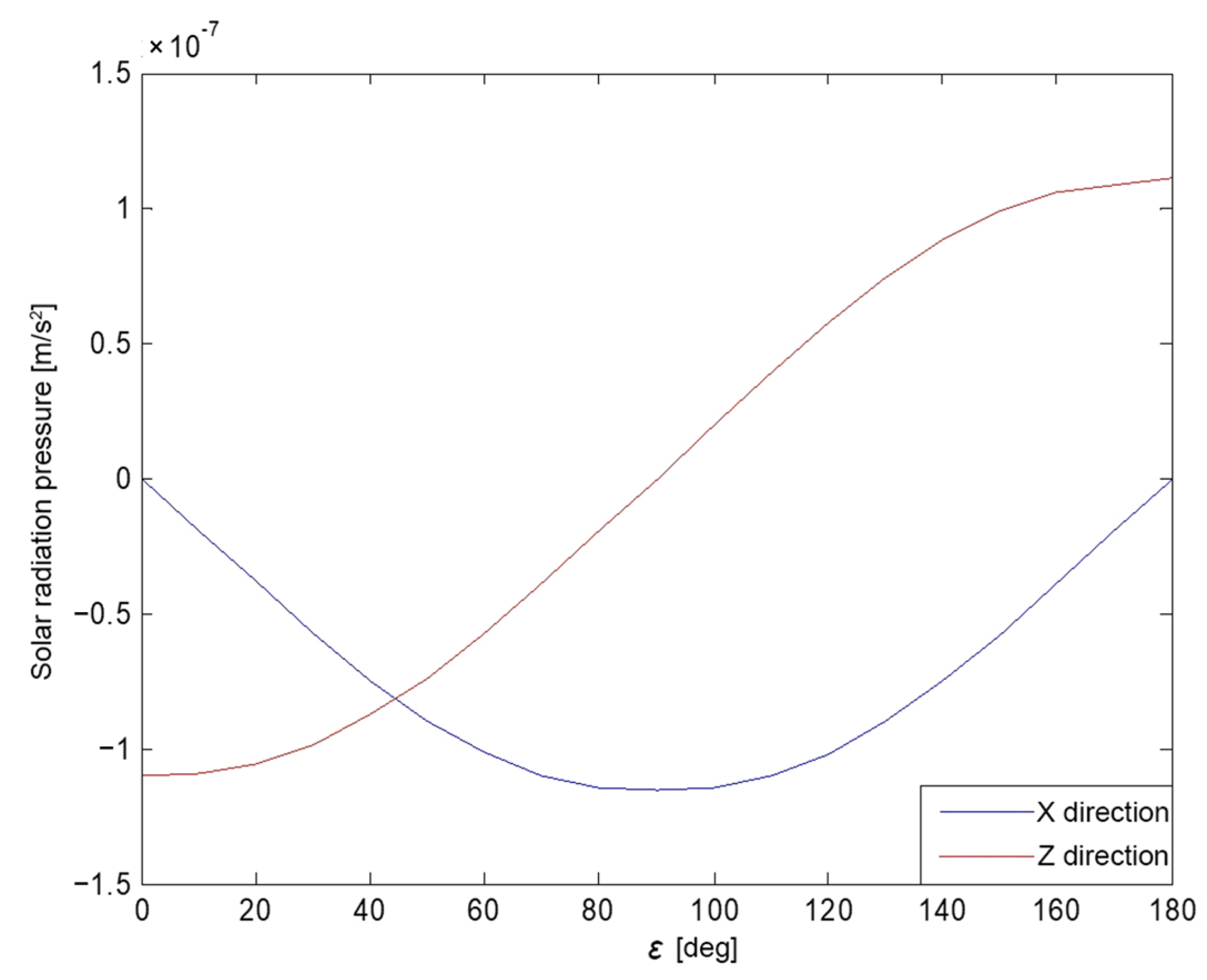
The variation of the solar vector in the body-fixed coordinate system over a period of time was analyzed. The angle between the Earth, satellite, and Sun (i.e., the angle between the Sun vector and the +Z axis in the body-fixed coordinate system) was chosen as the independent variable, denoted as . That is similar to most analytical models derived from physical theory, as the angle can capture the relational dynamics among Earth, spacecraft, and the Sun with just a single parameter. The total of the solar radiation acceleration on all surface components of the satellite was then calculated. The X and Z components of the SRP accelerations varying with angle is shown in Figure 1. Theoretically, the Y surface is not illuminated by the Sun under the nominal yaw control mode and the perturbation generated by the SRP in the Y direction was zero.
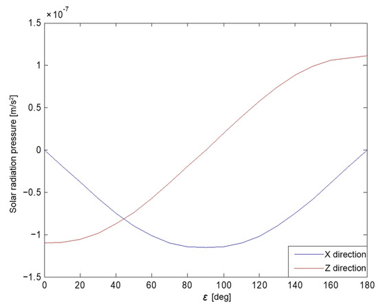
Figure 1.
The analytical SRP acceleration in the X and Z directions for C20 with respect to the angle.
Finally, the Fourier polynomials were used to mathematically express the SRP acceleration results in the X, Y and Z directions in a body-fixed frame, and the coefficients of the Fourier polynomials were obtained using the least squares method. As the analytical model developed in this study was conducted with the angle between the Sun vector and the satellite’s +Z axis, i.e., the angle, so we choose it as a critical argument to present the SRP force, in which the SRP can be clearly modeled with only one such parameter, just as most analytical models did. Taking into account both the fitting accuracy and the convenience of the mathematical results, a first-order of Fourier terms in the satellite body-fixed coordinate including the contribution of the elongated or stretched satellite body modeling was utilized and the output of the analytical SRP model for BDS-3 CAST MEOs. It could be represented in the body-fixed coordinate for the X and Z acceleration components as the function of the angle in the following:
The SRP accelerations modeling of the BDS-3 CAST MEO satellites without the SAR antenna can then be performed using Equation (7) in m/s2. To account for discrepancies between the analytical model and actual SRP accelerations caused by the unsymmetrically thermal radiation, e.g., a shear component of the SRP force when solar panels are not perfectly normal to the sunlight, along with the non-nominal orientation of the satellite or other unexpected cases, additional parameters should be introduced into the POD to mitigate these errors, while the reconstructed SRP model might present similar to the macro model (e.g., box-wing model) but with a concise and simple form in use. In view of simplicity, the reconstructed SRP model is not intended as a stand-alone model but combined with a ECOM-type empirical acceleration model to account for remaining unmodeled accelerations. In practice, a hybrid model with the reconstructed SRP using Equation (7) on top of the empirical SRP model naturally absorbs the constant or periodic errors in the DYB frame.
3. SRP Model Analysis and Validations
This section presents an analysis and comparison of the performance of the ECOM5+CAST (5-parameter ECOM enhanced by the reconstructed SRP model in the previous section) model and the stand-alone ECOM5 model for BDS-3 CAST MEOs.
3.1. Strategies of Precise Orbit Determination
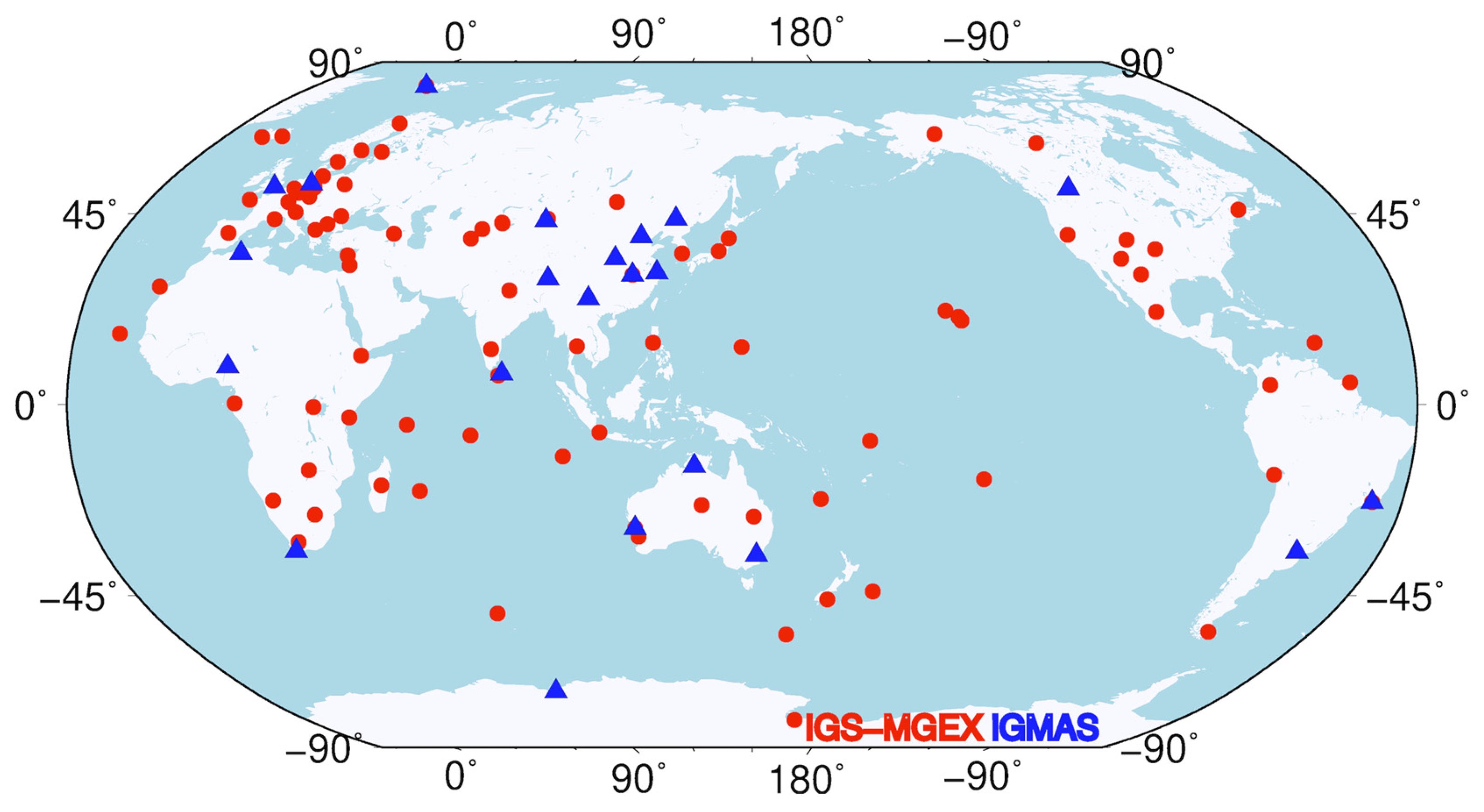
The observations were collected from approximately 110 global stations in the IGS and International GNSS Monitoring and Assessment System (iGMAS) [32] tracking station networks, as shown in Figure 2. Data processing in this study utilized a revised version of PANDA (Position and Navigation Data Analysis) software [33]. The observation data sampling interval for the POD was 300 s. In terms of orbit dynamics models, besides conservative perturbations like the Earth’s gravity field, N-body gravity, and Earth’s solid tide, non-gravitational models primarily include the SRP model for GNSS satellites. Due to the limitations of the classical 5-parameter ECOM SRP model for BDS satellite POD, this study employed a hybrid model combining the proposed analytical model and ECOM5 model with scaling factors, Y bias, and other empirical terms to mitigate residual SRP discrepancies.
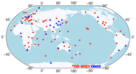
Figure 2.
A distribution map of ground tracking stations (red dots indicate IGS-MGEX stations and blue triangles are iGMAS stations).
Regarding observation models, the first-order ionospheric delay was mitigated using a dual-frequency Ionosphere-free combination of the phase and code observations. The zenith tropospheric delay over tracking stations was corrected using a prior model and parameter estimation method that utilized the Saastamoinen zenith delay model and the global mapping function (GMF). The wet delay was estimated every two hours in the zenith direction. The ambiguity resolution was performed with a double-difference method and the detailed strategies for the POD are summarized in Table 3.
Table 3.
A summary of precision orbit determination strategies.
3.2. Model Validations
Based on the considerations and information described above, the SRP modeling of the BDS-3 CAST MEO satellites using the a priori model in Equation (7) was studied. In order to assess the impact of the constructed SRP model on the determined orbit quality, metrics including SLR validation and orbit boundary disclosures (OBD) are utilized, along with analyzing characteristics of the SRP model coefficients.
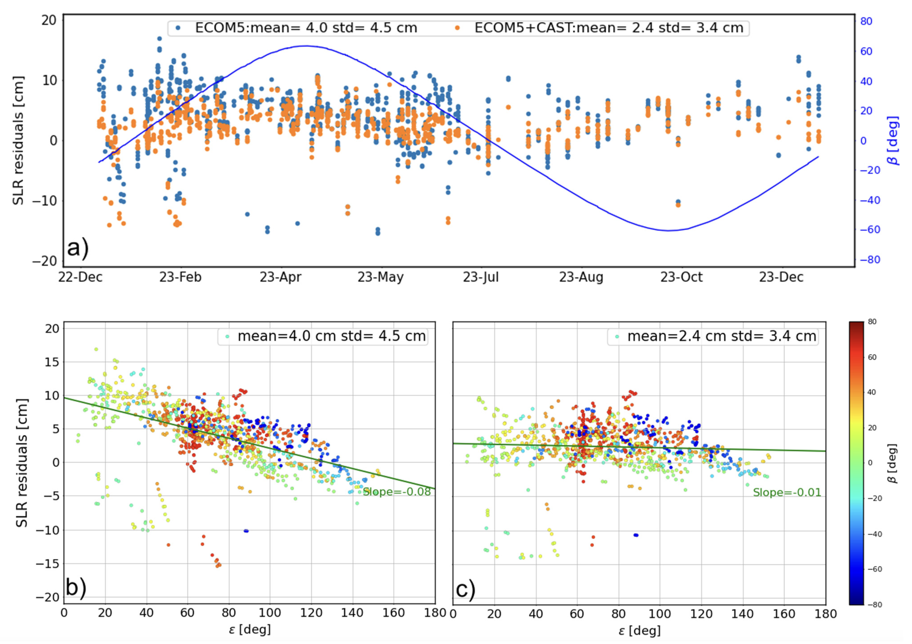
As the external validation method, SLR can directly reflect the accuracy of the orbit, particularly in the radial direction. During the study period of this study (2019–2023), although all 24 BDS-3 MEO satellites are currently included in the international laser ranging service (ILRS [38]), only four BDS-3 MEOs of C20–C21 and C29–C30 were tracked for a long period of time. Fortunately, all the BDS-3 MEOs were tracked by ILRS since early 2023. To address the impact of the proposed SRP model, SLR residuals for C20 are shown in Figure 3, along with statistics of the mean and standard deviation (STD) values list in Table 4. As can be seen in Figure 4a, the hybrid SRP model incorporating 5-parameter ECOM and the proposed priori CAST SRP model shows less scattered results and further reduces the bias in SLR residuals. Validation results in 2023 demonstrate that compared to the 5-parameter ECOM model without a prior CAST model, the mean and STD values have decreased by around 35% for C21 and approximately 29% for all the BDS-3 CAST MEOs as listed in Table 4. This indicates that the constructed analytical SRP model significantly reduces bias and improves orbit accuracy, as evidenced by the SLR residuals.

Figure 3.
The variation of the SLR residuals of C20 of (a) the time series and with respect to the Sun elongation angle in the (b) ECOM5 and (c) ECOM5+CAST solution (the blue curve represent the variation of the Sun elongation angle, i.e., angle).
Table 4.
Statistics of SLR residuals for solutions using ECOM5 and ECOM5 enhanced by the CAST model (ECOM5+CAST) (unit: cm).
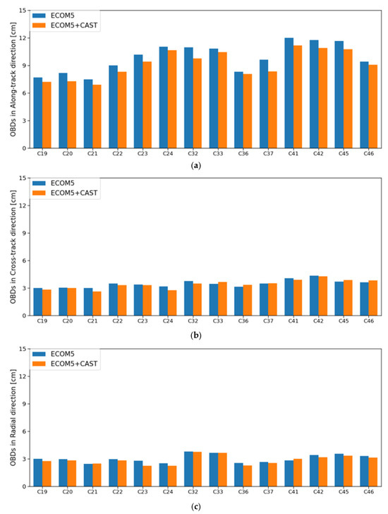
Figure 4.
Statistics of OBDs for BDS-3 CAST MEO satellites in (a) along-track, (b) cross-track, and (c) radial directions.
It is also interesting to note the different pattern of the SLR residuals for two sets of satellites with a SAR antenna onboard, i.e., C32–C33 and C45–C46. The general SRP model proposed in this study does not take the SAR antenna into consideration, though it contributes to the improvement of C32 and C33. While it is not the case for C45 and C46, the enlarged illuminated and shadowing effect caused by the extra SAR antenna can be explained by accounting this with the refined SRP model as did the authors in [14], and additional efforts should be made towards C32 and C33, which also employed a SAR antenna, but this is beyond the slope of this study.
Importantly, combining the analytical SRP model using Equation (7) with the 5-parameter ECOM for BDS-3 CAST MEOs significantly reduces systematic errors related to the angle compared to using only the stand-alone ECOM5 solution (see Figure 4b,c). This adjustment reduces the slope from −0.08 to −0.01, thereby enhancing the absolute orbit accuracy, as illustrated in Figure 3.
As an internal validation method, OBDs are typically employed as an internal validation method by comparing 3D position differences at a specific epoch. Essentially, this approach is similar to overlapping orbit validations to evaluate the consistency of consecutive orbits, while it could avoid further correlations between the adjacent orbit arcs. In this study, two POD arcs with a single common midnight epoch were selected. Figure 4 displays the mean Root Mean Square (RMS) of daily OBDs in along-track, cross-track and radial directions for the BDS-3 CAST MEO satellites during the test period. As can be seen, the hybrid model combining the proposed analytical model and ECOM5 improves intra-orbital alignment accuracy by 1–2 cm generally in the along-track direction, with a marginal enhancement of approximately 5% compared to the solution using solely the ECOM5 model. One might notice that the OBDs in the along-track direction is the largest among all the three directions, though it obtains more clear improvements possibly due to fact that the incorporated CAST SRP model provides preliminary modeling for thermal radiation based on two characteristics of the material, in particular the +X direction, which is illuminated by the Sun heat and is in line with the orbit along-track direction. Compared to the validation results by SLR measurements, this improvement is relatively minor. This phenomenon aligns with results from the Galileo satellite orbit determination using the 5-parameter ECOM and the a priori box model [39], as the orbit errors are highly correlated from one day to the next and this correlation would thus help to reduce statistics for the internal validation metrics.
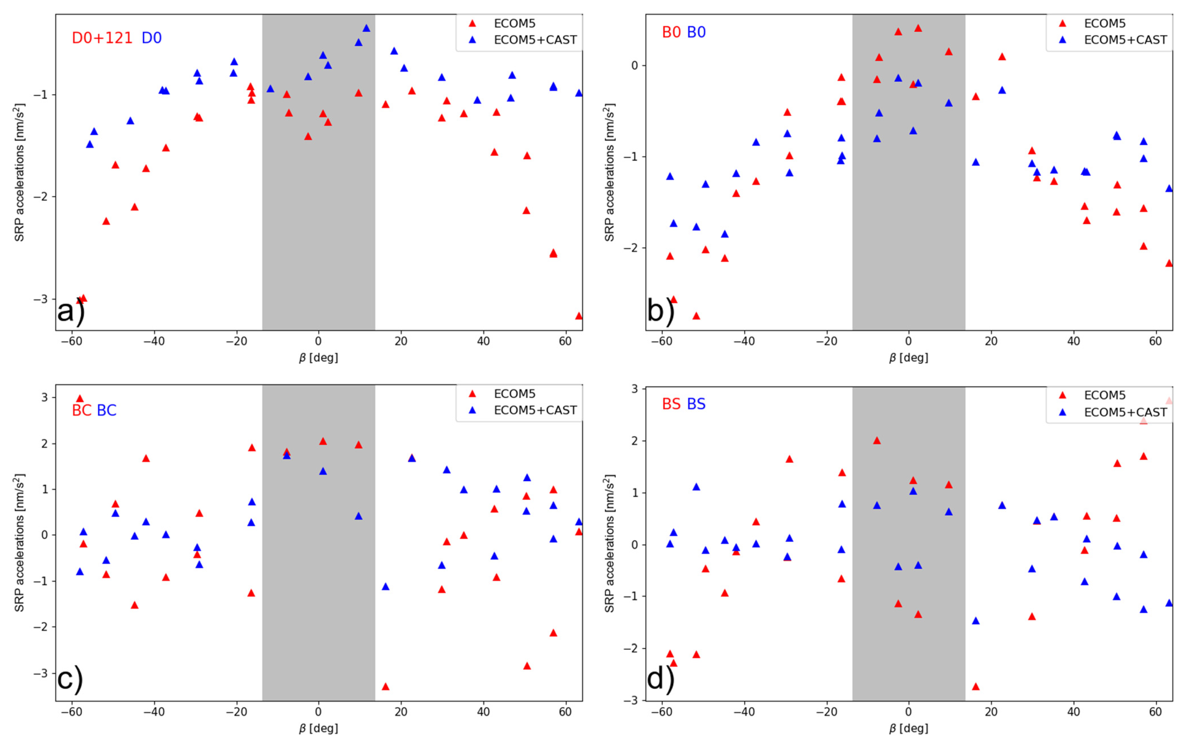
The variation of the estimated terms in the empirical SRP model could be used to evaluate the model usability. As illustrated in Figure 5, the use of the reconstructed priori SRP model evidently lowers the scatter of the estimated model parameters in ECOM5 and further reduces the dependence with respect to the angle, especially in the estimated constant term in the D direction in the ECOM5 model. For the constant, cosine, and sine terms, the near zero value would be expected. However, the residual variation might still be noticed, even though their amplitude is lower than that for the ECOM5-only solution. The differences between the constant term in the Y direction is as minor as 0.1 nm/s2.
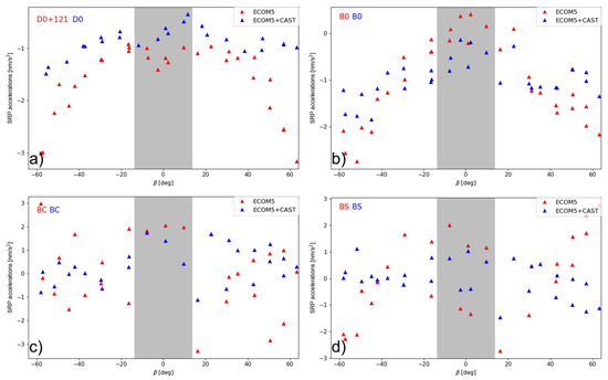
Figure 5.
Estimated ECOM5 model parameters. (a) The constant term in the D direction; (b) the constant term in the B direction; (c) the cosine term in the B direction; and (d) the sine term in the B direction of the C20 satellite w/o the a priori model as a function of the orbital elevation angle above the orbital plane. (The gray-shaded area represents the eclipse season).
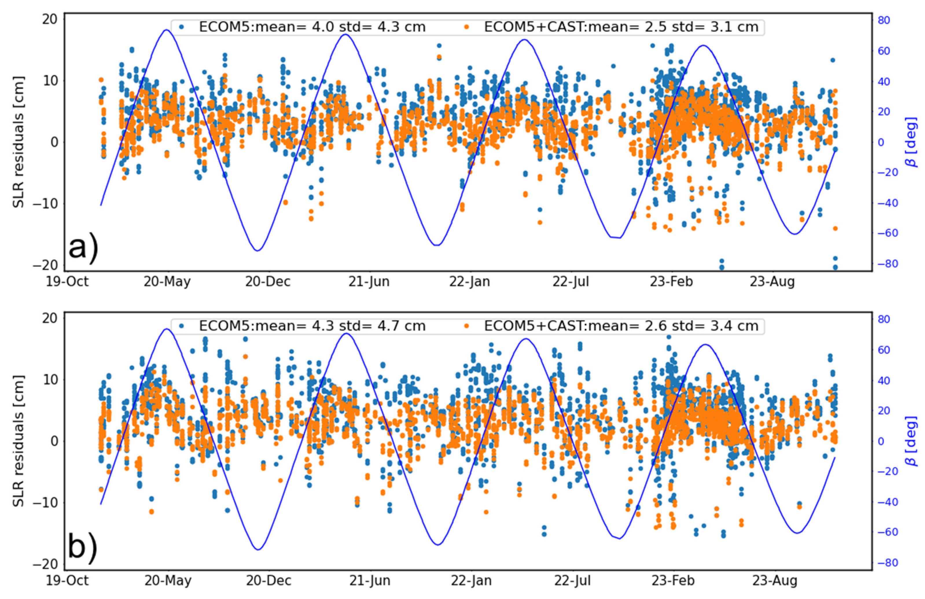
Given factors such as the space environment, radiation, and extreme temperature variations, surface materials might inevitably degrade over time, affecting their physical properties. Changes in optical properties among these factors can influence the variation of the SRP force. Therefore, despite pre-launch measurements of these parameters by satellite manufacturers, further analysis is also needed to explore to what extent the proposed SRP model constructed based on these pre-flight calibrations would impact on the future performance, i.e., the stability of the priori model. Based on these considerations, a long time-span from 2019 to 2023 was studied. The radial orbit errors as evidenced by SLR residuals are depicted in Figure 6 for two CAST MEOs of C20 and C21, as only two BDS-3 CAST MEOs have been tracked by ILRS before 2023. As can be seen, there is no obvious orbit quality degradation and the RMS values by year for C20 are 4.11, 3.99, 3.77, and 4.08 cm and for C21 are 4.68, 4.24, 4.28, and 4.14 cm, respectively, from 2020 to 2023. This indicates a rather good orbit quality achieved by the solution using a hybrid combination with the reconstructed SRP model and ECOM5, i.e., ECOM5+CAST.
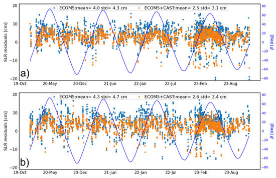
Figure 6.
The time series of SLR residuals for (a) C20 and (b) C21 satellites (the blue curve represents the variation of the angle).
In addition to the validations of the long-time orbit quality using SLR observations, we also assessed possible variation in orbit SRP accelerations using ABW [9], the semi-analytical model, which has the physical interpretation of SRP force. It is worth mentioning that the ABW model introduces empirical parameters, which correlate with the estimated optical coefficients. Thus, parameter resolution using the ABW model depends to some extent on prior satellite fundamental parameters and reasonable constraints, while ABW could output the total SRP accelerations, and offers a feasible method for quantitatively evaluating the degradation of SRP perturbation over time in orbit.
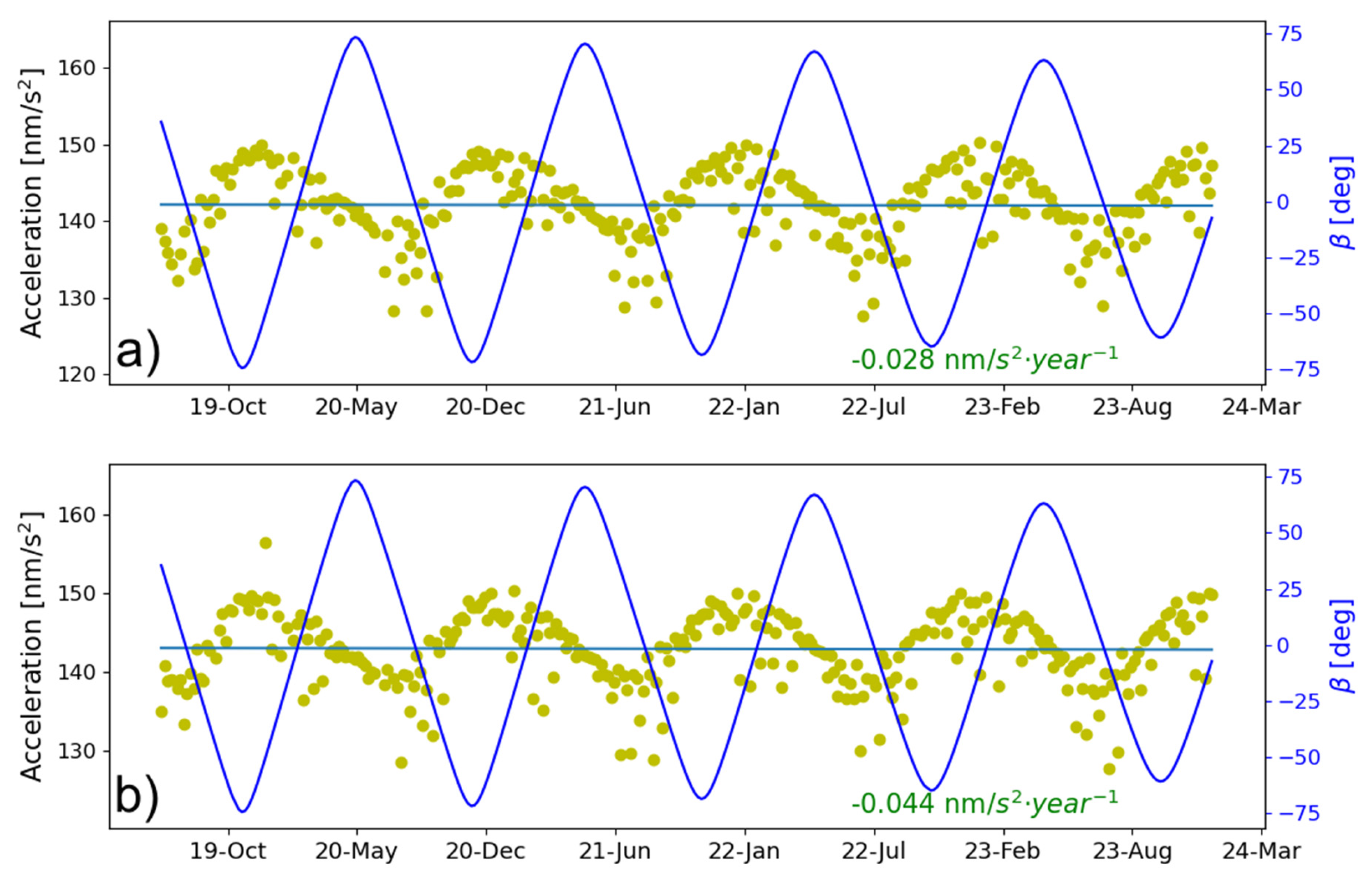
The total SRP accelerations output by ABW for C20 and C21 are shown in Figure 7. As can be seen, there is no apparent variation in SRP accelerations, where the slope is as much as 0.05 nm/s2, which could accumulate to 1% of the total SRP accelerations in more than 20 years. This could ensure that the output SRP acceleration based on the engineering data and the constructed priori SRP model can achieve a satisfactory orbit determination accuracy without considering the time-varying effect in the priori SRP model. It is consistent with the results that there is no orbit accuracy degradation as validated in Figure 6. It is noteworthy that, compared to the rather slow long-term variation rate of SRP perturbations, fluctuations within a single orbit period are more significant, reaching magnitudes of nearly 10 nm/s2. This is due to the varying solar illumination on the satellite surfaces under the different angle, especially the differences in duration on the +Z and +X panels, differences in optical properties, and the illuminated area of over 0.5 m2 as listed in Table 2.
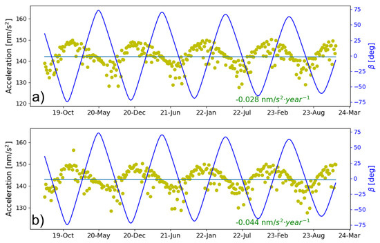
Figure 7.
A time series of the total SRP acceleration output by the ABW for satellites (a) C20 and (b) C21 (the blue curve represents the variation of the angle).
4. Discussion
By augmenting the ECOM with the proposed priori SRP model constructed for BDS-3 CAST MEO satellites, notably improved orbit solutions are obtained. The validations showed that the improved orbit accuracy in addition to the removal of the -angle dependent orbit errors is revealed by SLR residuals. An increased contribution of the orbit dynamical modeling will not only enable more accurate orbit solutions, but also improve the stability of the realization of reference frames. Actually, the reconstructed SRP model is convertible to the physical macro SRP model established with the available information on satellite dimensions, mass, and optical properties, while the model in truncated Fourier forms is superior when utilizing in practice, which is also performed for the GSPM series models developed at the JPL GNSS team [40,41]. Therefore, although the analytical SRP model was constructed based on the pre-launch measured data, the influence of time-varying optical parameters on SRP might be reasonably disregarded. Hence, we further investigate the total SRP acceleration by the semi-analytical ABW model due to the fact that the actual SRP accelerations can be hardly measured unless the detailed telemetry data targeting the on-orbit status and properties was accomplished and made available.
The ABW model, however, making use of both ground tracking data and the physical interpretation of the SRP force, can be used to evaluate the changes in total SRP accelerations and thus assess the usability of the proposed SRP model without considering a time-varying effect if the SRP acceleration stays stable over a long time period. One might argue that the ABW model introduces empirical parameters, which would correlate with the estimated optical coefficients. The optical parameters are the calibration of satellite surface optical coefficients using the ABW model that will inevitably be affected from the perspective of parameter estimation, while ABW could output the total SRP accelerations, and offers a feasible method for quantitatively evaluating the degradation of SRP perturbation over time in orbit.
On the other hand, the metadata is the vital foundation for the refinement of the observation model and dynamic model for the POD of BDS satellites. The optical properties can be calibrated by ground tracking data, which the semi-analytical SRP model somewhat depends on through how strong the constraints are applied for each parameter. Furthermore, if the a priori information from the metadata is incorrect, the adjusted optical properties have no physical meaning.
The ECOM2 model developed at the CODE has been predominantly used within the IGS community nowadays, in which the 7-parameter version (two additional one-order cosine and sine terms in the D direction apart from the 5 parameters in ECOM1) is reported to be beneficial to deal with satellites with a stretched body [8]. The concern might be raised on the comparison between the ECOM5+CAST and ECOM2 solutions and one-month data from DOY 200–230, 2023 is processed on this regard. The validations indicate that the solution enhanced by the proposed SRP model still shows an improved performance compared to the 7-prarater ECOM2 solution, in which the latter accounts for the elongated satellite body shape and makes positive corrections in reducing systematic orbit errors related to the angle revealed by SLR residuals. As to the OBDs, the ECOM5+CAST solution shows a slight advantage of about 5% with mostly in the along-track direction (see Supplementary Materials).
Further efforts could be made on the evaluation of SRP parameters, which will result in potential deviations caused by on-orbit degradation or surface material heterogeneity with other BDS-3 satellites along with the inclusion of the additional modeling and shadowing effect of the payload like the SAR antenna, in particular for the GEOs and IGSOs as it is more challenging to accurately model the orbit dynamic perturbations. Further analysis of the station coordinates, the Earth Rotations Parameters and some other geodetic parameters, could be performed as those parameters are probably correlated with the SRP model used. Furthermore, a noticeable different orbit performance revealed by SLR residuals indicates a quite different pattern for the two sets of BDS-3 CAST MEOs with a SAR antenna, i.e., C32–C33 and C45–C46. This might be attributed to another payload onboard like the telemetry antenna or other unmodelled orbit errors, and this needs further investigation.
5. Conclusions
In this study, we reconstructed an SRP model based on satellite engineering data for BDS-3 MEOs manufactured by the China Academy of Space Technology. In order to mitigate potential discrepancies between the analytical model and the actual SRP status, this model was utilized combined with the ECOM5 model. The SLR validations demonstrated that the model not only reduced bias in SLR residuals but also improved orbit accuracy, with the mean and standard deviation decreasing by approximately 38% and 27%, respectively, achieving an orbit accuracy in a radial direction of about 3–4 cm from 2019 to 2023. Moreover, it significantly mitigated systematic errors related to the angle compared to the purely 5-parameter ECOM orbit solution.
To further evaluate the usability and reliability of the proposed model, the orbit quality and evolution of the SRP acceleration generated by ABW based on a time series from over 5 years was studied. The results revealed that the variation of the total SRP acceleration is below 0.05 nm/s2 a year, which proved the reliability and usability of the proposed SRP model for BDS-3 CAST MEO satellites.
Supplementary Materials
The following supporting information can be downloaded at https://www.mdpi.com/article/10.3390/rs17061068/s1.
Author Contributions
Conceptualization, Q.C., C.W. and X.Z. (Xu Zhang); methodology, X.Z. (Xu Zhang) and C.W.; software, Q.C. and C.W.; validation, C.W. and C.R.; formal analysis, Q.C. and C.W.; writing—original draft preparation, Q.C. and C.W.; review and editing, Q.C., F.M., H.W. and X.Z. (Xinglong Zhao); funding acquisition, Q.C. and C.W. All authors have read and agreed to the published version of the manuscript.
Funding
This research was funded by the National Key R&D Program (2023YFC3008402), the National Natural Science Foundation of China (42304025), the China Postdoctoral Science Foundation (Grant No. 2022M710478), and the Fundamental Research Funds for the Central Universities (CHD 300102264202).
Data Availability Statement
The IGS observations can be accessed from IGS data centers, e.g., ftp://igs.gnsswhu.cn/pub/gps/data/daily/, accessed on 15 March 2025, and the iGMAS data used in this study are from iGMAS data centers. Those data are collected and managed by the iGMAS operation command and control center and can be made available with the permission by CSNO. The SLR normal point data are available from ILRS data center.
Acknowledgments
The iGMAS, IGS, and ILRS are greatly acknowledged for providing the Multi-GNSS data and SLR measurements. The numerical calculations reported in this paper were performed using the high-performance computing platform of Chang’an University.
Conflicts of Interest
The authors declare no conflicts of interest.
Abbreviations
The following abbreviations are used in this manuscript:
| ABW | Adjustable Box-Wing model |
| CAST | China Academy of Space Technology |
| CSNO | China Satellite Navigation Office |
| GNSS | Global Satellite Navigation System |
| iGMAS | International GNSS Monitoring and Assessment System |
| IGS | The International GNSS service |
| ILRS | International laser ranging service |
| LRA | Laser Ranging Array |
| MEO | medium earth orbit |
| POD | Precise orbit determination |
| SAR | Search and Rescue |
| SLR | Satellite laser ranging |
| SRP | Solar radiation pressure |
| SECM | Shanghai Engineering Center for Microsatellites |
References
- Yang, Y.; Mao, Y.; Sun, B. Basic performance and future developments of BeiDou global navigation satellite system. Satell. Navig. 2020, 1, 1. [Google Scholar] [CrossRef]
- Zhao, Q.; Guo, J.; Wang, C.; Lyu, Y.; Xu, X.; Yang, C.; Li, J. Precise orbit determination for BDS satellites. Satell. Navig. 2022, 3, 2. [Google Scholar] [CrossRef]
- Fligel, H.F.; Gallini, T.E.; Swift, E.R. Global positioning system radial force model for geodetic applications. J. Geophys. Res. 1992, 97, 559–568. [Google Scholar] [CrossRef]
- Fliegel, H.F.; Gallini, T.E. Solar force modeling of block IIR Global Positioning System satellites. J. Spacecr. Rocket. 1996, 33, 863–866. [Google Scholar] [CrossRef]
- Ziebart, M. High Precision Analytical Solar Radiation Pressure Modelling for GNSS Spacecraft. Ph.D. Thesis, University College London (UCL), London, UK, 2001. [Google Scholar]
- Beutler, G.; Brockmann, E.; Gurtner, W.; Hugentobler, U.; Mervart, L.; Rothacher, M.; Verdun, A. Extended orbit modeling techniques at the CODE processing center of the international GPS service for geodynamics (IGS): Theory and initial results. Eur. Respir. J. 1994, 7, 1350–1364. [Google Scholar] [CrossRef]
- Springer, T.A.; Beulter, G.; Rothacher, M. A new solar radiation pressure model for GPS satellites. GPS Solut. 1999, 2, 50–62. [Google Scholar] [CrossRef]
- Arnold, D.; Meindl, M.; Beutler, G.; Dach, R.; Schaer, S.; Lutz, S.; Prange, L.; Sośnica, K.; Mervart, L.; Jäggi, A. CODE’s new solar radiation pressure model for GNSS orbit determination. J. Geod. 2015, 89, 775–791. [Google Scholar] [CrossRef]
- Rodriguez-Solano, C.J.; Hugentobler, U.; Steigenberger, P. Adjustable box-wing model for solar radiation pressure impacting GPS satellites. Adv. Space Res. 2012, 49, 1113–1128. [Google Scholar] [CrossRef]
- Guo, J. The Impacts of Attitude, Solar Radiation and Function Model on Precise Orbit Determination for GNSS Satellites. Ph.D. Thesis, GNSS Research Center, Wuhan University, Wuhan, China, 2014. (In Chinese). [Google Scholar]
- Wang, C.; Guo, J.; Zhao, Q.; Liu, J. Yaw attitude modeling for BeiDou I06 and BeiDou-3 satellites. GPS Solut. 2018, 22, 117. [Google Scholar] [CrossRef]
- Yan, X.; Liu, C.; Huang, G.; Zhang, Q.; Wang, L.; Qin, Z.; Xie, S. A priori solar radiation pressure model for BeiDou-3 MEO satellites. Remote Sens. 2019, 11, 1605. [Google Scholar] [CrossRef]
- Sosnica, K.; Zajdel, R.; Bury, G.; Bosy, J.; Moore, M.; Masoumi, S. Assessment of experimental IGS multi-GNSS combined orbits. GPS Solut. 2020, 24, 54. [Google Scholar] [CrossRef]
- Guo, J.; Wang, L.; Yang, C.; Li, J.; Xu, X.; Zhao, Q. Modeling and comparison of solar radiation pressure for two BDS-3 MEO satellites (C45 and C46) with SAR payload. Adv. Space Res. 2024, 75, 1163–1176. [Google Scholar] [CrossRef]
- Wang, C. Solar Radiation Pressure Modelling for BeiDou Navigation Satellites. Ph.D. Thesis, Wuhan University, Wuhan, China, 2019. (In Chinese). [Google Scholar]
- Li, X.; Yuan, Y.; Zhu, Y.; Jiao, W.; Bian, L.; Li, X.; Zhang, K. Improving BDS-3 precise orbit determination for medium earth orbit satellites. GPS Solut. 2020, 24, 53. [Google Scholar] [CrossRef]
- Duan, B.; Hugentobler, U.; Selmke, I.; Marz, S.; Killian, M.; Rott, M. BeiDou Satellite Radiation Force Models for Precise Orbit Determination and Geodetic Applications. IEEE Trans. Aerosp. Electron. Syst. 2022, 58, 2823–2836. [Google Scholar] [CrossRef]
- Liu, J.; Gu, D.; Ju, B.; Shen, Z.; Lai, Y.; Yi, D. A new empirical solar radiation pressure model for BeiDou GEO satellites. Adv. Space Res. 2016, 57, 234–244. [Google Scholar] [CrossRef]
- Chen, X.; Ge, M.; Liu, Y.; He, L.; Schuh, H. Adapting empirical solar radiation pressure model for BDS-3 medium Earth orbit satellites. GPS Solut. 2023, 27, 183. [Google Scholar] [CrossRef]
- Prange, L.; Villiger, A.; Sidorov, D.; Schaer, S.; Beutler, G.; Dach, R.; Jäggi, A. Overview of CODE’s MGEX solution with the focus on Galileo. Adv. Space Res. 2020, 66, 2786–2798. [Google Scholar] [CrossRef]
- Tan, B.; Yuan, Y.; Zhang, B.; Hsu, H.; Ou, J. A new analytical solar radiation pressure model for current BeiDou satellites: IGGBSPM. Sci. Rep. 2016, 6, 32967. [Google Scholar] [CrossRef]
- Duan, B.; Hugentobler, U.; Selmke, I. The Adjusted Optical Properties for Galileo/BeiDou-2/QZS-1 Satellites and Initial Results on BeiDou-3e and QZS-2 satellites. Adv. Space Res. 2018, 63, 1803–1812. [Google Scholar] [CrossRef]
- Shi, C.; Xiao, Y.; Fan, L.; Zheng, F.; Wang, C.; Huang, Z.; Li, Z. Research progress of radiation pressure modelling for navigation satellites. Acta Aeronaut. Astronaut. Sin. 2022, 43, 527389. [Google Scholar]
- Chen, Q.; Chen, Z.; Wang, H. Modeling and Analysis of Solar Radiation Pressure for GPS Satellites. Spacecr. Eng. 2013, 22, 27–32. [Google Scholar] [CrossRef]
- China Satellite Navigation Office. Satellite Information of BDS. 2019. Available online: http://en.beidou.gov.cn/SYSTEMS/Officialdocument/ (accessed on 1 February 2025).
- Montenbruck, O.; Schmid, R.; Steigenberger, P. GNSS Satellite Geometry and Attitude Models. Adv. Space Res. 2015, 56, 1015–1029. [Google Scholar] [CrossRef]
- Johnston, G.; Riddell, A.; Hausler, G. The International GNSS Service. In Springer Handbook of Global Navigation Satellite Systems; Teunissen, P.J.G., Montenbruck, O., Eds.; Springer International Publishing: Cham, Switzerland, 2017; pp. 967–982. [Google Scholar]
- Huang, W. Effect of Earth Infrared Radiation on Infrared Temperature Measurement for Exoatmospheric Objects. Opto-Electron. Eng. 2009, 36, 34. [Google Scholar]
- Rodriguez-Solano, C.J.; Hugentobler, U.; Steigenberger, P.; Lutz, S. Impact of Earth radiation pressure on GPS position estimates. J. Geod. 2011, 86, 309–317. [Google Scholar] [CrossRef]
- Flett, R.M. Passive Temperature Control in Space Environment; National Defense Industry Press: Beijing, China, 1975; pp. 42–43. [Google Scholar]
- Rim, H.; Webb, C.E.; Yoon, S.; Schutz, B.E. Radiation Pressure Modeling for ICESat Precision Orbit Determination. In Proceedings of the AIAA/AAS Astrodynamics Specialist Conference and Exhibit, Keystone, CO, USA, 21–24 August 2006; pp. 21–24. [Google Scholar]
- Jiao, W.; Ding, Q.; Li, J.; Lu, X.; Feng, L.; Ma, J.; Chen, G. Monitoring and assessment of GNSS open services. J. Navig. 2011, 64 (Suppl. S1), S19–S29. [Google Scholar] [CrossRef]
- Liu, J.; Ge, M. PANDA software and its preliminary result of positioning and orbit determination. Wuhan Univ. J. Nat. Sci. 2003, 8, 603–609. [Google Scholar] [CrossRef]
- Standish, E.M. JPL Planetary and Lunar Ephemerides. DE405/LE405, JPL IOM 312.F-98-048. 1998. Available online: https://ssd.jpl.nasa.gov/planets/eph_export.html (accessed on 1 February 2025).
- Boehm, J.; Niell, A.; Tregoning, P.; Schuh, H. Global Mapping Function (GMF): A new empirical mapping function based on numerical weather model data. Geophys. Res. Lett. 2006, 33, L07304. [Google Scholar] [CrossRef]
- Wu, J.; Wu, S.; Hajj, G.; Bertiger, W.; Lichten, S. Effects of antenna orientation on GPS carrier phase. Manuscr. Geod. 1993, 18, 91–98. [Google Scholar] [CrossRef]
- Ge, M.; Gendt, G.; Dick, G.; Zhang, F.P. Improving carrier-phase ambiguity resolution in global GPS network solutions. J. Geod. 2005, 79, 103–110. [Google Scholar] [CrossRef]
- Pearlman, M.R.; Noll, C.E.; Pavlis, E.C.; Lemoine, F.G.; Combrink, L.; Degnan, J.J.; Kirchner, G.; Schreiber, U. The ILRS: Approaching 20 years and planning for the future. J. Geod. 2019, 93, 2161–2180. [Google Scholar] [CrossRef]
- Montenbruck, O.; Steigenberger, P.; Hugentobler, U. Enhanced solar radiation pressure modeling for Galileo satellites. J. Geod. 2015, 89, 283–297. [Google Scholar] [CrossRef]
- Bar-Sever, Y.; Kuang, D. New Empirically-Derived Solar Radiation Pressure Model for GPS Satellites; Technical Report; IPN Progress Report; JPL: La Cañada Flintridge, CA, USA, 2004; pp. 42–159. Available online: https://ipnpr.jpl.nasa.gov/progress_report/42-159/159I.pdf (accessed on 1 February 2025).
- Sibois, A.; Selle, C.; Desai, S.; Sibthorpe, A.; Weiss, J. GSPM13: An updated empirical model for solar radiation pressure forces acting on GPS satellites. In Proceedings of the IGS Workshop 2014, Pasadena, CA, USA, 23–27 June 2014. [Google Scholar]

Disclaimer/Publisher’s Note: The statements, opinions and data contained in all publications are solely those of the individual author(s) and contributor(s) and not of MDPI and/or the editor(s). MDPI and/or the editor(s) disclaim responsibility for any injury to people or property resulting from any ideas, methods, instructions or products referred to in the content. |
© 2025 by the authors. Licensee MDPI, Basel, Switzerland. This article is an open access article distributed under the terms and conditions of the Creative Commons Attribution (CC BY) license (https://creativecommons.org/licenses/by/4.0/).