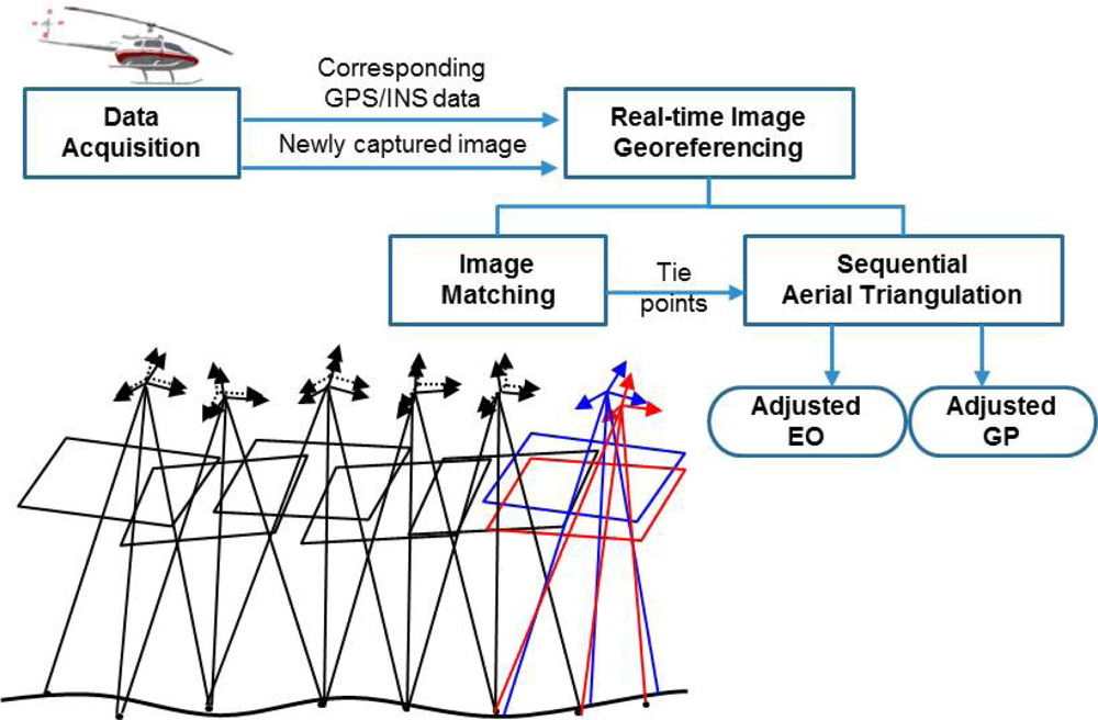
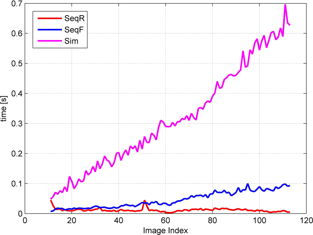
Under these assumptions, we have to perform aerial triangulation in real time for real-time image georeferencing. Aerial triangulation is a sequential estimation problem where we have to update existing parameters whenever new observations and even new parameters are added. Therefore, we propose a sequential aerial triangulation approach in which we will not only estimate the camera parameters of the new images, but also update those of the existing images whenever a new image is added.
During real-time image acquisition, a new image is continuously being added into an image sequence. The addition of an image involves the addition of the following new parameters: six extrinsic parameters of the camera, also called the exterior orientation parameters (EOP), and 3n parameters for the ground point coordinates corresponding to n pairs of the new tie points. The traditional simultaneous AT algorithm estimates the existing and new parameters using the existing and new observations based on a grand adjustment process, and ignores any computation results from the previous stage. As the number of images increases, this process requires much more time and memory for computation, preventing real-time processing. In order to perform georeferencing of an image sequence in real time, we use a sequential AT approach equipped with an efficient update formula that can minimize the amount of computation at the current stage by using the computation results from the previous stage.
2.1. The Initial Stage
In the initial stage, a small number of images are acquired, and the traditional simultaneous aerial triangulation algorithms based on bundle block adjustment is applied. Here, the EOP of the images and the coordinates of ground points (GP) corresponding to the tie points are the parameters to be estimated. The collinearity equations for all the tie points are used as the observation equations. The initial EOP provided from the GPS/INS system is used for stochastic constraints. The observation equations with the stochastic constraints can be expressed as
where
ξe1 and
ξp1 are the parameter vectors for the EOP and GP, respectively;
y11 is the observation vector for the tie points;
Ae11 and
Ap11 are the design matrices derived from the partial differentiation of the collinearity equations corresponding to the tie points with respect to the parameters,
ξe1 and
ξp1;
z1 is the observation vector of the EOP provided by the GPS/INS system;
K1 is the design matrix associated constraints, expressed as an identity matrix;
ey11 and
ez1 are the error vectors associated with the corresponding observation vectors;
is the unknown variance component;
is the cofactor matrix of
ey11, generally expressed as an identity matrix; and
is the cofactor matrix of
ez1, reflecting the precision of the GPS/INS.
The observation equations can be rewritten as
where
By applying the least squares principle, we can derive the normal equations as follows:
where
With the sub-block representations of the normal matrix and the right side, the normal equation can be rewritten as
where
The inverse of the normal matrix is then represented as
where
;
;
; and
.
For this computation, we need to calculate the inverses of the matrices,
Np11 and
Nr1. The computation of
is efficient because it is a 3 × 3 block diagonal matrix, and the computation of
is also efficient because it is a band-matrix. This is a well-known property of the bundle block adjustment method. Therefore, the parameter estimate can be computed as
2.2. The Sequential Combined Stage
With the results of the initial stage, we can progress toward the combined stage. At the combined stage, we have a set of new images and the newly identified ground points corresponding to the tie points either in new images only or in new and existing images together. The parameter vectors for the EOP of the new images and the newly identified ground point coordinates are denoted as
ξe2 and
ξp2, respectively. In addition, we also have two kinds of new observations. One set of observations is related to both existing and new parameters, and the other set of observations is related to only new parameters. The observation equations corresponding to the first set are expressed as shown in
Equation (7), and the observation equations corresponding to the second set are expressed as
Equation (8).
where
y12 is the observation vector for the image points in the existing images for newly identified GPs;
y21 is the observation vector for the image points in the new images for previously identified GPs;
Ae12 and
Ap12 are the design matrices derived from the partial differentiation of the collinearity equations corresponding to the image points related to
y12 with respect to the parameters,
ξe1 and
ξp2;
Ap21 and
Ae21 are the design matrices derived from the partial differentiation of the collinear equations corresponding to the image points related to
y21 with respect to the parameters,
ξp1 and
ξe2;
ey12 and
ey21 are the error vectors associated with the corresponding observation vectors;
and
are the cofactor matrix of
ey12 and
ey21, generally expressed as an identity matrix.
where
y22 is the observation vector for the image points in the new images for newly identified GPs;
Ae22 and
Ap22 are the design matrices derived from the partial differentiation of the collinear equations corresponding to the image points related to
y22 with respect to the parameters,
ξe2 and
ξp2;
z2 is the observation vector about the EOP of the new images, provided by the GPS/INS system;
K2 is the design matrix associated with the constraints, expressed as an identity matrix;
ey22 and
ez2 are the error vectors associated with the corresponding observation vectors;
is the cofactor matrix of
ey22, generally expressed as an identity matrix; and
is the cofactor matrix of
ez2, reflecting the precision of the GPS/INS system.
The new observation equations in
Equations (7) and
(8) are combined with the existing observation equations in
Equation (1) to estimate the parameters at the combined stage. The entire combined observation equations are then expressed as
where
The normal equations resulting from the application of the least squares principle to the observation equations are expressed as
where
;
;
;
;
;
;
;
; and
.
During an estimation process based on the least squares principle, the most time-consuming step is the computation of the inverse of the normal matrix. Since the size of the normal matrix is the sum of the number of existing and new parameters (n1 + n2), it gradually increases while new images are repeatedly acquired. Although we have to estimate all the parameters whenever a new image is acquired, after a significant number of images are acquired, we cannot compute the inverse of the normal matrix within the required time period since the size of the normal matrix is too large. This requires the derivation of an update formula in order to efficiently compute the inverse of the normal matrix using the results computed at a previous stage.
The inverse of the normal matrix can be written as
where
;
W1 =
M12(
M22 +
L22)
−1;
and
, using an inversion formula of a block matrix,
where
R ≡
A −
BD−1C.
The main component in the inverse of the normal matrix is
. This can be computed as
where
, using
Since we already computed
in the previous stage, we will only compute
and (
M22 +
L22)
−1 in
P̄2. Using these derivations, we can efficiently compute the inverse of the normal matrix in
Equation (11). Suppose that we have already had 150 images and 100 GPs, and a new image and 3 GPs have just been acquired. It should be noted that the size of the inverse normal matrix to be computed is (
n1 +
n2), where
n1 is the number of existing parameters, (150 × 6) + (100 × 3) = 1200, and
n2 is the number of new parameters, (1 × 6) + (3 × 3) = 15. Although we employ a reduced normal matrix scheme, we have to compute a large inverse matrix. The dimension of one matrix is (151 × 6) = 906, depending on the total number of images. This number grows during image acquisition and eventually it is impossible to compute the inverse of the normal matrix within the maximum time period allowed for real-time georeferencing, which is normally less than the image acquisition period.
Such a situation can be relieved by using an efficient sequential update formula derived from
Equations (11) and
(12). Assume that one GP among three new GPs appears on the previous three images and eight GPs among the existing 100 GPs appear on the new image. Using our sequential formula, we should compute two inverse matrices,
and (
M22 +
L22). The size of the first one is
n12 +
n21, where
n12 is the number of observations corresponding to new GPs appearing on previous images, ((1 × 3) × 2) = 6, and
n21 is the number of observations corresponding to existing GPs emerging on new images, ((8 × 1) × 2) = 16. Furthermore, the size of the second one is
np2 ×
ne2, where
np2 is the number of observations corresponding to new GPs only appearing on new images, ((2 × 1) × 2) = 4, and
ne2 is the number of EOPs of the new images, (1 × 6) = 6. Hence, instead of computing an inverse of a matrix with a size of 906, we can estimate the same parameters by computing only the inverses of two matrices, the sizes of which are 22 and 10, using our sequential formula. This numerical example indicates our algorithm’s computational efficiency and is practical for real-time applications. The estimates for the existing parameter vector can be expressed as the estimates at the previous stage
ξ̂1. It is updated for the current stage, as shown in
Equation (13). The estimates for the new parameter vector
can be derived according to
Equation (14).
2.3. The Sequential AT with Highly Correlated Images
The number of parameters to be updated increases linearly whenever a new image is added into an image sequence, although we use the computation results from the previous stage to efficiently compute the inverse of the normal matrix at the current stage. If we have to acquire an image sequence for a long time, it would be impossible to perform AT in real time due to the extremely large size of the parameter vector. We thus need to maintain a constant parameter vector size for real-time processing. For this purpose, we may update the parameters associated with a certain number of recent images, for example, the latest 50 images. However, such a constant number is set by intuition; it does not originate from the underlying principle of the estimation process. In this study, the correlation between parameters is employed to reasonably limit the size of the parameter vector. It is obvious that some images in the beginning of the sequence must have almost no correlation with a new image if image acquisition continues for a long time. Therefore, we do not update the parameters associated with the images in the beginning of the sequence in such a case. To exclude parameters associated with the images in the beginning of the sequence, we determine the correlation coefficient between the parameters of the current stage and those of the previous stage. If the correlation coefficients between the previous parameters and current parameters are larger than a threshold, only the previous parameters should be updated.
The correlation coefficient is an efficient measure of the correlation between two variables. In general, the correlation coefficient between two variables can be computed using the covariance between the two variables and the standard deviation of each variable. A variance-covariance matrix, derived from an adjustment computation, consists of the variance of a parameter and the covariance between parameters. Our sequential AT process not only estimates the parameters, EOP and GP, but also offers a cofactor matrix (Q) including the variance of the estimated EOP/GP and the covariance between the estimated EOP/GP at every stage. In our proposed algorithm, as shown in
Equation (12), the cofactor matrix can be efficiently updated at every stage and is thus actually ready to use without further matrix operations. The diagonal element of the Q matrix is the variance, indicating the dispersion of the estimated EOP/GP, while the remaining off-diagonal element is the covariance, indicating the correlations between the estimated EOP/GP. Consequently, we can quickly calculate the correlation coefficient between parameters using the standard deviation, which is the square root of the diagonal elements and the covariance from the cofactor matrix.
We have two classes of parameters,
i.e., EOPs of each image and GPs corresponding to all the tie points. The parameters to be updated are selected separately from among previous parameters as a class. First, we select previous EOPs that are highly correlated with the EOPs of a new image by determining the correlation coefficient between EOPs. However, a problem arises because the correlation coefficient between the existing EOPs and the EOPs of a new image can be found only after adjusting for both existing parameters and new parameters. It is inefficient to adjust all previous parameters without excluding those that correlate poorly with new parameters. It is apparent that a new image is likely to be closest to the last image of the previous set, so we use the correlation coefficient between the EOPs of the previous images and the EOPs of the last image of the previous set instead of the EOPs of the new image. As shown in
Figure 2, the last image (blue) instead of the new image (red) is employed to compute the correlation coefficient of the previous images. The EOPs of the image, whose correlation coefficients with the EOPs of the last image are less than a threshold, are excluded from the parameter vector to be updated. Each EOP set of two images has six parameters,
X,
Y,
Z,
ω,
ϕ, and
κ, referring to the position and attitude of the camera. Therefore, the correlation coefficients between the EOPs of the two images are presented as a 6 × 6 matrix. The maximum value among those 36 components in the correlation coefficient block is considered the correlation coefficient between the EOPs of the two images.
To facilitate the efficient implementation of this algorithm, there is no further examination of the correlation coefficient between the EOPs of the next images and the EOPs of the last image after an image highly correlated with the last image is detected from the beginning of the sequence. For example, if the correlation coefficient between the EOPs of the third image and those of the last image is more than the threshold for the first time, all of the EOPs from the third image to the last image should be updated, even though the correlation coefficient of the EOPs for the fifth and the last image is less than the threshold (
Figure 2).
After the images associated with the EOPs included in the adjustment are selected, GPs appearing only in the images associated with EOPs excluded from the adjustment also have to be eliminated in the adjustment computation. Some GPs may appear only once in the images associated with the EOPs included in the adjustment. They should also be deleted from the adjustment computation because they can no longer be considered to be derived from tie points. As shown in
Figure 2, white GPs do not appear or appear only once in the images associated with the EOPs included in the adjustment. Therefore, those white GPs are excluded from the parameter vector to be updated. Finally, the EOPs and GPs that are highly correlated with a new image are determined and the size of the parameter vector can be held nearly constant. The algorithm for keeping constant the parameter vector size is summarized below.
| Do if a new image is acquired |
| For n = 1: the number of previous images |
| Calculate the correlation coefficient between EOPs of a previous image and the new image. |
| If (the correlation coefficient < a threshold) |
| Exclude the EOPs of a previous image from the parameter vector. |
| Else |
| Count the number of images that appear per previous GP |
| If (the appearance number > 1) |
| Include the GP in the parameter vector |
