
Crosstalk Effect in SNPP VIIRS


1
NOAA National Environmental Satellite, Data, and Information Service, Center for Satellite Applications and Research, E/RA3, 5830 University Research Ct., College Park, MD 20740, USA
2
Global Science and Technology, 7855 Walker Drive, Suite 200, Greenbelt, MD 20770, USA
*
Author to whom correspondence should be addressed.
Remote Sens. 2017, 9(4), 344; https://doi.org/10.3390/rs9040344
Submission received: 6 February 2017
/
Revised: 21 March 2017
/
Accepted: 1 April 2017
/
Published: 4 April 2017
Abstract
:An investigation has been carried out to examine the crosstalk contamination in the Visible Infrared Imaging Radiometer Suite (VIIRS) onboard the Suomi National Polar-orbiting Partnership (SNPP) spacecraft. Prior to this study, the cause of the pronounced striping in Earth View (EV) images and obvious discontinuity in the EV brightness temperature (BT) of the thermal emissive bands (TEB) during black body (BB) warm-up cool-down (WUCD) calibration observed since launch has not been identified. Meanwhile, it has been recently demonstrated in the MODerate-resolution Imaging Spectroradiometer (MODIS) long-wave infrared (LWIR) photovoltaic (PV) bands that the crosstalk effect induces the same erroneous features. In this investigation, it is shown that the established lunar imagery analysis indeed verifies the existence of crosstalk contamination in SNPP VIIRS TEB. The crosstalk effect is quantitatively characterized by deriving the crosstalk coefficients from the scheduled lunar observations. The magnitude of the effect is comparatively smaller than that in MODIS LWIR PV bands, but is of a large enough magnitude to induce the aforementioned artificial features. Among all SNPP VIIRS TEB, Band M14 has the largest crosstalk contamination from Band M15, while Bands M13, M15, M16, and I5 have pronounced crosstalk effects as well. One new detail of the crosstalk effect specific to SNPP VIIRS, differing from the MODIS result, is the distinctive two-group pattern of odd and even detectors for each affected band due to the arrangement of the detector on the focal plane assembly (FPA). This is fully consistent with the earlier finding that this odd-even detector arrangement contributes to striping in the sea surface temperature (SST) products. Our analyses additionally suggest an explanation of the large temperature anomalies appearing during the WUCD time periods. The parallel effort examining the potential crosstalk contamination in SNPP VIIRS reflective solar bands, however, reveals no observable effect.
1. Introduction
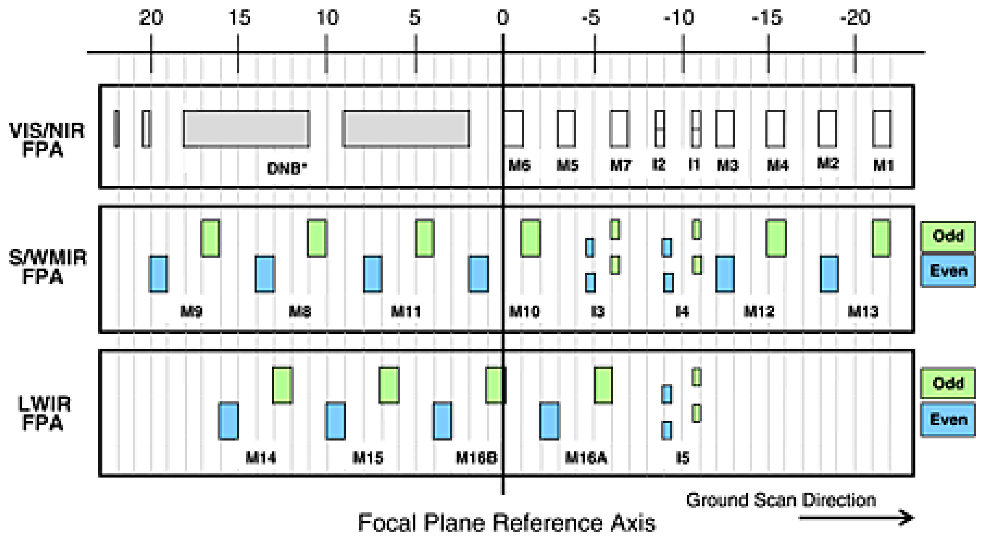
The Visible Infrared Imaging Radiometer Suite (VIIRS) onboard the Suomi National Polar-orbiting Partnership (SNPP) satellite was launched on 28 October 2011 [1,2]. VIIRS has 22 spectral bands covering a spectral range from 0.410–12.013 µm, which includes 14 reflective solar bands (RSB), 7 thermal emissive bands (TEB), and a panchromatic day/night band (DNB). Among the RSB and TEB, 5 are imaging bands (I-bands) with higher spatial resolution while the other 16 are moderate resolution bands (M-bands). Among the 16 M-bands, 7 are dual-gain bands while the other M-bands as well as all 5 I-bands are single-gain bands. The central wavelengths of the 22 SNPP VIIRS bands, their center wavelengths, key specifications, and major applications are listed in Table 1 [3]. These 22 bands are distributed on three focal plane assemblies (FPA) as displayed in Figure 1. They are calibrated on-orbit either with an on-board solar diffuser (SD) and SD stability monitor (SDSM) system for RSB [4,5,6,7,8,9,10,11] or with an onboard blackbody (BB) for TEB [12,13]. The Moon, which is scheduled to be viewed approximately monthly through the instrument’s space view (SV) port [14,15,16], and the Earth targets are also used to monitor the radiometric performance. VIIRS views the SV, Earth view (EV), BB, and SD, respectively, via a rotating telescope assembly (RTA) and half-angle mirror (HAM). The SNPP VIIRS has successfully provided the sensor data records (SDR) for more than twenty environmental data records (EDR) including clouds, sea surface temperature, ocean color, polar wind, vegetation fraction, aerosol, fire, snow and ice, vegetation, and other applications.
Since the beginning of the mission, significant scene-dependent striping has been seen in the EV imagery of both SNPP VIIRS RSB and TEB [17,18,19]. The empirical destriping algorithm has been developed [18] and implemented [19] into operations for the TEB to remove the striping in the EV brightness temperatures (BT) by the National Oceanic and Atmospheric Administration (NOAA) Sea Surface Temperature (SST) Team. The methodology has also been adopted and applied later for the RSB to reduce the striping in ocean color products [20]. The striping can be induced by various causes such as detector-dependent relative spectral response (RSR) [21,22,23], crosstalk effect [24,25,26,27,28,29,30,31], and others. For RSB, the detector dependent polarization effect is another major cause for the striping in the imagery [32,33]. The potential induction of the striping in the TEB imagery by RSR errors has been investigated and discussed [21,22,23] but has not fully explained the striping in SNPP VIIRS TEB. This examination focuses on crosstalk contaminations as a physical cause of significant striping as well as other effects in the science products. A strong crosstalk effect was found in SNPP VIIRS during prelaunch measurements [34,35,36] for both the RSB and TEB. Great effort was spent to characterize the effect but the results were found to vary with the measurements, possibly due to contamination of the scattering light from the various resources. After the SNPP VIIRS launch, the lunar observations were used to check the crosstalk effect [15]. An early mission analysis basing also on lunar images surprisingly found that the RSB no longer exhibits the crosstalk effect while TEB still displays some visible effect weaker than expected [15]. This discrepancy between the prelaunch tests and on-orbit measurements was a pleasant turnout, but so far remains unexplained and requires further investigation. In this paper, we will concentrate on the crosstalk effect after the instrument launch since it directly impacts the science products as the current key issue of high interest.
It was reported from early missions that the SNPP VIIRS ocean SST shows sudden increase during the VIIRS BB warm-up cool-down (WUCD) calibration [37]. Several investigations including some preliminary efforts to improve and stabilize BB calibration [38,39] have been conducted, but the anomaly cannot be completely mitigated and a definitive connection to any root cause is still elusive. In fact, an early investigation showed that SNPP VIIRS has observable crosstalk contaminations in TEB as mentioned previously [15]. As numerous recent investigations into MODIS unambiguously demonstrate that the crosstalk effect can induce the aforementioned artifacts [24,25,26,27,28,29,30,31], the crosstalk effect must necessarily be an important contributor to the artifacts and anomalies known in SNPP VIIRS.
Crosstalk contaminations can be either electronic or optical in origin. Electronic crosstalk in a remote sensor is a phenomenon causing electronic signals to be induced into a particular band from the detectors of neighboring bands on the same FPA [24,25,26,27,28,29,30,31]. The electronic crosstalk effect induces unexpected sudden jumps, rapid changes, and strong detector differences in the calibration coefficients derived from BB calibration [24,25,26,27,28,29,30,31]. The level of contamination varies with the detector of the affected band as well as ones of the sending bands. The varying levels across different detectors then can induce striping in the imagery of the affected band. The striping caused by this contamination may be scene dependent [24,25,26,27,28,29,30,31] due to the varying signal level of the scenes. The effect may also become more severe with time, resulting in worsening bias and long-term drifts in the EV retrievals as has been demonstrated for the MODIS long wave infrared (LWIR) photo-voltaic (PV) bands [24,25,26,27,28,29,30,31]. It also induces a ghost image when a sharp edge exists in the observing target, due to the different locations of the receiving and sending bands on the focal plane, leading to images of the sharp edge of the sending band to appear as a ghost next to the corresponding image features of the receiving band. The optical crosstalk is induced by the light scattered from one channel to another after the light passes through the filters of the detectors. It induces the same artifacts as the electronic crosstalk except that its contribution to the signal is always positive while that of electronic crosstalk can be either positive or negative. It is worth drawing attention to the fact that the optical crosstalk does not include the effect of optical leak such as out-of-band (OOB) relative spectral response (RSR). Because it is hard to separate the electronic crosstalk and optical crosstalk, this analysis focuses on the combined effect of the two types of crosstalk effect as a whole. As mentioned above, both electronic and optical crosstalk induce a ghost image, and thus ghost image is an intrinsic feature of the crosstalk effect that can be used to characterize the effect. The Moon is a “point-like” target with a finite size and a clear edge [15,16,40] that can be used for such purposes. Since regularly scheduled observations of the moon occur approximately monthly, an analysis using these lunar images can be used to characterize the crosstalk effect and to derive the crosstalk coefficients for an affected band from the artificial structures around a lunar image observed by the band [24,25,26,27,28,29,30,31].
Sun et al. [24,25,26,27,28,29,30,31] have developed a linear model to describe the crosstalk effect and have shown a successful mitigation of the aforementioned artifacts in the MODIS LWIR PV bands. So far, there have been more than 40 regularly scheduled lunar observations for SNPP VIIRS since its launch [14,15,16]. In this paper, the results from the lunar imagery analysis will show that there are very clear crosstalk effects in most of the SNPP VIIRS TEB while no observable crosstalk effect is found in the RSB. The crosstalk effect for each contaminated TEB is characterized by identifying the sending bands and deriving the crosstalk coefficients, characterizing the effect of the affected band from the sending bands, by using the scheduled lunar observations. The details of the model, the characterization procedure of the crosstalk effect, and the mitigation results have been fully laid out in the references noted above.
The rest of the paper is organized as follows. In Section 2, the crosstalk effect signals are demonstrated using the lunar images for the affected TEB while also showing no effect in all RSB and a few TEB. In Section 3, the crosstalk correction methodology and the crosstalk characterization algorithm are briefly reviewed. In Section 4, the crosstalk coefficients are derived for the affected TEB from the scheduled lunar observations and the results are discussed. The crosstalk impacts on the affected bands are also discussed. Section 5 is a brief summary of this analysis.
2. Crosstalk Effect
For a remote sensor, the crosstalk effect can only occur among the bands on the same FPA. SNPP VIIRS has three FPAs—the visible and near-infrared (VIS/NIR) FPA, shortwave mid-infrared (SW/MIR) FPA, and long wave infrared (LWIR) FPA—as shown in Figure 1. Therefore, the SNPP VIIRS bands are classified into three separate groups in which the crosstalk contamination can only occur among bands within each group. Since different bands on the same FPA see the same target at different times, the crosstalk effect induces ghost images in the imagery and can be especially distinctive and pronounced when a sharp edge exists [24]. This unique and typical property of the crosstalk can be used to identify and characterize the crosstalk contamination. As mentioned previously and shown in our previous work [24,25,26,27,28,29,30,31], the Moon is a proper target for crosstalk effect identification and characterization given its clear imagery with a sharp edge. In this section, we will identify and quantify the crosstalk effect in SNPP VIIRS using the regularly scheduled lunar observations [14,15,16].
VIIRS views the Moon through its SV. For a scheduled lunar observation, the instrument signals are stored in the EV data sector through a sector rotation, in which the lunar image is located at the center of the sector. For the VIIRS EV sector, an along-scan sample aggregation has been applied to reduce the number of “pixels” along the scan direction while keeping the pixel size on the Earth surface about the same along the scan [3]. The aggregation is performed on board for single-gain bands, while the dual-gain M-bands are transmitted unaggregated, leaving the aggregation to be performed during ground processing following radiometric calibration of the individual samples. The data used in this analysis are the data before radiometric calibration and thus the aggregation scheme has not yet been applied to the dual-gain bands [3]. Since the lunar images are located in the center of the sector, the “pixel” widths along the scan for the I-bands, dual-gain M-bands, and single-gain M-bands are 0.387 km, 0.259 km, and 0.776 km, respectively, as listed in Table 1. The Moon radius spans 7 pixels of a 1-km band, and corresponds to about 18, 27, and 9 pixels for the I-bands, dual-gain M-bands, and single-gain M-bands, respectively [40]. Due to the so-called oversampling effect [40], the whole Moon is viewed by each individual detector in any of the VIIRS bands. Also because of the effect, the obtained lunar image by the detector may have an elongation effect along the track direction [40].
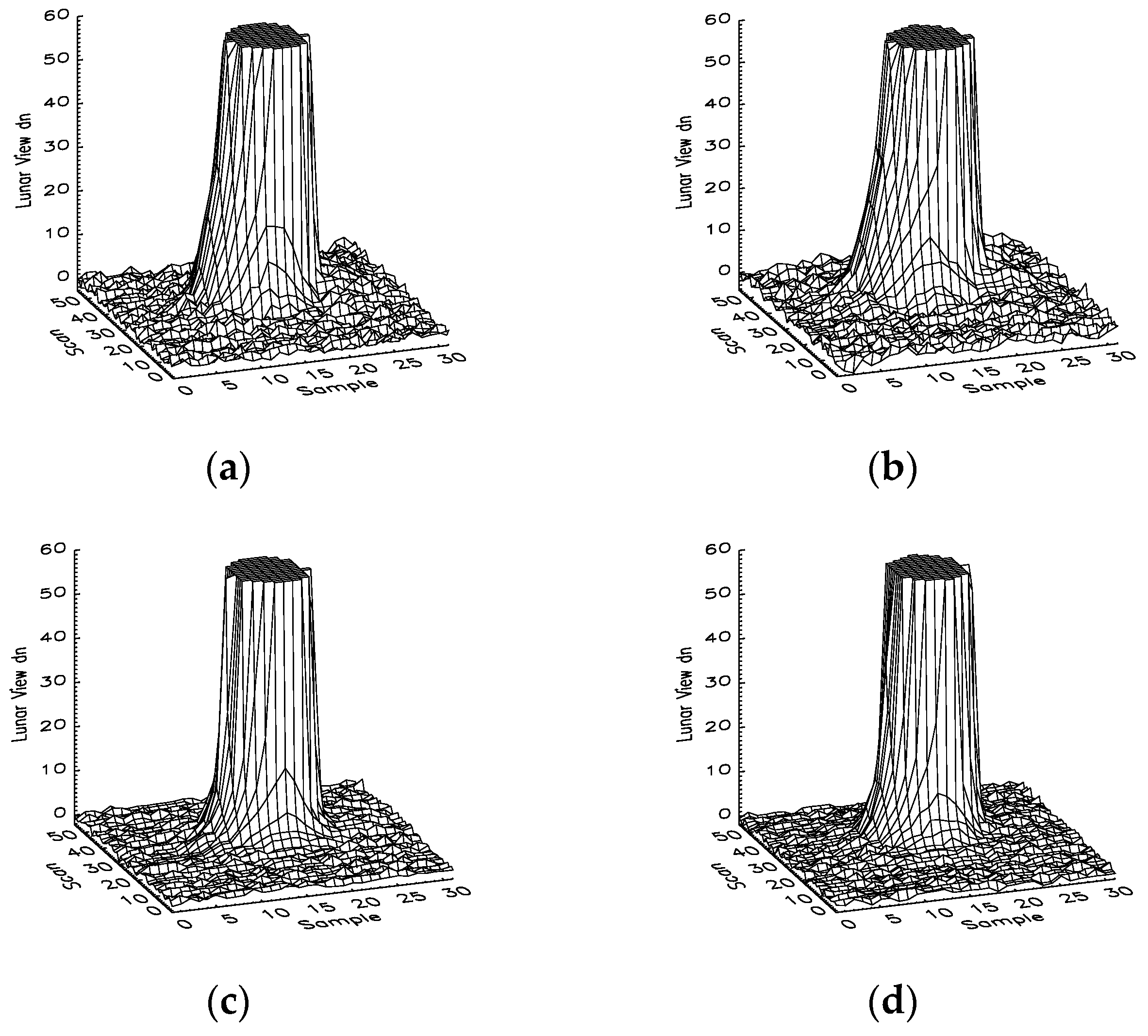
Figure 2 shows the three-dimensional images of the integrated lunar observations for Band I1 Detector 16, Band M1 Detector 8, Band M6 Detector 8, and Band M11 Detector 8 as observed on 2 April 2012. The z-axis labels the magnitude of the background-subtracted lunar signal, the x-axis labels the along-scan direction (samples or frames), and the y-axis labels the along-track direction (scans). To identify the small crosstalk effect, the lunar responses are truncated to 60 digital number (dn) counts to make the crosstalk signals more pronounced if they exist. The maximum lunar view responses for these bands are as high as 257, 705, 3092, and 510 dn, respectively. As discussed previously, the sizes of the lunar images along the scan are about 18, 27, 9, and 9 pixels for Band I1 (imaging band), Band M1 (dual-gain M-band), Band M6 (single-gain M-band), and Band M11 (single-gain M-band), respectively, which are confirmed by the images in Figure 2.
A clear cylinder of the signals with magnitude 60 dn is seen in the center of each image in Figure 2. No observable hills or valleys are present in the neighboring frames. In other words, no “ghost image” is seen around the edge of these lunar images. This indicates that there is no observable crosstalk effect in these bands. We have also examined the lunar images of other RSB and found that there is no observable crosstalk effect in them as well. This is consistent with what was found and reported on early in the mission [15]. As mentioned in the Introduction section, a significant crosstalk effect was found in SNPP VIIRS RSB as well as in TEB during the pre-launch sensor characterization. Nevertheless, the crosstalk effect in RSB diminished after launch, resulting in better performance of the RSB in orbit.
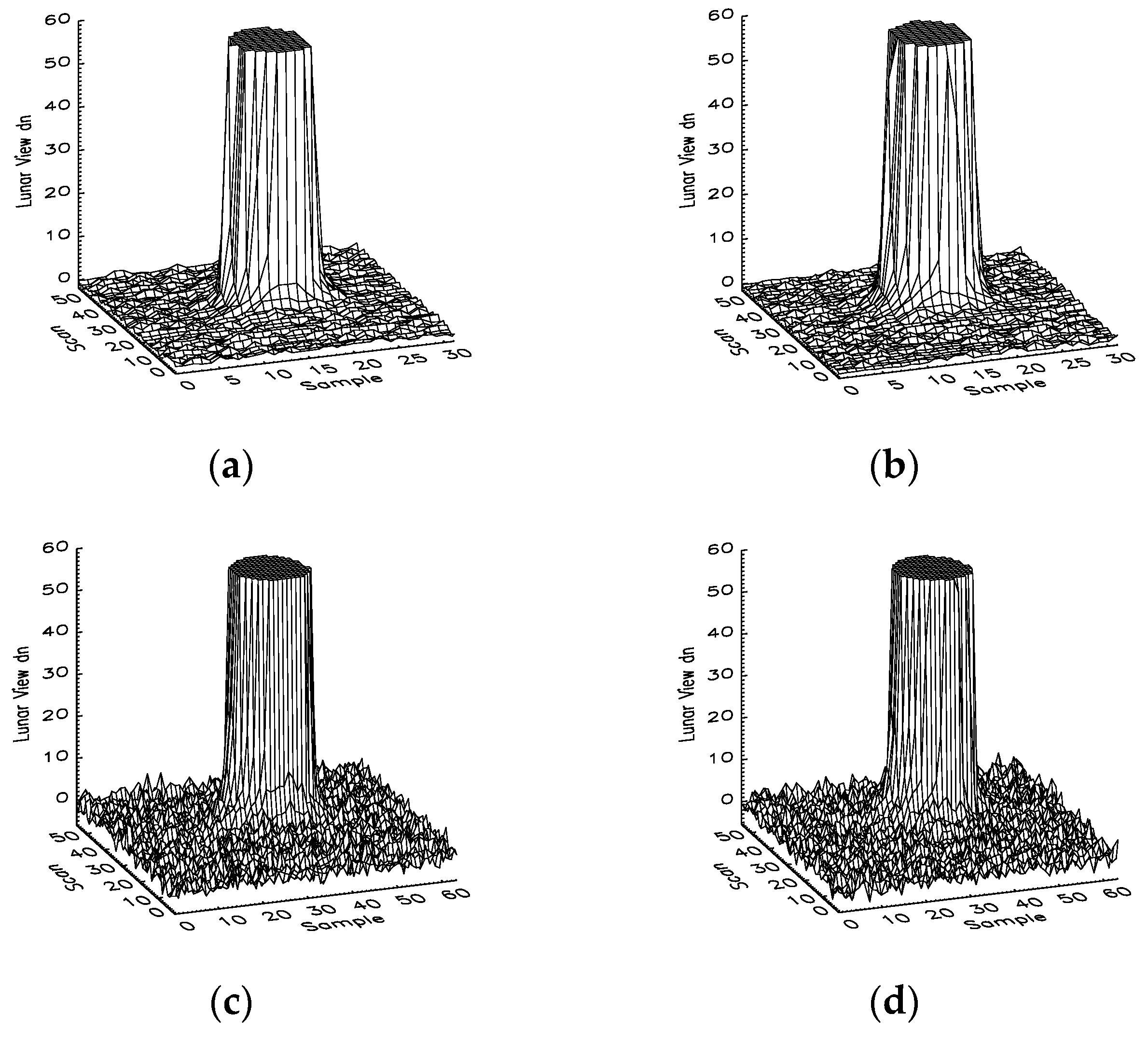
Figure 3 shows the lunar images observed by Band M14 Detector 8, Band M14 Detector 9, Band M15 Detector 8, and Band M15 Detector 9. It is clearly seen that there are tails at the left edges of the lunar images. These tails are the manifestation of the crosstalk contaminations, which can only come from the bands on the LWIR FPA since the two bands are located on the LWIR FPA as shown in Figure 1. The left side tails in the lunar images indicate that the sending bands view the Moon at an earlier time than the receiving bands. In other words, the sending bands are located to the right side of the receiving bands on the LWIR FPA according to the ground scan direction labeled in Figure 1. This is confirmed by the fact that there is no band on the FPA to the left side of Band M14. By comparing Figure 3a,b, it is seen that the crosstalk effect is larger in Band M14 Detector 9 than in Band M14 Detector 8 since the tail in Figure 3b is larger than that in Figure 3a. By checking the lunar images, observed on the same day, of all 16 detectors in Band M14, it can be concluded that the crosstalk contaminations in the detectors with an odd detector number are larger than those with an even detector number. This is understandable because the 16 detectors of Band M14 are grouped into two groups, one with odd detector numbers and the other with even detector numbers, into two columns on the LWIR FPA separated by three frames (aggregated pixels). Since the contaminations are from bands on the right of the band, odd-numbered detectors are closer to the sending bands than the even-numbered detectors and thus are expected to have larger electromagnetic interference. From Figure 3c,d, a similar phenomenon is seen in Band M15 where the crosstalk contamination in Detector 9 is larger than that in Detector 8. By checking the lunar images of all detectors in Band M15, the same pattern observed in Band M14 is seen and the same conclusion for Band M14 is drawn. In principle, M15 may have crosstalk contamination from band M14 and the contamination should appear on the right side of the lunar images in Figure 3c,d, since M14 is located on the left side of M15. From Figure 3c,d, it can be seen that the tails on the right side of the two lunar images are much smaller than those on the left side. In other words, the crosstalk contaminations from M14 to M15 are much smaller than those from M16. In this analysis, we will focus on the crosstalk contaminations from M16 to M15. By comparing Figure 3a–d, it is also seen that the crosstalk contamination in Band M14 is larger than that in Band M15.
Figure 4a–d shows the lunar images observed by Band M13 Detector 8, Band M13 Detector 9, Band M16 Detector 8, and Band M16 Detector 9, respectively. The two bands are located on the SW/MIR FPA and LWIR FPA, respectively. Since Band M13 is a dual-gain band, the two lunar images of the band have more frames or samples in the along-scan direction. Different from Band M14 and M15, the observable tails in the four lunar images occur at the right side of the cylinders. This indicates that crosstalk contamination for each of them comes from the bands located to the left side on the same FPA. In fact, Band M13 is located on the right end of the SW/MIR FPA and thus there are only bands to its left side on the FPA. Same as in Bands M14 and M15, the detectors in each of the Bands M13 and M16 are classified into two groups distributed into two columns separated by three aggregated pixels of a single-gain band on its FPA. Same as for all the other TEB, the even detectors are located to the left side of the odd detectors. Since for Bands M13 and M16 the crosstalk contaminations come from the sending bands located to their left side, it is expected that the crosstalk contamination in the even detectors should be larger than those in the odd detectors for both bands. This pattern is different and is, in fact, exactly the opposite from that in Bands M14 and M15. By comparing Figure 4a–d, the crosstalk contaminations, represented by the tails in the right side of the lunar images, in the even detectors are indeed larger than those in the odd detectors. There are also small tails on the left side of the lunar images in Figure 4c,d, which is induced by crosstalk contamination from band I5 located to the right side of band M16 on the same focal plane.
Figure 5a,b shows the lunar images observed by Band I5 Detectors 16 and 17 on 2 April 2012. At the right side of the images, there are visible tails indicating contaminations from the bands to its left side on the LWIR FPA. Since Band I5 is located at the right end in the FPA, crosstalk contaminations can only come from the bands located to its left side. By comparing Figure 5a,b, differences between the odd and even detectors are observable and the crosstalk contaminations in even detectors are larger than those in the odd detectors for the same reason as in Bands M13 and M16. Figure 6a–d show the lunar images for Band M12 Detector 8, Band M12 Detector 9, Band I4 Detector 16, and Band I4 Detector 17, respectively. There are no clear tails around the edges of the lunar images. There are either no crosstalk contaminations or they are much smaller than those in the other TEB as discussed above.
3. Crosstalk Correction Algorithm
A linear model has been developed by Sun et al. [24,25,26,27,28,29,30,31] to relate the crosstalk contamination in a receiving band to the signals in the sending bands. The crosstalk contamination in SNPP VIIRS can be identically expressed as
where Br, Dr, Bs, and Ds represent the receiving band, receiving detector, sending band, and sending detector, respectively; F is the pixel number along the scan of band Br; FBD is the pixel shift between band B detector D and the focal plane reference axis shown in Figure 1; c(Br, Dr, Bs, Ds) is the crosstalk coefficient for the crosstalk from band Bs detector Ds to band Br detector Dr; is the measured background-subtracted instrument response of band Bs detector Ds; and is the crosstalk signal from the sending bands to the receiving detector of the receiving band. The pixel sizes of the original lunar data are different for different bands due to pixel size differences of the I-bands and M-bands (see Table 1) and different statuses of the aggregation application for dual- and single-gain bands. Equation (1) requires the pixel sizes of the receiving band and sending bands to be the same. As long as the pixel sizes are the same, it does not matter whether the data for instrument response in Equation (1) are aggregated.
Considering that the smooth change of temperature is typical of Earth scenes, the detectors can be grouped together to be averaged. However, an extra detail appears for SNPP VIIRS, and that is the parity phenomenon, to be demonstrated later, for which the even-numbered and odd-numbered detectors behave as two distinctively separate groups. Thus, for SNPP VIIRS, Equation (1) can be further approximated as for a TEB [24].
where Pr is the parity of detector Dr and P is the detector parity of the sending band Bs; the brackets indicate the average over the detectors with parity P of the sending band Bs; C(Br, Dr, Bs, P) is the effective crosstalk coefficient from the sending band Bs detectors with parity P to the receiving band Br detector Dr. Equation (2) can be applied to an area within an image, within which the signals are mainly crosstalk contamination, to derive the crosstalk coefficients. Since the lunar surface is not uniform, one needs to use the summation of the dn over scans for each given frame or sample along-scan instead of the dn in Equation (2) to derive the crosstalk coefficients. The details of how to derive the crosstalk coefficients from the lunar observations have been well described in our previous work [24,26]. So far, the edges of the lunar images are known to be the most optimal for this purpose [24,25,26,27,28,29,30,31]. To remove the crosstalk contamination in the receiving bands, the crosstalk contamination described in Equations (1) or (2) is subtracted from the measured signals of the band in both routine and WUCD BB calibration [24,25,26,27,28,29,30,31], and also in Earth view (EV) observations. It is worth mentioning that there are also crosstalk contaminations among the detectors within the receiving band. One can include the intra-band crosstalk contribution in Equations (1) and (2) as well. However, the intra-band crosstalk contaminations in BB calibration and in EV observations cancel each other and the final impact of this crosstalk effect on the EV retrievals is negligible. Thus, we will focus on inter-band crosstalk contaminations in this analysis.
4. Crosstalk Coefficients
In this section, we derive the crosstalk coefficients using the scheduled lunar observations and the established linear algorithm. The main procedure is identical to previous work [24,26] except for the straightforward adaptation to separate the analysis to account for the parity phenomenon, as in Equation (2). In other words, the procedure used in this analysis to derive the crosstalk coefficients from the lunar observations is exactly the same as that used for the MODIS crosstalk analysis, except that here the odd and even detectors of a sending band are analyzed as separate bands. From the lunar imagery analysis, we identify the main sending bands for the following affected bands—M13, M14, M15, and M16. For each of these affected bands, there is only one sending band which needs to be considered as discussed in Section 2. It is worth mentioning that most SNPP VIIRS TEB saturate when they view the brightest part of the lunar surface. A scaling scheme is applied to estimate the instrument response at the saturated region for each band. This is achieved by a careful comparison with a corresponding image of an unsaturated band to reconstruct the dn in the saturated region via scaling [24,26]. After the application of the scaling, the peak numbers of the lunar images for bands M12–M16, which are either receiving bands or sending bands for the crosstalk contaminations of bands M13–M16, are 4114, 3638, 4464, 3930, 3875 dn, respectively. With the scaled lunar data, the coefficients are derived.
As already demonstrated in Section 2, Band M14 receives crosstalk contaminations from the bands located to its right side on the LWIR FPA. There are three such bands—M15, M16 (M16A and M16B), and I5—to the right of Band M14 that in principle can have crosstalk with Band M14. The analysis of the tails at the left side of the lunar images of Band M14 reveals that there are no crosstalk contaminations from Bands M16 and I5 or that the contributions from them are negligible. Thus, the crosstalk contaminations as demonstrated by the tails at the left side of the lunar images shown in Figure 3a,b come from Band M15. Figure 7a,b shows the crosstalk coefficients derived from the Band M14 lunar observations for the entire mission. In the plot, the coefficients are expressed in percentages, or simply 100 times the coefficients. It is easy to see that there are no visible long-term changes in the coefficients over time, although repeated fluctuations are obvious. The fluctuations are considered to come from the remaining uncertainties of the measurement, which are not significant in the context of this analysis. Figure 7a shows the crosstalk coefficients for all detectors of Band M14 from the odd detectors of Band M15. It is easy to see that the coefficients fall into two separate groups, based on the evenness, oddness, or parity of the detectors. The coefficients for the crosstalk contaminations in Band M14 for its odd detectors are about 0.25%, while those for the even detectors are close to zero. This is consistent with the fact that the odd detectors are located closer to Band M15. Figure 7b shows the crosstalk coefficients for all detectors of Band M14 from the even detectors of Band M15. Once again, the coefficients fall into two groups, one for odd detectors and the other for even detectors. For odd detectors, the crosstalk coefficients are about the same, and are close to 0.9%. For even detectors, they are much smaller, at close to 0.1%. As mentioned previously, it is difficult to separate the effect of electronic crosstalk and optical crosstalk. In other words, it is difficult to identify whether the crosstalk effect in M14 is induced by electronic crosstalk or optical crosstalk. Nevertheless, the dependence of the crosstalk effect on the distance between a receiving detector and a sending detector indicates that the crosstalk is most likely optical crosstalk.
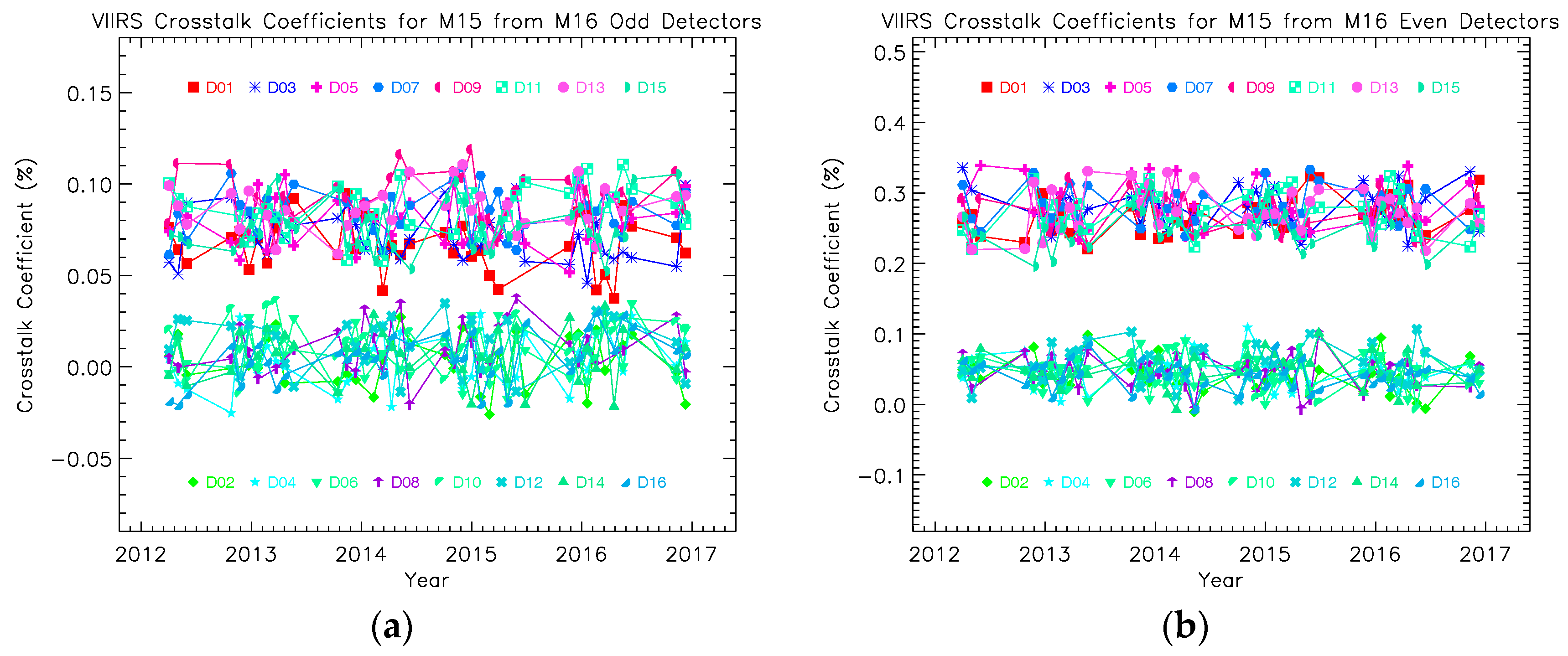
Figure 8a,b displays the crosstalk coefficients derived from the lunar observations for Band M15. It is determined that only the crosstalk contaminations from Band M16 may have non-negligible contributions to the detectors of Band M15. Figure 8a,b shows the crosstalk coefficients derived from the lunar observations. Same as for Band M14, Band M15 coefficients show no long-term trend with time although with observable fluctuations due to the uncertainties of the measurement. Figure 8a displays the coefficients for all detectors of Band M15 for the crosstalk contaminations from the odd detectors of Band M16, while Figure 8b displays the coefficients for the contaminations from the even detectors of Band M16. In both Figure 8a,b, the coefficients are again grouped into two groups as expected. Again, the crosstalk coefficients for Band M15 for its odd detectors are larger than those for its even detectors. Also, the crosstalk contaminations from Band M16 as the sending band are larger from its even detectors than the odd ones due to their arrangement on the LWIR FPA. This suggests that the crosstalk in M15 is probably mainly optical crosstalk, consistent with that in M14. Comparing Figure 7 and Figure 8, it is seen that the crosstalk contaminations in Band M15 are smaller than those in Band M14. However, it is important to point out that this assessment based on the crosstalk coefficients may not necessarily translate to the same order for the actual impacts of the crosstalk contaminations in science products.
Figure 9a,b displays the crosstalk coefficients derived from the lunar observations for Band M13. As mentioned in Section 2, Band M13 is located at the right end of the SW/MIR FPA, and therefore its crosstalk contaminations can only come from the bands to its left side. Furthermore, the crosstalk effect can only induce artifacts around the right side of the lunar images, as demonstrated in Figure 4a,b. Similar to Bands M14 and M15 receiving contributions from only one neighboring sending band, the only non-negligible crosstalk contaminations for Band M13 comes from Band M12, its nearest band neighbor on the FPA. Figure 9a,b show the Band M13 crosstalk coefficients derived from the lunar imagery analysis. Again, the same as for Bands M14 and M15, the coefficients do not show long-term trends with time. Figure 9a displays the coefficients for all detectors of Band M13 for the crosstalk contaminations from the odd detectors of Band M12, while Figure 9b shows the coefficients for the contaminations from the even detectors of Band M12. Again, the coefficients in both Figure 9a,b expectedly fall into two groups. However, different from Bands M14 and M15, the Band M13 crosstalk coefficients for odd detectors are smaller than those for even detectors, and the crosstalk contaminations from Band M12 are smaller for its even detectors than for its odd detectors, due to the relative positions of the receiving and sending bands being opposite of those in the cases of Bands M14 and M15. Comparing Figure 7, Figure 8 and Figure 9, it is seen that the crosstalk contaminations in Band M13 are smaller than those in Band M14, but larger than those in Band M15. Again, this assessment is based on the crosstalk coefficients but the actual impacts of the crosstalk contaminations may not necessarily follow this order.
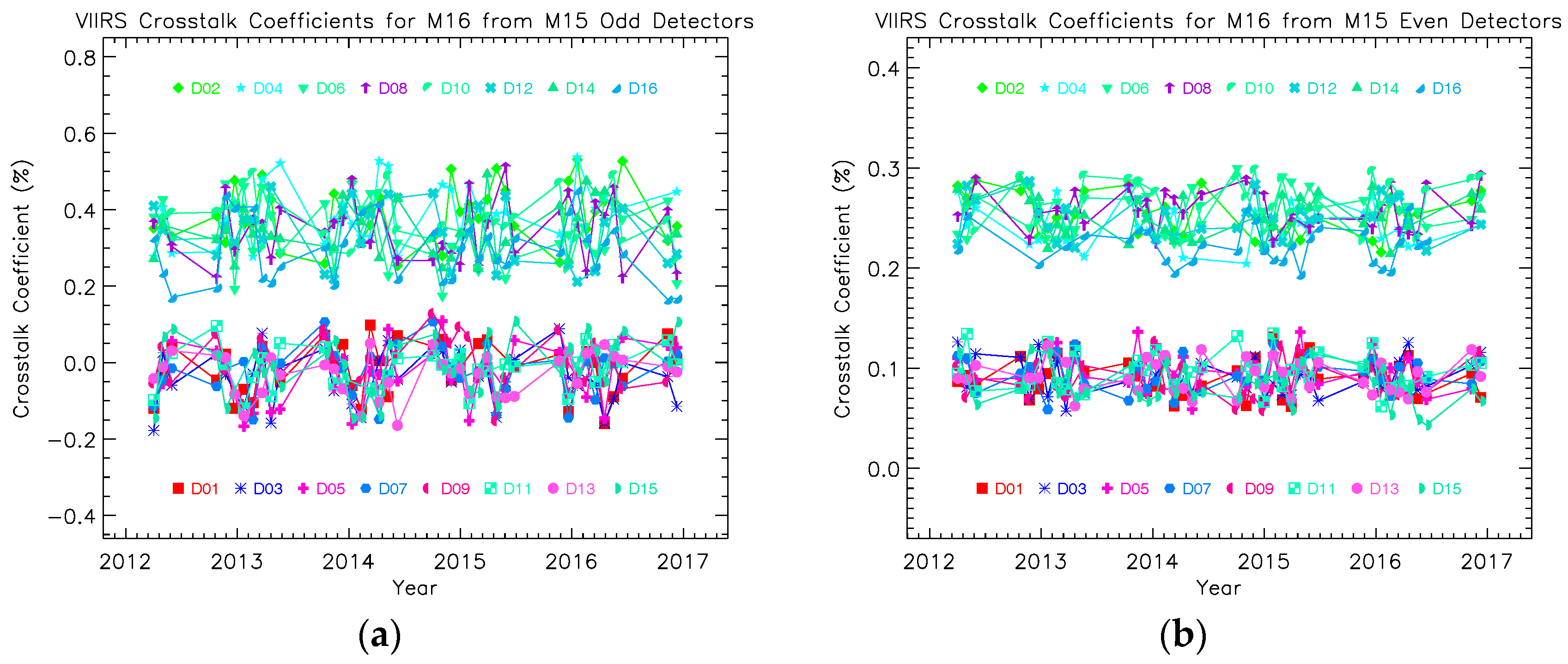
Figure 10a,b shows the crosstalk coefficients derived from the lunar imagery analysis for Band M16. As discussed in Section 2, Band M16 is a TDI band combining Bands M16A and M16B. In principle, crosstalk contaminations can exist between the detectors of M16A and M16B, but it is difficult to separate them in current lunar images unless the lunar data obtained by each individual of the two bands M16A and M16B are explicitly provided. In this analysis, we assume that the effect of the crosstalk between Bands M16A and M16B is small and that effectively all contributions come from other bands, specifically from Band I5 located to its right side and Bands M14 and M15 to its left side. The crosstalk contaminations from Band I5 should appear at the left side of the lunar images displayed in Figure 4c,d as previously discussed. Comparing Figure 2, Figure 3 and Figure 4, it can be seen that the crosstalk contaminations from Band I5 to Band M16 are considerably smaller than those from Band M15 to Band M14 and from Band M16 to Band M15, although small tails are observable on the left side of the lunar images in Figure 4c,d. They are considered to be negligible in this analysis and we will focus on the crosstalk contaminations that occurred at the right side of the lunar images, which come from the bands to the left side of Band M16 on the LWIR FPA. Similarly, as previously discussed for Bands M14 and M15 with each receiving interference signals from the nearest neighboring band, for M16 only the contaminations from Band M15 need to be considered in this analysis. Similar to Bands M13 to M15, there are no changing long-term trends in the coefficients. Figure 10a displays the coefficients for all detectors of band M16 for the crosstalk contaminations from the odd detectors of Band M15, while Figure 10b shows the coefficients for the contaminations from the even detectors of Band M15. As expected, the coefficients in both Figure 10a,b fall into two groups. Different from Bands M14 and M15 and similar to Band M13, the crosstalk coefficients for the odd detectors are smaller than those for the even detectors and crosstalk contaminations from the even detectors of Band M15 are smaller than those from the odd detectors, due to the relative positions of the receiving and sending bands being in opposite arrangement to those of Bands M14 and M15. Comparing Figure 7, Figure 8, Figure 9 and Figure 10, it is seen that the crosstalk contaminations in Band M16 are smaller than those in Band M14, but larger than those in Bands M13 and M15.
Band I5 is located at the right end of the LWIR FPA. The lunar images in Figure 5a,b demonstrate that there are visible crosstalk contaminations from bands to its left side on the FPA, especially Band M16. In principle, we can derive the crosstalk coefficients for Band I5 with the same approach as applied to Bands M13–M16. However, the image bands collect the data twice as frequently as compared to the moderate bands. Specifically, half of the samples for an image band are taken at about the same times as the moderate bands, while the other half of the samples are taken when the moderate bands do not take data. So the crosstalk effect for the sets of samples is different as demonstrated in Terra MODIS Band 2 [41], where regular brighter and darker spots occur in the EV imagery due to differences of the crosstalk contaminations among the subframes from the other bands. We therefore do not discuss the crosstalk effect further for Band I5 in this analysis but will do so in a follow-up paper, where crosstalk correction will also be applied to remove the contamination in both BB calibration and in EV retrievals.
It is, however, important to raise caution concerning the current result for M16 due to the complication of it being a dual band, namely M16A and M16B. The derived coefficient characterizing the effect of M15 on M16 can, in principle, contain two separate contributions—one from M15 to M16A and the other from M16A to M16B. The direct application of the crosstalk coefficient to mitigate the effect of M15 on M16 may result in overcompensation, and therefore is an issue to be addressed when the correction is to be applied. For the current analysis, the purpose of demonstrating the crosstalk effect in M16 is fully achieved. It is worth noting that the near field response (NFR) may bring some artifacts around the edge of a lunar image as well, if it has a non-negligible effect. However, the NFR should not depend on detector parity. Thus, the artifacts seen in the lunar images of the SNPP VIIRS TEB should be mainly due to the crosstalk contaminations as discussed.
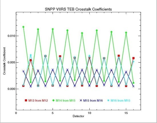
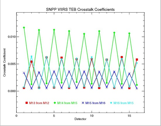
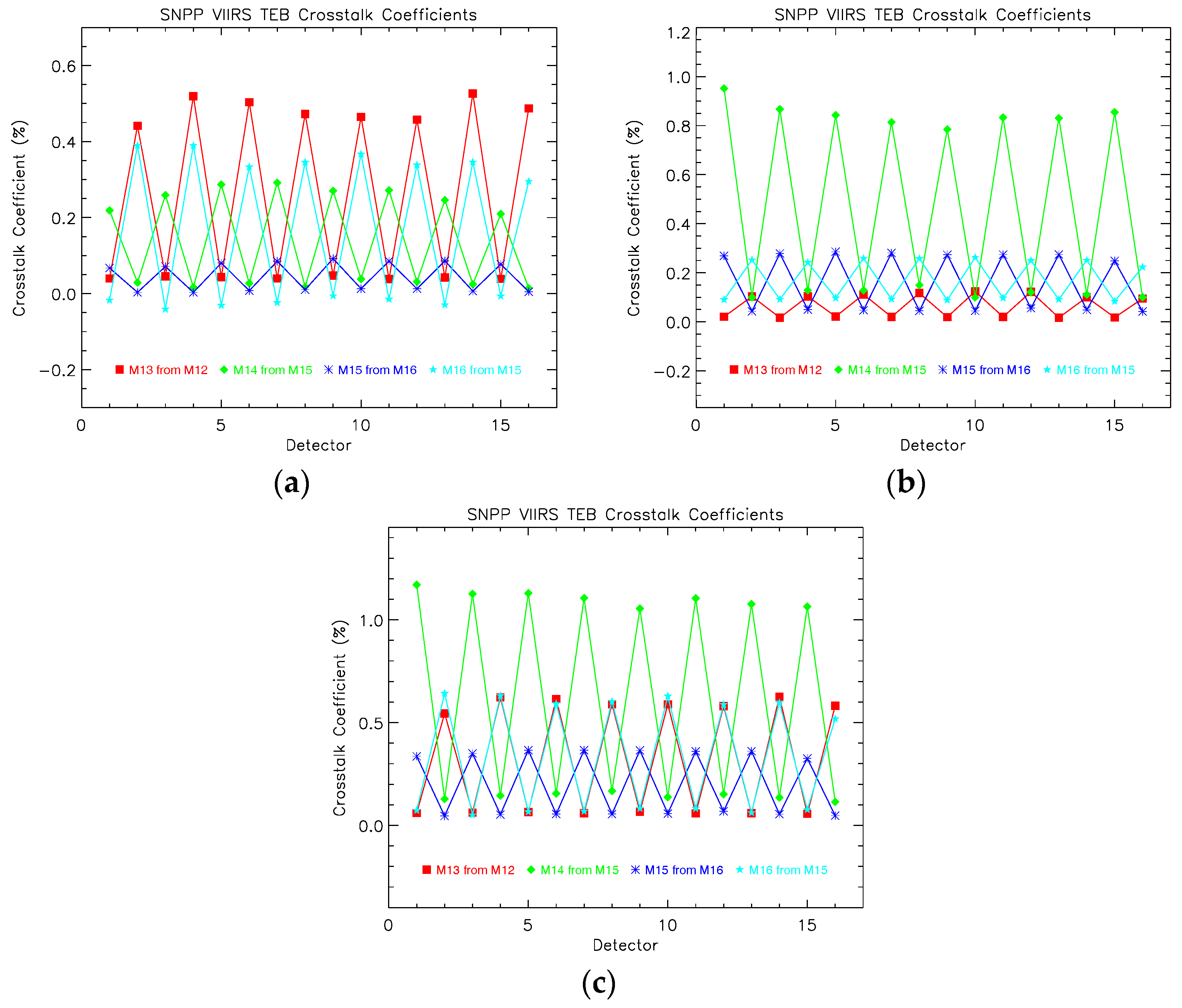
As demonstrated in Figure 7, Figure 8, Figure 9 and Figure 10, the crosstalk effect in SNPP VIIRS has remained sufficiently stable to allow for a smooth averaging over time to represent the effect as a constant. Figure 11a,b shows the time-averaged crosstalk coefficients for odd and even detectors of the sending bands, respectively, for Bands M13–M16. Since the EV temperature is relatively smooth over a few kilometers, the signals in the odd and even detectors for a TEB are expectedly about the same. Thus, we can further sum up the averaged coefficients in Figure 11a,b for each individual receiving detector and band for comparison purposes. Figure 11c shows the summations of the averaged crosstalk coefficients in Figure 11a,b. First, we can see that Band M14 has the largest crosstalk contamination, followed by Bands M13 and M16, and finally Band M15. Second, there is a very clear difference between the odd and even detectors in all four bands. Third, Bands M14 and M15 have the same odd-even pattern, while Bands M13 and M16 have the opposite odd-even pattern. This odd-even detector difference definitely can induce the currently known pattern in the calibration coefficients derived from the BB calibration and scene-dependent striping in its EV retrievals for each of the four bands. For any EDR products that use a combination of these bands, the striping can become even more pronounced if two bands of opposing odd-even patterns, such as Bands M15 and M16 in Figure 11, are used. This is indeed the case with SST which uses the difference between M15 and M16 and can result in striping enhancement [18,19,37]. Because the crosstalk effect depends on the signals of the sending bands, its impact on SST can be further intensified in the WUCD calibration during which the BB temperature is raised. The reported artifacts appearing in the SST during the WUCD time periods [37] are consistent with this finding.
The crosstalk effect in SNPP VIIRS TEB is smaller compared to that in the MODIS LWIR PV bands, in which the crosstalk effect is not only strong but becomes increasingly more severe with time. Nevertheless, the crosstalk effect in SNPP VIIRS TEB is non-negligible and the features of the crosstalk contaminations match the properties of the artifacts [18,19,37] that have been found in SNPP VIIRS TEB since its launch. The direct connection of these observed artifacts to crosstalk contaminations in SNPP VIIRS is yet to be explicitly demonstrated, and their mitigation awaits further efforts. With the crosstalk coefficients derived in this analysis using the algorithm we have developed in our previous work, it is expected that the artifacts can be removed or significantly reduced. The further development towards this direction requires a different and more demanding analysis, and is outside the scope of this work.
5. Summary
The crosstalk effect in SNPP VIIRS has been examined. The existence of significant crosstalk contamination in TEB has been confirmed by the established lunar imagery analysis, while no observable crosstalk effect is found in RSB. The crosstalk effect in TEB is characterized and the crosstalk coefficients for Bands M13–M16 are derived from the analysis of the scheduled lunar observations. The crosstalk contaminations are both band and detector dependent. It is shown that Band M14 has the largest crosstalk contaminations among all TEB and its contaminations come from Band M15. The crosstalk effect for odd detectors is about 0.9%, which may induce significant impact in the EV retrievals of the band. A clear difference between the odd and even detectors for the affected bands is demonstrated, and this detector-based difference can induce striping in the EV imagery. In addition, the crosstalk contaminations induce errors in the derived EV retrievals and also the sudden changes in the EV brightness temperature during WUCD BB calibrations. In brief, the crosstalk contaminations in SNPP VIIRS TEB are large enough to affect the associated SDR and EDR products derived from these bands, with results such as striping in imagery and artifacts in SDR and EDR products during WUCD calibration events. This analysis conclusively finds the need to apply crosstalk correction to both the BB calibration and SDR code to improve the accuracy of the calibration coefficients and the EV retrievals.
Acknowledgments
We would like to thank Mike Chu for contributing very helpful insights. We would also like to thank Alex Ignatov for clarifying key issues in SST. The views, opinions, and findings contained in this paper are those of the authors and should not be construed as an official NOAA or U.S. Government position, policy, or decision.
Author Contributions
Junqiang Sun is the chief investigator of this topic and is responsible for the formulation and the crosstalk analysis using the Moon. Menghua Wang has provided vital support for this work.
Conflicts of Interest
The authors declare no conflict of interest.
References
- Cao, C.; Deluccia, F.; Xiong, X.; Wolfe, R.; Weng, F. Early on-orbit performance of the Visible Infrared Imaging Radiometer Suite (VIIRS) onboard the Suomi National Polar-orbiting Partnership (S-NPP) satellite. IEEE Trans. Geosci. Remote Sens. 2014, 52, 1142–1156. [Google Scholar] [CrossRef]
- Xiong, X.; Butler, J.; Chiang, K.; Efremova, B.; Fulbright, J.; Lei, N.; McIntire, J.; Oudrari, H.; Sun, J.; Wang, Z.; et al. VIIRS on-orbit calibration methodology and performance. J. Geophys. Res. Atmos. 2014, 119, 5065–5078. [Google Scholar] [CrossRef]
- Cao, C. Visible Infrared Imaging Radiometer Suite (VIIRS) Sensor Data Record (SDR) User’s Guide; National Oceanic and Atmospheric Administration (NOAA): Washington, DC, USA, 2013.
- Lei, N.; Wang, Z.; Fulbright, J.; Lee, S.; McIntire, J.; Chiang, K.; Xiong, X. Initial on-orbit radiometric calibration of the Suomi NPP VIIRS reflective solar bands. Proc. SPIE 2012, 8510, 111–115. [Google Scholar]
- Cardema, J.C.; Rausch, K.; Lei, N.; Moyer, D.I.; DeLuccia, F. Operational calibration of VIIRS reflective solar band sensor data records. Proc. SPIE 2012, 8510, 851019. [Google Scholar]
- Sun, J.; Wang, M. On-orbit calibration of the Visible Infrared Imaging Radiometer Suite reflective solar bands and its challenges using a solar diffuser. Appl. Opt. 2015, 54, 7210–7223. [Google Scholar] [CrossRef] [PubMed]
- Hass, E.; Moyer, D.; DeLuccia, F.; Rausch, K.; Fulbright, J. VIIRS solar diffuser bidirectional reflectance distribution function (BRDF) degradation factor operational trending and update. Proc. SPIE 2012, 8510, 851016. [Google Scholar]
- Fulbright, J.; Lei, N.K.; Chiang, K.; Xiong, X. Characterization and performance of the Suomi-NPP VIIRS solar diffuser stability monitor. Proc. SPIE 2012, 8510, 851015. [Google Scholar]
- Sun, J.; Wang, M. Visible infrared image radiometer suite solar diffuser calibration and its challenges using solar diffuser stability monitor. Appl. Opt. 2014, 36, 8571–8584. [Google Scholar] [CrossRef] [PubMed]
- Sun, J.; Wang, M. Radiometric Calibration of the Visible Infrared Imaging Radiometer Suite Reflective Solar Bands with Robust Characterizations and Hybrid Calibration Coefficients. Appl. Opt. 2015, 54, 9331–9342. [Google Scholar] [CrossRef] [PubMed]
- Sun, J.; Wang, M. VIIRS Reflective Solar Bands Calibration Progress and Its Impact on Ocean Color Products. Remote Sens. 2016, 8, 194. [Google Scholar] [CrossRef]
- Moyer, D.; McIntire, J.; De Luccia, F.; Efremova, B.; Chiang, K.; Xiong, X. VIIRS thermal emissive bands calibration algorithm and on-orbit performance. Proc. SPIE 2012, 4891, 392–401. [Google Scholar]
- Efremova, B.; McIntire, J.; Moyer, D.; Wu, A.; Xiong, X. S-NPP VIIRS thermal emissive bands on-orbit calibration and performance. J. Geophys. Res. Atmos. 2014, 119, 10859–10875. [Google Scholar] [CrossRef]
- Sun, J.; Xiong, X. Solar and lunar observation planning for Earth-observing sensor. Proc. SPIE 2011, 8176, 817610. [Google Scholar]
- Sun, J.; Xiong, X.; Butler, J. NPP VIIRS on-orbit calibration and characterization using the Moon. Proc. SPIE 2012, 8510, 85101I. [Google Scholar]
- Xiong, X.; Sun, J.; Fulbright, J.; Wang, Z.; Butler, J. Lunar calibration and performance for s-npp viirs reflective solar bands. IEEE Trans. Geosci. Remote Sens. 2016, 54, 1052–1061. [Google Scholar] [CrossRef]
- Liu, Q.; Cao, C.; Weng, F. Striping in the Suomi NPP VIIRS Thermal Bands through Anisotropic Surface Reflection. J. Atmos. Ocean. Technol. 2013, 30, 2478–2487. [Google Scholar] [CrossRef]
- Bouali, M.; Ignatov, A. Adaptive reduction of striping for improved sea surface temperature imagery from Suomi National Polar Orbiting Partnership (S-NPP) Visible Infrared Imaging Radiometer Suite (VIIRS). J. Atmos. Ocean. Technol. 2014, 31, 150–163. [Google Scholar] [CrossRef]
- Mikelsons, K.; Ignatova, A.; Boualic, M.; Kihaia, Y. A fast and robust implementation of the adaptive destriping algorithm for SNPP VIIRS and Terra/Aqua MODIS SST. Proc. SPIE 2015, 9459. [Google Scholar] [CrossRef]
- Mikelsons, K.; Wang, M.; Jiang, L.; Bouali, M. Destriping algorithm for improved satellite-derived ocean color product imagery. Opt. Express 2014, 22, 28058–28070. [Google Scholar] [CrossRef] [PubMed]
- Moeller, C.; McIntire, J.; Schwarting, T.; Moyer, D.; Costa, J. Suomi NPP VIIRS spectral characterization: Understanding multiple RSR releases. Proc. SPIE 2012, 8510, 85101S. [Google Scholar]
- Padula, F.; Cao, C. Detector-level spectral characterization of the Suomi NPP VIIRS long-wave infrared bands M15 & M16. Appl. Opt. 2015, 54, 5109–5116. [Google Scholar] [PubMed]
- Wang, Z.; Cao, C. Assessing the Effects of Suomi NPP VIIRS M15/M16 Detector Radiometric Stability and Relative Spectral Response Variation on Striping. Remote Sens. 2016, 8, 145. [Google Scholar] [CrossRef]
- Sun, J.; Madhavan, S.; Wenny, B.; Xiong, X. Terra MODIS band 27 electronic crosstalk: Cause, impact, and mitigation. Proc. SPIE 2011, 8176, 81760Z. [Google Scholar]
- Sun, J.; Madhavan, S.; Wang, M. Crosstalk effect mitigation in black body warm-up cool-down calibration for terra MODIS long wave infrared photovoltaic bands. J. Geophys. Res. Atmos. 2016, 121, 8311–8328. [Google Scholar] [CrossRef]
- Sun, J.; Xiong, X.; Madhavan, S.; Wenny, B.N. Terra MODIS band 27 electronic crosstalk effect and its removal. IEEE Trans. Geosci. Remote Sens. 2014, 52, 1551–1561. [Google Scholar]
- Sun, J.; Xiong, X.; Li, Y.; Madhavan, S.; Wu, A.; Wenny, B.N. Evaluation of radiometric improvements with electronic crosstalk correction for terra MODIS band 27. IEEE Trans. Geosci. Remote Sens. 2014, 52, 6497–6507. [Google Scholar]
- Sun, J.; Madhavan, S.; Xiong, X.; Wang, M. Investigation of the electronic crosstalk in terra MODIS band 28. IEEE Trans. Geosci. Remote Sens. 2015, 53, 5722–5733. [Google Scholar]
- Sun, J.; Madhavan, S.; Xiong, X.; Wang, M. Long-term trend induced by electronic crosstalk in terra MODIS band 29. J. Geophys. Res. Atmos. 2015, 120, 9944–9954. [Google Scholar] [CrossRef]
- Sun, J.; Madhavan, S.; Wang, M. Investigation and mitigation of the crosstalk effect in terra MODIS band 30. Remote Sens. 2016, 8, 249. [Google Scholar] [CrossRef]
- Sun, J.; Wang, M. Electronic crosstalk in Aqua MODIS long-wave infrared photovoltaic bands. Remote Sens. 2016, 8, 806. [Google Scholar] [CrossRef]
- Sun, J.; Xiong, X. MODIS polarization sensitivity analysi. IEEE Trans. Geosci. Remote Sens. 2007, 45, 2383–2393. [Google Scholar] [CrossRef]
- Sun, J.; Xiong, X.; Wuluschka, E.; Wang, M. Suomi National Polar-Orbiting Partnership Visible Infrared Imaging Radiometer Suite polarization sensitivity analysis. Appl. Opt. 2016, 55, 7645–7658. [Google Scholar] [CrossRef] [PubMed]
- Sun, J.; Che, N. Preliminary Results for Crosstalk among FU1 VIS/NIR bands from VIIRS FU1 STR-397 Test. NICST_MEMO_07_008. 7 March 2007. [Google Scholar]
- Che, N.; Pan, C.; Sun, J. Preliminary analysis of FU1 STR-430 xtalk test using a horizontal knife edge reticle. NICST_MEMO_07_013. 3 April 2007. [Google Scholar]
- Schwarting, T.; Lee, S. VCST VIIRS F1 Optical Crosstalk from FP-16 testing in the LWIR Focal Plane. NICST_MEMO_11_012. 4 October 2011. [Google Scholar]
- Ignatov, A. JPSS SST STAR Progress Report. In Proceedings of the STAR 2016 JPSS Annual Science Team Meeting, College Park, MD, USA, 11 August 2016. [Google Scholar]
- Moyer, D.; De Luccia, F.; Moy, G.; Wallisch, C. S-NPP VIIRS Thermal Emissive Band HAM Modification Study to Improve WUCD SDRs. Presentation to the VIIRS SDR Team. 2 August 2016. [Google Scholar]
- Wang, W.; Cao, C. VIIRS TEB Potential Improvements. Proceedings of STAR JPSS Annual Science Team Meeting, College Park, MD, USA, 9 August 2016. [Google Scholar]
- Sun, J.; Xiong, X.; Barnes, W.L.; Guenther, B. MODIS reflective solar bands on-orbit lunar calibration. IEEE Trans. Geosci. Remote Sens. 2007, 43, 2383–2393. [Google Scholar] [CrossRef]
- Sun, J.; Xiong, X.; Che, N.; Angal, A. Terra MODIS band 2 electronic crosstalk: cause, impact, and mitigation. Proc. SPIE 2010, 7826. [Google Scholar] [CrossRef]
Figure 1.
VIIRS focal plane assembly (FPA).

Figure 2.
Lunar images observed by SNPP VIIRS reflective solar bands I1, M1, M6, and M11 on 2 April 2012: (a) Band I1 detector 16, (b) Band M1 detector 8, (c) Band M6 detector 8, and (d) Band M11 detector 8.
Figure 2.
Lunar images observed by SNPP VIIRS reflective solar bands I1, M1, M6, and M11 on 2 April 2012: (a) Band I1 detector 16, (b) Band M1 detector 8, (c) Band M6 detector 8, and (d) Band M11 detector 8.
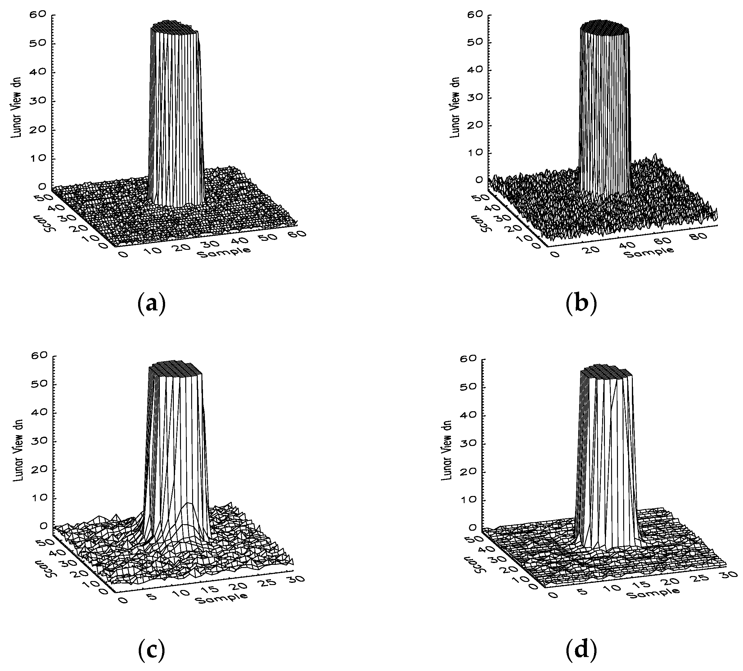
Figure 3.
Lunar images observed by SNPP VIIRS thermal emissive Bands M14 and M15 on 2 April 2012: (a) Band M14 Detector 8, (b) Band M14 Detector 9, (c) Band M15 Detector 8, and (d) Band M15 Detector 9.
Figure 3.
Lunar images observed by SNPP VIIRS thermal emissive Bands M14 and M15 on 2 April 2012: (a) Band M14 Detector 8, (b) Band M14 Detector 9, (c) Band M15 Detector 8, and (d) Band M15 Detector 9.

Figure 4.
Lunar images observed by SNPP VIIRS thermal emissive bands M13 and M16 on 2 April 2012: (a) Band M13 Detector 8; (b) Band M13 Detector 9; (c) Band M16 Detector 8; and (d) Band M16 Detector 9.
Figure 4.
Lunar images observed by SNPP VIIRS thermal emissive bands M13 and M16 on 2 April 2012: (a) Band M13 Detector 8; (b) Band M13 Detector 9; (c) Band M16 Detector 8; and (d) Band M16 Detector 9.
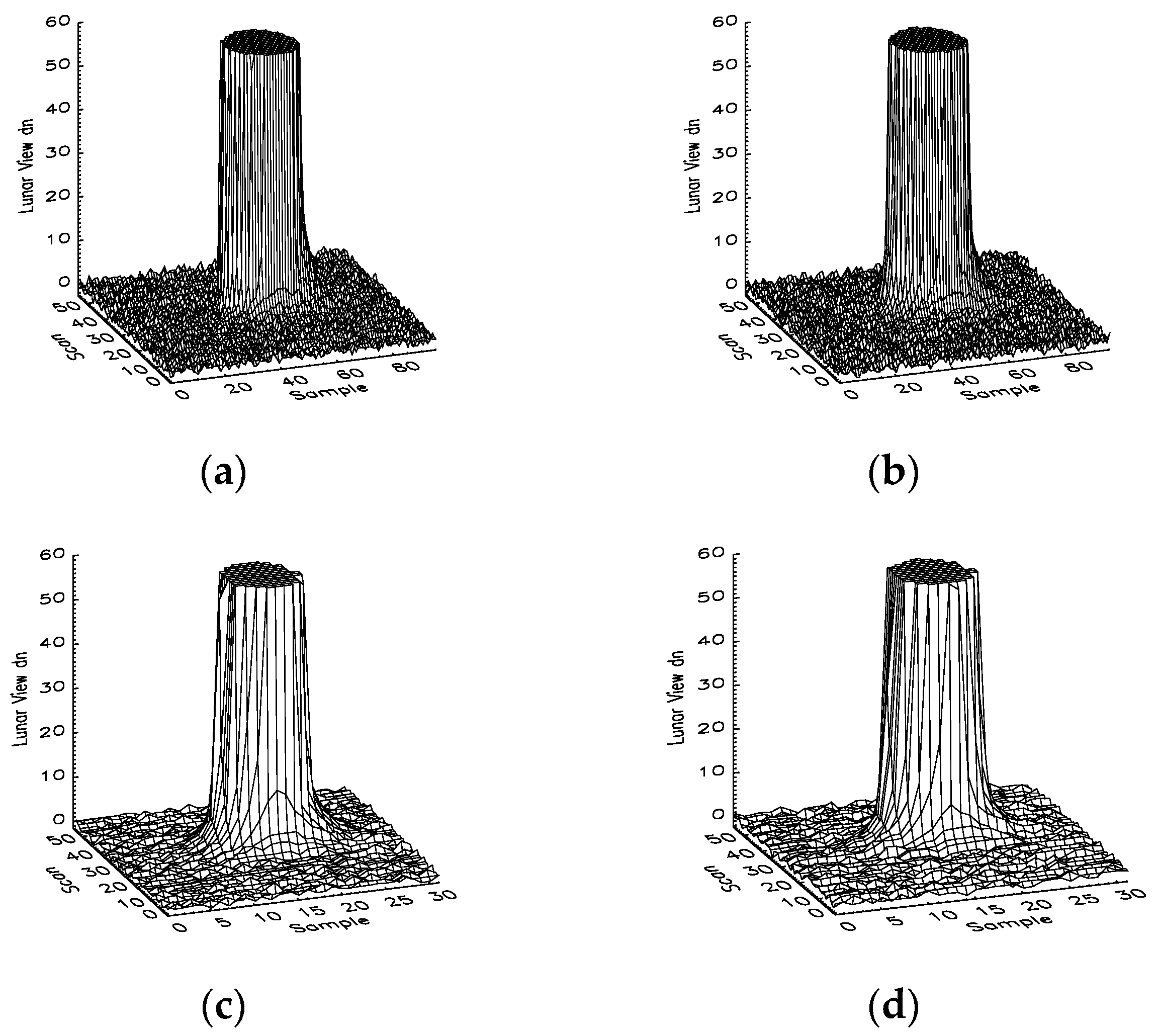
Figure 5.
Lunar images observed by the SNPP VIIRS thermal emissive band I5 on 2 April 2012: (a) detector 16 and (b) detector 17.
Figure 5.
Lunar images observed by the SNPP VIIRS thermal emissive band I5 on 2 April 2012: (a) detector 16 and (b) detector 17.
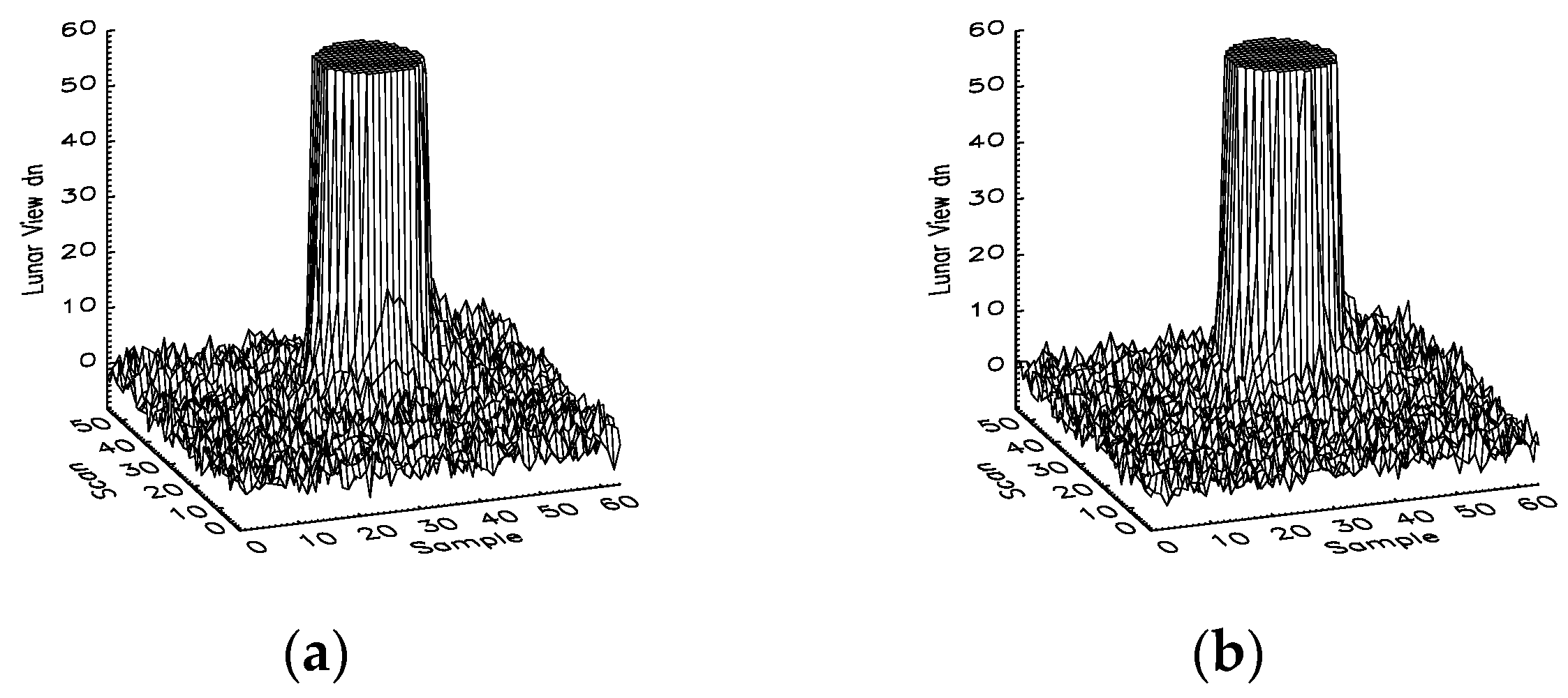
Figure 6.
Lunar images observed by SNPP VIIRS thermal emissive bands M12 and I4 on 2 April 2012: (a) Band M12 Detector 8, (b) Band M12 Detector 9, (c) Band I4 Detector 16, and (d) Band I4 Detector 17.
Figure 6.
Lunar images observed by SNPP VIIRS thermal emissive bands M12 and I4 on 2 April 2012: (a) Band M12 Detector 8, (b) Band M12 Detector 9, (c) Band I4 Detector 16, and (d) Band I4 Detector 17.

Figure 7.
SNPP VIIRS Band M14 crosstalk coefficients for sending Band M15: (a) odd detectors and (b) even detectors.
Figure 7.
SNPP VIIRS Band M14 crosstalk coefficients for sending Band M15: (a) odd detectors and (b) even detectors.
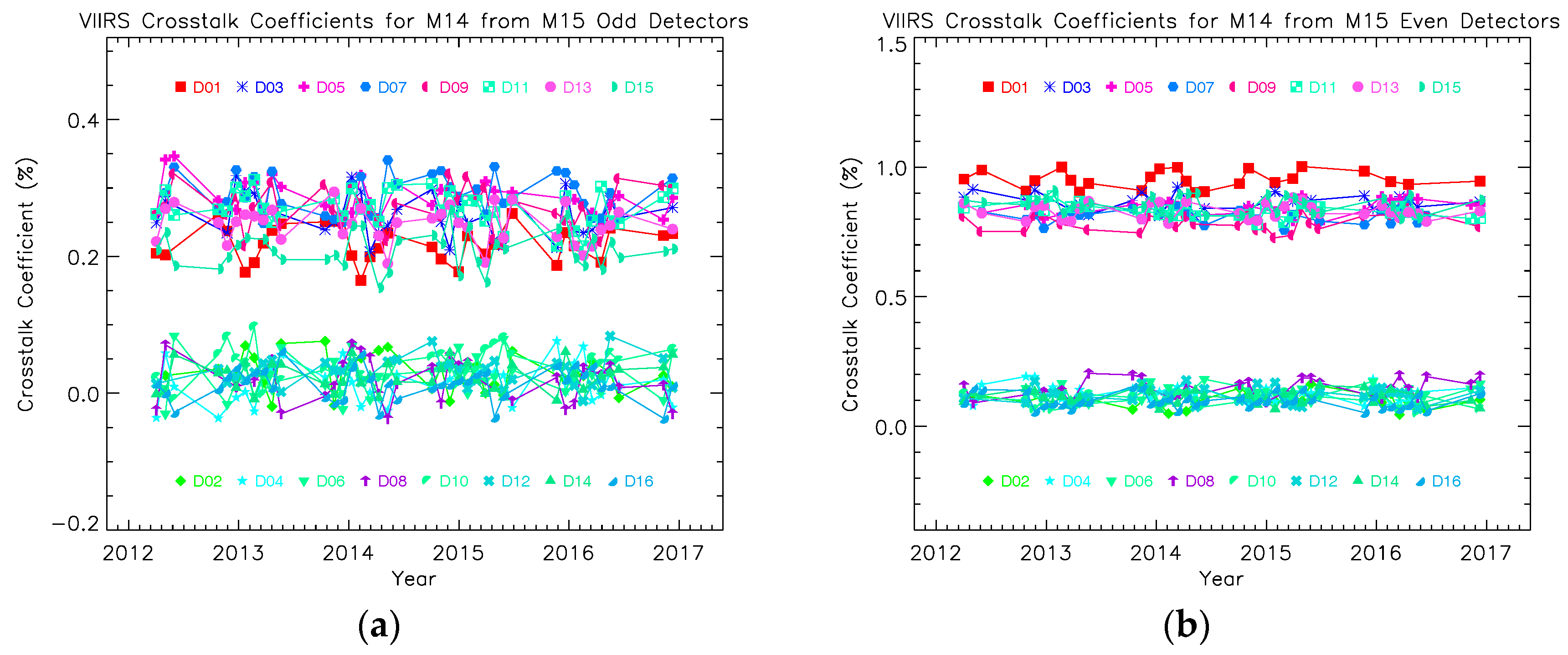
Figure 8.
SNPP VIIRS Band M15 crosstalk coefficients for sending Band M16: (a) odd detectors and (b) even detectors.
Figure 8.
SNPP VIIRS Band M15 crosstalk coefficients for sending Band M16: (a) odd detectors and (b) even detectors.

Figure 9.
SNPP VIIRS Band M13 crosstalk coefficients for sending Band M12: (a) odd detectors and (b) even detectors.
Figure 9.
SNPP VIIRS Band M13 crosstalk coefficients for sending Band M12: (a) odd detectors and (b) even detectors.
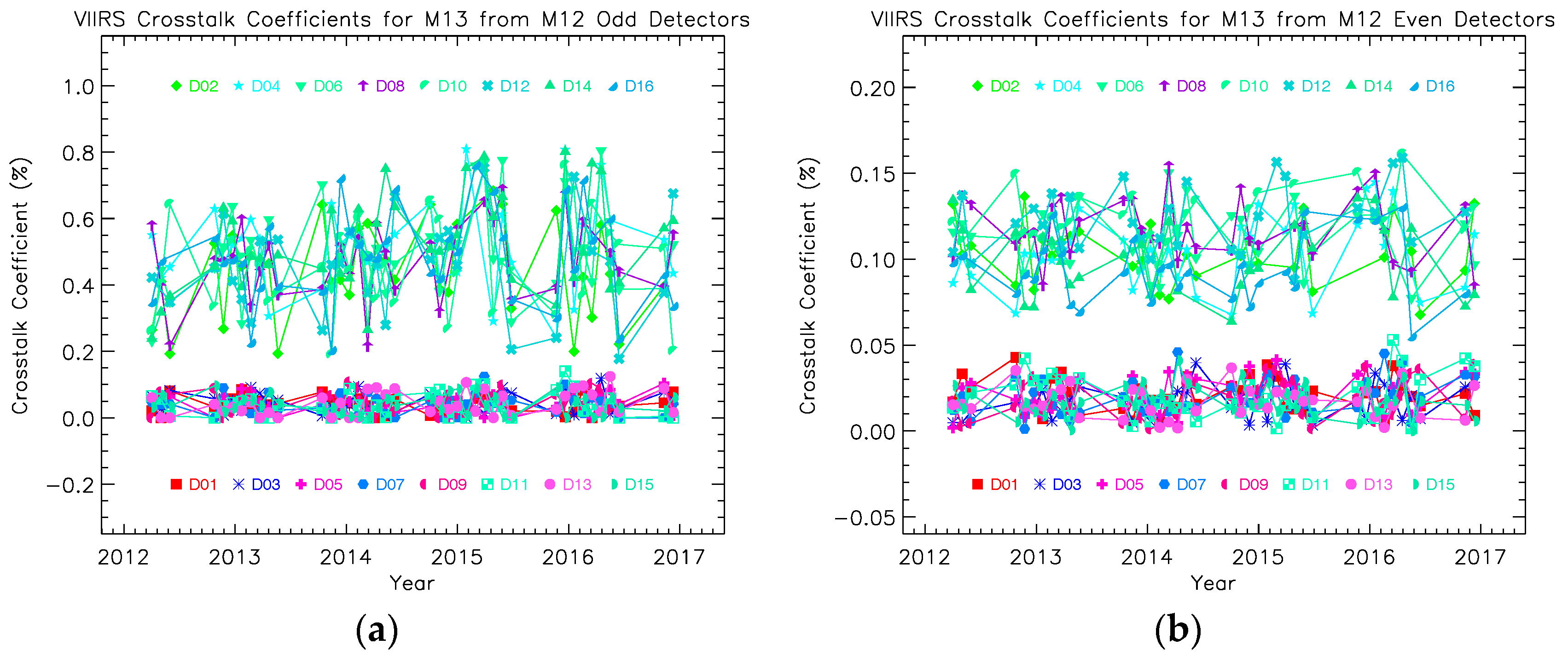
Figure 10.
SNPP VIIRS Band M16 crosstalk coefficients for sending Band M15: (a) odd detectors and (b) even detectors.
Figure 10.
SNPP VIIRS Band M16 crosstalk coefficients for sending Band M15: (a) odd detectors and (b) even detectors.

Figure 11.
Crosstalk coefficients for SNPP VIIRS Bands M13–M16: (a) from odd detectors of the corresponding sending band, (b) from even detectors of the corresponding sending band, and (c) from all detectors of the corresponding sending band.
Figure 11.
Crosstalk coefficients for SNPP VIIRS Bands M13–M16: (a) from odd detectors of the corresponding sending band, (b) from even detectors of the corresponding sending band, and (c) from all detectors of the corresponding sending band.


Table 1.
Suomi National Polar-orbiting Partnership (SNPP) Visible Infrared Imaging Radiometer Suite (VIIRS) center wavelengths, key specifications, and applications [3,6].
| Band No. | Wavelength (μm) | Horiz Sample Interval (km Downtrack × Crosstrack) at Nadir | Driving EDRs | Number of Gain States | |
|---|---|---|---|---|---|
| VIS/NIR FPA | M1 | 0.41 | 0.742 × 0.259 | Ocean Color, Aerosols | Dual |
| M2 | 0.443 | 0.742 × 0.259 | Ocean Color, Aerosols | Dual | |
| M3 | 0.486 | 0.742 × 0.259 | Ocean Color, Aerosols | Dual | |
| M4 | 0.551 | 0.742 × 0.259 | Ocean Color, Aerosols | Dual | |
| I1 | 0.64 | 0.371 × 0.387 | Imagery | Single | |
| M5 | 0.671 | 0.742 × 0.259 | Ocean Color, Aerosols | Dual | |
| M6 | 0.745 | 0.742 × 0.776 | Atmosperic Coor'n | Single | |
| I2 | 0.865 | 0.371 × 0.387 | NDVI | Single | |
| M7 | 0.862 | 0.742 × 0.259 | Ocean Color, Aerosols | Dual | |
| DNB | 0.7 | 0.742 × 0.742 | Imaegry | Triple | |
| S/MWIR FPA | M8 | 1.24 | 0.742 × 0.776 | Cloud Particle Size | Single |
| M9 | 1.378 | 0.742 × 0.776 | Cirrus/Cloud Cover | Single | |
| I3 | 1.61 | 0.371 × 0.387 | Binary Snow Map | Single | |
| M10 | 1.61 | 0.742 × 0.776 | Snow Fraction | Single | |
| M11 | 2.25 | 0.742 × 0.776 | Clouds | Single | |
| I4 | 3.74 | 0.371 × 0.387 | Imagery Clounds | Single | |
| M12 | 3.7 | 0.742 × 0.776 | SST | Single | |
| M13 | 4.05 | 0.742 × 0.259 | SST, Fires | Dual | |
| LWIR FPA | M14 | 8.55 | 0.742 × 0.776 | Cloud Top Properties | Single |
| M15 | 10.763 | 0.742 × 0.776 | SST | Single | |
| I5 | 11.45 | 0.371 × 0.387 | Clound Imagery | Single | |
| M16 | 12.013 | 0.742 × 0.776 | SST | Single |
© 2017 by the authors. Licensee MDPI, Basel, Switzerland. This article is an open access article distributed under the terms and conditions of the Creative Commons Attribution (CC BY) license (http://creativecommons.org/licenses/by/4.0/).
Share and Cite
MDPI and ACS Style
Sun, J.; Wang, M. Crosstalk Effect in SNPP VIIRS. Remote Sens. 2017, 9, 344. https://doi.org/10.3390/rs9040344
AMA Style
Sun J, Wang M. Crosstalk Effect in SNPP VIIRS. Remote Sensing. 2017; 9(4):344. https://doi.org/10.3390/rs9040344
Chicago/Turabian StyleSun, Junqiang, and Menghua Wang. 2017. "Crosstalk Effect in SNPP VIIRS" Remote Sensing 9, no. 4: 344. https://doi.org/10.3390/rs9040344
Note that from the first issue of 2016, this journal uses article numbers instead of page numbers. See further details here.