Article

Circuit Simulation Considering Electrical Coupling in Monolithic 3D Logics with Junctionless FETs

1
Department of Electrical, Electronic and Control Engineering and IITC, Hankyong National University, 327 Jungang-ro, Anseong-si, Gyenggi-do 17579, Korea
2
Group for Smart energy Nano Convergence, Korea Institute of Industrial Technology, 6, Cheomdangwagi-ro 208 beon-gil, Buk-gu, Gwangju 61012, Korea
*
Author to whom correspondence should be addressed.
Micromachines 2020, 11(10), 887; https://doi.org/10.3390/mi11100887
Submission received: 3 August 2020 / Revised: 20 September 2020 / Accepted: 20 September 2020 / Published: 24 September 2020
(This article belongs to the Section E:Engineering and Technology)

Abstract

:
The junctionless field-effect transistor (JLFET) compact model using the model parameters extracted from the LETI-UTSOI (version 2.1) model was proposed to perform circuit simulation considering the electrical coupling between the stacked JLFETs of a monolithic 3D integrated circuit (M3DIC) composed of JLFETs (M3DIC-JLFET). We validated the model by extracting the model parameters and comparing the simulation results of the technology computer-aided design and the Synopsys HSPICE circuit simulator. The performance of the M3DIC-JLFET was compared with that of the M3DIC composed of MOSFETs (M3DIC-MOSFET). The performance of a fan-out-3 ring oscillator with M3DIC-JLFET varied by less than 3% compared to that with M3DIC-MOSFET. The performances of ring oscillators of M3DIC-JLFET and M3DIC-MOSFET were almost the same. We simulated the performances of M3DICs such as an inverter, a NAND, a NOR, a 2 × 1 multiplexer, and a D flip-flop. The overall performance of the M3DIC-MOSFET was slightly better than that of the M3DIC-JLFET.

1. Introduction

Monolithic 3-dimensional integration (M3DI) refers to a 3D integration scheme of sequentially manufacturing and stacking devices [1,2,3]. M3DI has been studied extensively as an alternative to improve semiconductor performance in a region where the scale-down limit of a semiconductor device is approaching. In memories (e.g., NAND flash and dynamic random-access memory) and sensors (e.g., 3D heterogeneous integration), the sequential stacking M3DI method has already been applied instead of the through-silicon via method [4,5,6,7]. In addition, studies have reported that the performance of electrical coupling improves when the inter-layer dielectric (ILD) thickness of the M3D complementary metal-oxide-semiconductor logic is less than 50 nm [8]. M3DI in terms of logic has the potential to enhance chip performance, interconnect delay, device density, and frequency bandwidth without requiring the further lateral scaling of the device [9]. Owing to the process for device stacking sequentially on a single wafer, the previous and next tiers have significant limitations in the process thermal budget for device quality [10]. Compared to the conventional standard process, low-temperature processes using approximately 650 °C have been developed, improving the performance of M3DI [11,12,13]. Currently, most M3DI devices have been researched based on metal-oxide-semiconductor field-effect transistors (MOSFETs) that use Si, Ge, and III-V materials [14,15,16,17]. For the majority of MOSFETs, a thermal budget is required for dopant activation after the implantation process; however, there are physical limitations for using these as low-power devices. For junctionless field-effect transistors (JLFETs), it is possible to use the MOSFET process as it has a junctionless structure. This means that dopant activation is not required, unlike in MOSFETs. JLFETs are advantageous for scale-down, surface mobility degradation, and short-channel effects [18]. A new circuit simulation model has been proposed in which the M3DIC composed of MOSFETs (M3DIC-MOSFETs) reflect direct current (DC)/alternating current (AC) and transient inter-layer electrical coupling [19]. However, owing to the absence of a JLFET compact model that considers electrical coupling between the tiers for the circuit simulation of M3DI structures, an accurate circuit simulation for M3DICs is not possible [20,21,22,23].
In this study, to extract the parameters of the model for the circuit simulation of the M3DIC-JLFET, a structure of monolithic 3D inverter (M3DINV) with electrical coupling (thickness of ILD, TILD = 10 nm) was constructed and simulated using technology computer-aided design (TCAD). To perform circuit simulation considering the electrical coupling of M3DIC-JLFET, we propose the LETI-UTSOI (version 2.1) model [24,25,26] of the fully-depleted silicon-on-insulator (FD-SOI) MOSFET structure as an alternative to the JLFET compact model and extract the model parameters. The extracted model parameters were verified and compared to the TCAD mixed-mode simulation results (Section 3). Based on the model parameters extracted in Section 3, various logics were simulated, and the performance was compared with that of M3DIC-MOSFETs (Section 4) [27]. Section 5 concludes this study.

2. Structures

Figure 1 shows the schematics of an M3DINV composed of JLFET (M3DINV-JLFET). As shown in Figure 1a, an M3DINV-JLFET consists of n-type and p-type JLFET transistors in the top and bottom tiers, respectively. The doping of the JLFET’s source/drain, lightly-doped drain (LDD), and the channel are 1020, 1020, and 1019 cm−3, respectively. The JLFET was simulated at the gate length (Lg), gate oxide film (Tox), silicon thickness (Tsi), and ILD thickness (TILD) at 30, 1, 6 m, and 10 nm, respectively. The gate oxide, ILD, and box were composed of SiO2.
In reference data simulation, a device simulator, ATLAS [28], by SILVACO was used. Table 1 shows the models, methods, and work functions used in the TCAD simulation. The models used for the device simulation were CVT, SRH, BGN, AUGER, and FERMI. The methods used for device simulation were NEWTON and GUMMEL. The gate work functions of the n-type and p-type JLFETs were 5.06 and 4.41 eV, respectively.

3. Parameter Extraction

Figure 2 shows the Simulation Program with Integrated Circuit Emphasis (SPICE) model parameter extraction process used in this study. Through the process flow, model parameters were extracted by comparing them with the reference data. First, parameter initialization was performed, and the threshold voltage (Vt) roll-off and subthreshold swing (SS) degradation parameters were extracted. Next, the mobility and series resistance parameters, velocity saturation, drain-induced barrier lowering (DIBL), and channel length modulation (CLM) parameters were extracted. The process was repeated until the parameters were completely extracted. When the DC parameter extraction was complete, the output conductance parameters were extracted. Finally, the back gate effect parameters were extracted.
Figure 3 shows the current-voltage characteristics with the TCAD and HSPICE simulation results of the bottom p-type JLFET. Based on the driving voltage of the inverter, the gate voltage and the drain voltage were verified up to 1 V. Figure 3a shows the drain current-gate voltage (IpdsVpgs) characteristics at Vpds (−0.2, −0.6, and −1 V) and Vsub = 0 V. Figure 3b shows the IpdsVpds characteristics at Vpgs (−0.2, −0.6, and −1 V) and Vsub = 0 V. The HSPICE results match the TCAD results within 10% error.
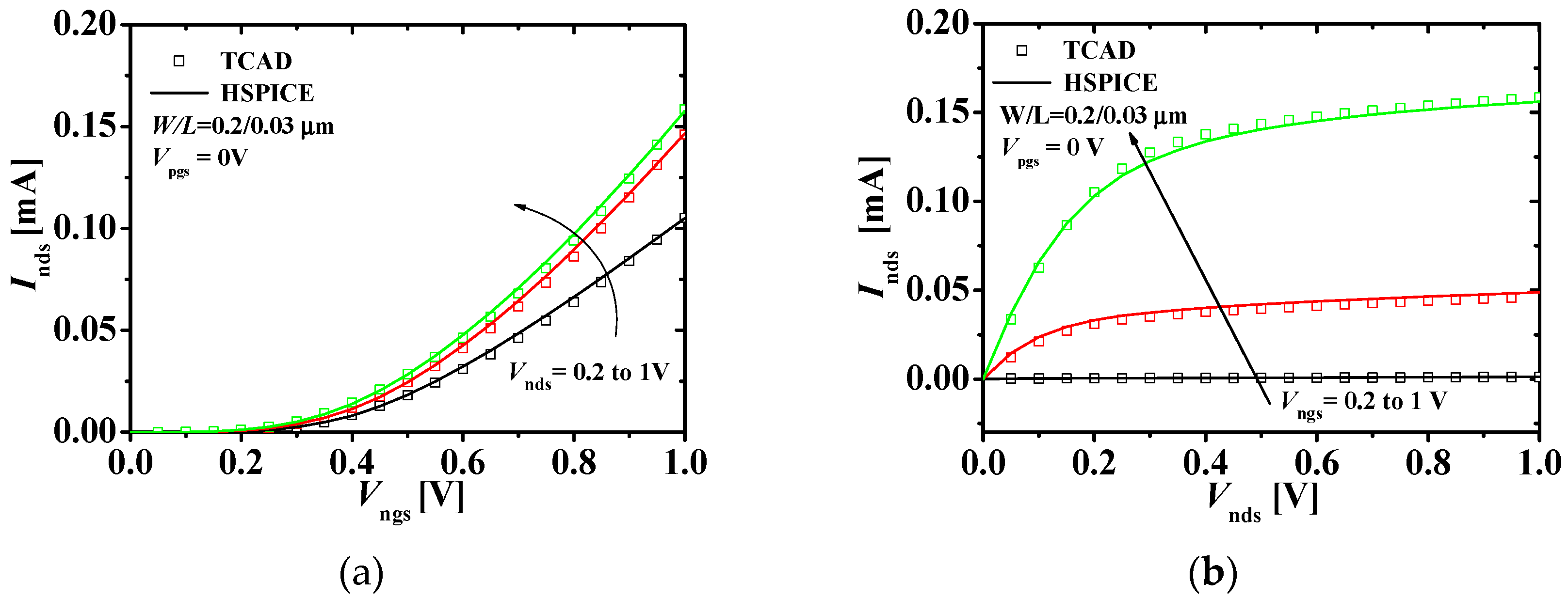
Figure 4 shows the current-voltage characteristics with the TCAD and HSPICE simulation results of the top n-type JLFET. Figure 4a shows the drain current–gate voltage (IndsVngs) characteristics at Vnds (0.2, 0.6, and 1 V) and Vpgs = 0 V. Figure 4b shows the IndsVnds characteristics at Vngs (0.2, 0.6, and 1 V) and Vpgs = 0 V. The HSPICE results match the TCAD results within 10% error.
Figure 5a shows the IndsVngs characteristics at Vpgs (0, 0.5, and 1 V) and Vnds = 1 V. Figure 5b shows the IndsVnds characteristics at Vngs (0.2, 0.6, and 1 V) and Vpgs = Vngs. The HSPICE results match the TCAD results within 10% error. This shows that the top n-type JLFET reflects the dependence on the back-gate (gate of the p-type JLFET) bias well. When a voltage is applied to the gate of the bottom p-type JLFET which can operate as a back-gate in M3DINV with a very thin ILD of TILD = 10 nm, it affects the current of the top n-type JLFET by the threshold voltage shifts.
Figure 6 shows the transconductance-voltage characteristics of the p-type and n-type JLFET. Figure 6a shows the transconductance-gate voltage (gmVpgs) characteristics of the bottom p-type JLFET at Vpds (−0.2, −0.6, and −1 V). Figure 6b shows the transconductance-gate voltage (gmVngs) characteristics of the top n-type JLFET at Vpds (=0.2, 0.6, and 1 V). We observed a minor mismatch at high gate source voltage values. However, the HSPICE simulation results matched the TCAD results overall within 10% error.
Figure 7 compares the capacitance-voltage characteristics of the p-type and n-type JLFET. Figure 7a shows the gate capacitance-gate voltage (CpgpgVpgs) characteristics of the bottom p-type JLFET at Vpds (−0.2, −0.6, and −1 V). Figure 6b shows the gate capacitance-gate voltage (CngngVngs) characteristics of the top n-type JLFET at Vpds (0.2, 0.6, and 1 V). The HSPICE simulation results match the TCAD results.
Following the model parameter extraction process flow, we extracted the parameters of the bottom p-type and top n-type JLFET using the LETI-UTSOI model, as shown in Table 2.
Figure 8a shows an equivalent circuit of the M3DINV composed of the top n-type and bottom p-type JLFETs in series. The LETI-UTSOI model was applied to both the JLFETs. The input voltage (VIN = Vpg = Vng) of M3DINV was applied to the gates of the n-type and p-type JLFETs. The driving voltage (VDD) was applied to the source of the p-type JLFET, and the source of the n-type JLFET was connected to the ground. The output voltage (VOUT = Vpd = Vnd) was the drain voltage of the n-type and p-type JLFET. Figure 8b compares the voltage transfer characteristics (VTC) on the M3DINV-JLFET, as shown in Figure 8a. The HSPICE simulation results match the TCAD results overall within 10% error.
Figure 9 shows the transient response of the M3DINV-JLFET. Black squares (and solid lines) and red circles (and dot lines) denote the input voltages VIN and the output voltages VOUT of the M3DINV, respectively. Load capacitance CL = 1 fF was used. The HSPICE simulation results match the TCAD results overall within 10% error.

4. Circuit Simulation and Discussion

Table 3 shows the power consumption and performance of a fan-out-3 (FO3) ring oscillator built using M3DINV-JLFETs. The M3DINV-JLFETs were compared with the M3DINV-MOSFETs. The power consumption, frequency, and delay per stage of the ring oscillators with 3, 19, and 101 stages of the M3DINV-JLFETs varied less than 3% from those of the M3DINV-MOSFETs. However, the performances of the M3DINV-MOSFET and M3DINV-JLFET were approximately the same.
Table 4 summarizes the performance comparison of M3DIC-JLFETs and M3DIC-MOSFETs. M3DICs such as the INV, NAND, NOR, 2 × 1 multiplexer (MUX) [29], D flip-flop (D-FF) [30], and 6T SRAM [31] were simulated. Their performances were compared in terms of their average static power, average dynamic power, and average delay. The static power of M3DINV-JLFETs increased approximately 600% more than the power of the M3DIC-MOSFETs. Electrical coupling by the gate of the bottom transistor increases the leakage current of the top transistor, resulting in an increase in static power. M3DIC-JLFETs have more leakage current changes due to electrical coupling than M3DIC-MOSFETs. The dynamic power of M3DINV-JLFETs increased approximately 34.5% more than the power of M3DIC-MOSFETs. The average propagation delay of the M3DINV-JLFETs increased approximately 17.5% compared to that of M3DIC-MOSFETs. Because the load cap of M3DIC-JLFETs is larger than that of the M3DIC-MOSFETs due to the electric coupling, the dynamic power and delay of the M3DIC-JLFETs are larger than those of the M3DIC-MOSFETs.

5. Conclusions

In this study, we propose to use the LETI-UTSOI (version 2.1) model as an alternative to the JLFET compact model to perform circuit simulation considering the electrical coupling of M3DIC- JLFET. Comparing the simulation results of TCAD and HSPICE, the parameters of the proposed model were extracted and the DC, AC, and transient response characteristics were verified. Although the LETI-UTSOI model of the FD-SOI MOSFET structure is used as an alternative to the JLFET compact model, it was confirmed that circuit simulation considering electrical coupling between vertically stacked JLFETs is possible. Because of the various circuit simulations, the overall performance of the M3DIC-MOSFETs was slightly higher than that of the M3DIC-JLFETs. However, considering the ease of processing, miniaturization, and advantages of M3DI, the applicability of M3DIC-JLFET is higher.

Author Contributions

Conceptualization, T.J.A. and Y.S.Y.; methodology, T.J.A. and Y.S.Y.; investigation, T.J.A. and Y.S.Y.; data curation, T.J.A.; writing—original draft preparation, T.J.A.; writing—review and editing, T.J.A. and Y.S.Y.; supervision, Y.S.Y.; project administration, Y.S.Y.; funding acquisition, Y.S.Y. All authors have read and agreed to the published version of the manuscript.

Funding

This research was supported by the Basic Science Research Program through NRF of Korea funded by the Ministry of Education (NRF-2019R1A2C1085295).

Acknowledgments

This work was supported by IDEC (EDA tool).

Conflicts of Interest

The authors declare no conflict of interest.

References

  1. Claverlier, L.; Deguet, C.; di Cioccio, L.; Augendre, E.; Brugere, A.; Gueguen, P.; Tiec, Y.L.; Moriceau, H.; Rabarot, M.; Signamarcheix, T.; et al. Engineered substrates for future More Moore and More than Moore integrated devices. In Proceedings of the 2010 IEEE International Electron Devices Meeting (IEDM), San Francisco, CA, USA, 6–8 December 2010; pp. 261–264. [Google Scholar] [CrossRef]
  2. Lim, S.K. Bringing 3D ICs to aerospace: Needs for design tools and methodologies. J. Lnf. Commun. Converg. Eng. 2017, 15, 117–122. [Google Scholar] [CrossRef]
  3. Wong, S.; El-Gamal, A.; Griffin, P.; Nishi, Y.; Pease, F.; Plummer, J. Monolithic 3D Integrated Circuits. In Proceedings of the International Symposium on VLSI Technology, Systems and Applications (VLSI-TSA), Hsinchu, Taiwan, 23–25 April 2007; pp. 1–4. [Google Scholar] [CrossRef]
  4. Park, K.T.; Nam, S.W.; Kim, D.H.; Kwak, P.S.; Lee, D.S.; Choi, Y.H.; Choi, M.H.; Kwak, D.H.; Kim, D.H.; Kim, M.S.; et al. Three-dimensional 128 Gb MLC vertical nand flash memory with 24-WL stacked layers and 50 MB/s high-speed programming. IEEE J. Solid State Circuits. 2015, 50, 204–213. [Google Scholar] [CrossRef]
  5. Shen, C.-H.; Shieh, J.-M.; Wu, T.-T.; Huang, W.-H.; Yang, C.-C.; Wan, C.-J.; Lin, C.-D.; Wang, H.-H.; Chen, B.-Y.; Huang, G.-W.; et al. Monolithic 3D chip integrated with 500ns NVM, 3ps logic circuits and SRAM. In Proceedings of the 2013 IEEE International Electron Devices Meeting, Washington, DC, USA, 9–11 December 2013; pp. 931–934. [Google Scholar] [CrossRef]
  6. Batude, P.; Ernst, T.; Arcamone, J.; Arndt, G.; Coudrain, P.; Gaillardon, P.-E. 3-D sequential integration: A key enabling technology for heterogeneous co-integration of new function with CMOS. IEEE J. Emerg. Sel. Top. Circuits Syst. 2012, 2, 714–722. [Google Scholar] [CrossRef]
  7. Sachid, A.B.; Tosun, M.; Desai, S.B.; Hsu, C.-Y.; Lien, D.-H.; Madhvapathy, S.R.; Chen, Y.-Z.; Hettick, M.; Kang, J.S.; Zeng, Y.; et al. Monolithic 3D CMOS using layered semiconductors. Adv. Mater. 2016, 28, 2547–2554. [Google Scholar] [CrossRef] [PubMed]
  8. Fan, M.-L.; Hu, V.P.-H.; Chen, Y.-N.; Su, P.; Chuang, C.-T. Investigation and optimization of monolithic 3D logic circuits and SRAM cells considering interlayer coupling. In Proceedings of the 2014 IEEE International Symposium on Circuits and Systems (ISCAS), Melbourne, VIC, Australia, 1–5 June 2014; pp. 1130–1133. [Google Scholar] [CrossRef]
  9. Turkylimaz, O.; Cibrario, G.; Rozeau, O.; Batude, P.; Clermidy, F. 3D FPGA using high-density interconnect Monolithic Integration. In Proceedings of the 2014 Design, Automation & Test in Europe Conference & Exhibition (DATE), Dresden, Germany, 24–28 March 2014; pp. 1–4. [Google Scholar] [CrossRef]
  10. Vinet, M.; Batude, P.; Tabone, C.; Previtali, B.; LeRoyer, C.; Pouydebasque, A.; Claverlier, L.; Valentian, A.; Thomas, O.; Michaud, S.; et al. 3D monolithic integration: Technological challenges and electrical results. Microelectron. Eng. 2010, 88, 331–335. [Google Scholar] [CrossRef]
  11. Santos, C.; Vivet, P.; Thuries, S.; Billoint, O.; Colonna, J.-P.; Coudrain, P.; Wang, L. Thermal performance of CoolCubeTM monolithic and TSV-based 3D integration processes. In Proceedings of the IEEE International 3D Systems Integration Conference (3DIC), San Francisco, CA, USA, 8–11 November 2016; pp. 1–5. [Google Scholar] [CrossRef]
  12. Llorente, C.D.; Royer, C.L.; Batude, P.; Fenouillet-Beranger, C.; Martinie, S.; Lu, C.-M.V.; Allain, F.; Colinge, J.-P.; Cristoloveanu, S.; Ghibaudo, G.; et al. New insights on SOI tunnel FETs with low-temperature process flow for CoolCubeTM integration. Solid State Electron. 2018, 144, 78–85. [Google Scholar] [CrossRef]
  13. Broard, M.; Boumchedda, R.; Noel, J.P.; Akyel, K.C.; Giraud, B.; Beigne, E.; Turgis, D.; Thuries, S.; Berhault, G.; Billoint, O. High density SRAM bitcell architecture in 3D sequential CoolCubeTM 14nm technology. In Proceedings of the 2016 IEEE SOI-3D-Subthreshold Microelectronics Technology Unified Conference (S3S), Burlingame, CA, USA, 10–13 October 2016; pp. 1–3. [Google Scholar] [CrossRef]
  14. Kim, S.H.; Kim, S.K.; Shim, J.P.; Geum, D.M.; Ju, G.W.; Kim, H.S.; Lim, H.J.; Lim, H.R.; Han, J.H.; Lee, S.B.; et al. Heterogeneous Integration Toward a Monolithic 3-D Chip Enabled by III–V and Ge Materials. IEEE J. Electron Devices Soc. 2018, 6, 579–587. [Google Scholar] [CrossRef]
  15. Abedin, A.; Zurauskaite, L.; Asadollahi, A.; Garidis, K.; Jayakumar, G.; Malm, G.; Hellstrom, P.-E.; Ostling, M. Germanium on Insulator Fabrication for Monolithic 3-D Integration. IEEE J. Electron Devices Soc. 2018, 6, 588–593. [Google Scholar] [CrossRef]
  16. Kim, S.H.; Kim, S.K.; Han, J.H.; Geum, D.M.; Shim, J.P.; Lee, S.B.; Kim, H.S.; Ju, G.W.; Song, J.D.; Alam, M.A.; et al. Highly Stable Self-Aligned Ni-InGaAs and Non-Self-Aligned Mo Contact for Monolithic 3-D Integration of InGaAs MOSFETs. IEEE J. Electron Devices Soc. 2019, 7, 869–877. [Google Scholar] [CrossRef]
  17. Kanhaiya, P.S.; Stein, Y.; Lu, W.; Alamo, J.A.; Shulaker, M.M. X3D: Heterogeneous Monolithic 3D Integration of “X” (Arbitrary) Nanowires: Silicon, III–V, and Carbon Nanotubes. IEEE Trans. Nanotechnol. 2019, 18, 270–273. [Google Scholar] [CrossRef]
  18. Hsieh, D.-R.; Lin, J.-Y.; Chao, T.-S. High-Performance Pi-Gate Poly-Si Junctionless and Inversion Mode FET. IEEE Trans. Electron Devices 2016, 63, 4179–4184. [Google Scholar] [CrossRef]
  19. Ahn, T.J.; Perumal, R.; Lim, S.K.; Yu, Y.S. Parameter Extraction and Power/Performance Analysis of Monolithic 3-D Inverter (M3INV). IEEE Trans. Electron Devices 2019, 66, 1006–1011. [Google Scholar] [CrossRef]
  20. Jazaeri, F.; Sallese, J.-M. Modeling Nanowire and Double-Gate Junctionless Field-Effect Transistors; Cambridge University Press: Cambridge, UK, 2018. [Google Scholar]
  21. Sallese, J.-M.; Chevillon, N.; Lallement, C.; Iniguez, B. Charge-Based Modeling of Junctionless Double-Gate Field-Effect Transistors. IEEE Trans. Electron Devices 2011, 58, 2628–2637. [Google Scholar] [CrossRef]
  22. Rassekh, A.; Jazaeri, F.; Fathipour, M.; Sallese, J.-M. Modeling Interface Charge Traps in Junctionless FETs, Including Temperature Effects. IEEE Trans. Electron Devices 2019, 66, 4653–4659. [Google Scholar] [CrossRef] [Green Version]
  23. Yu, Y.S. A Unified Analytical Current Model for N- and P-Type Accumulation-Mode (Junctionless) Surrounding-Gate Nanowire FETs. IEEE Trans. Electron Devices 2014, 61, 3007–3010. [Google Scholar] [CrossRef]
  24. Rozeau, O.; Jaud, M.-A.; Poiroux, T.; Benosman, M. UTSOI Model 1.1.3. Laboratoire d’Électronique et de Technologie de l’Information (Leti). Available online: http://www-leti.cea.fr (accessed on 25 May 2012).
  25. Poiroux, T.; Rozeau, O.; Scheer, P.; Martinie, S.; Jaud, M.A.; Minondo, M.; Juge, A.; Barbe, J.C.; Vinet, M. Leti-UTSOI2.1: A Compact Model for UTBB-FDSOI Technologies—Part I: Interface Potentials Analytical Model. IEEE Trans. Electron Devices 2015, 62, 2751–2759. [Google Scholar] [CrossRef]
  26. Poiroux, T.; Rozeau, O.; Scheer, P.; Martinie, S.; Jaud, M.A.; Minondo, M.; Juge, A.; Barbe, J.C.; Vinet, M. Leti-UTSOI2.1: A Compact Model for UTBB-FDSOI Technologies—Part II: DC and AC Model Description. IEEE Trans. Electron Devices 2015, 62, 2760–2768. [Google Scholar] [CrossRef]
  27. Ahn, T.J.; Choi, B.H.; Lim, S.K.; Yu, Y.S. Electrical Coupling and Simulation of Monolithic 3D Logic Circuits and Static Random Access Memory. Micromachines 2019, 10, 637. [Google Scholar] [CrossRef] [PubMed] [Green Version]
  28. Silvaco Int. ATLAS Ver. 5. 20. 2. R Manual; Silvaco Int.: Santa Clara, CA, USA, 2015. [Google Scholar]
  29. Rani, T.E.; Rani, M.A.; Rao, R. AREA optimized low power arithmetic and logic unit. In Proceedings of the International Conference on Electronics Computer Technology, Kanyakumari, India, 8–10 April 2011; pp. 224–228. [Google Scholar] [CrossRef]
  30. Nasrollahpour, M.; Sreekumar, R.; Hajilou, F.; Aldacher, M.; Hamedi-Hagh, S. Low-power bluetooth receiver front end design with oscillator leakage reduction technique. J. Low Power Electron. 2018, 14, 179–184. [Google Scholar] [CrossRef]
  31. Arandilla, C.D.C.; Alvarez, A.B.; Roque, C.R.K. Static noise margin of 6T SRAM cell in 90-nm CMOS. In Proceedings of the UkSim 13th International Conference on Computer Modelling and Simulation, Cambridge, UK, 30 March–1 April 2011; pp. 534–539. [Google Scholar] [CrossRef]
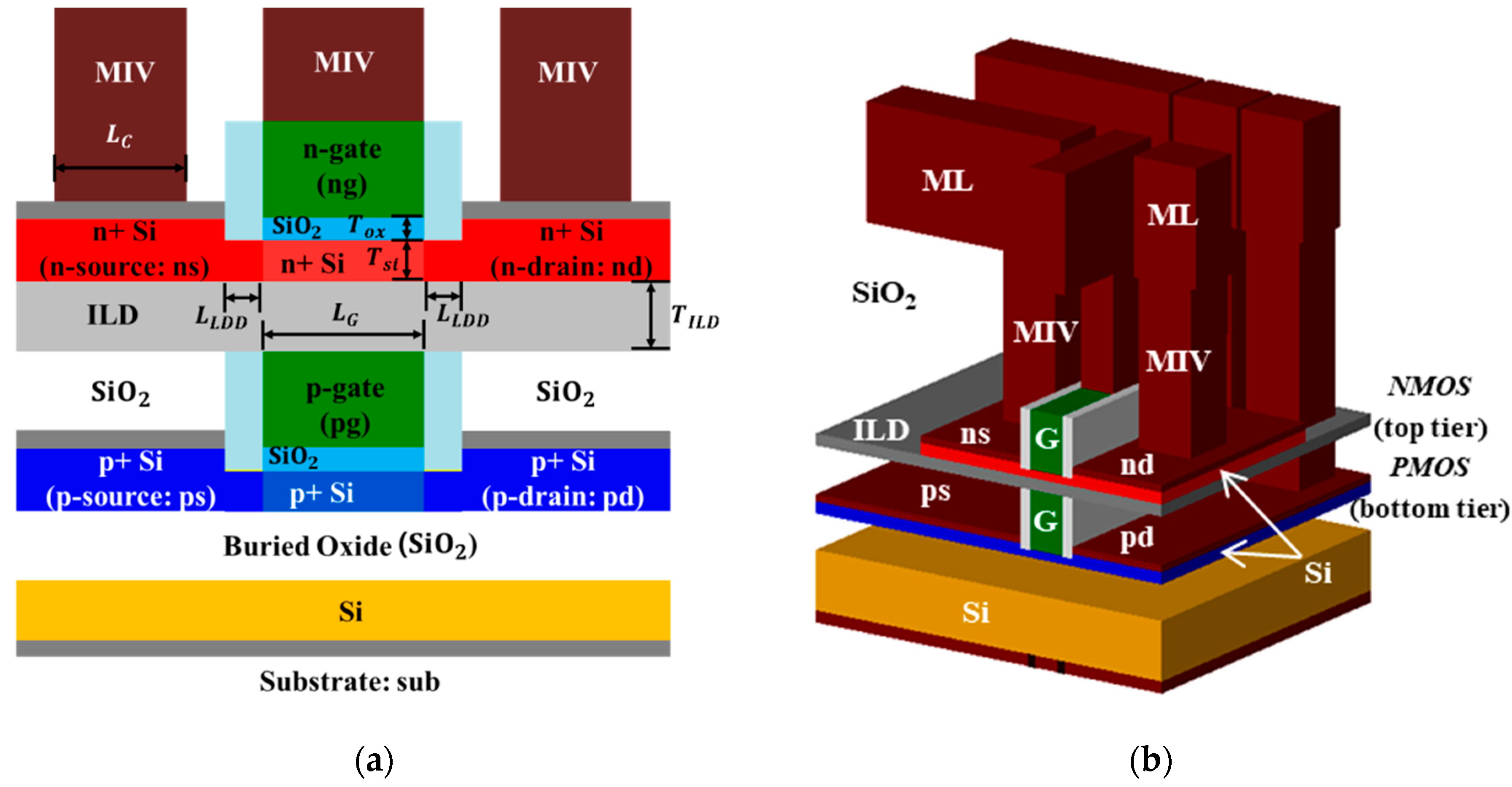
Figure 1. Schematics of two types of M3DINVs composed of JLFET structures: (a) 2D cross section; (b) 3D structure of M3DINV.
Micromachines 11 00887 g001
Figure 2. SPICE model’s parameter extraction process flow.
Micromachines 11 00887 g002
Figure 3. Current-voltage characteristics of the bottom p-type JLFET: (a) |Ipds|−Vpgs characteristics at different values of Vpdss; (b) |Ipds|−Vpds characteristics at different values of Vpgss (squares and lines denote the TCAD and HSPICE simulation results, respectively; W/L = 0.29/0.03 μm)
Micromachines 11 00887 g003
Figure 4. Current-voltage characteristics of the top n-type JLFET: (a) IndsVngs characteristics at different values of Vndss; (b) IndsVnds characteristics at different values of Vngss at Vpgs = 0 V (squares and lines denote the TCAD and HSPICE simulation results, respectively; W/L = 0.2/0.03 μm).
Micromachines 11 00887 g004
Figure 5. Current-voltage characteristics of the top n-type JLFET: (a) IndsVngs characteristics at different values of Vpgss at Vnds = 0 V; (b) IndsVnds characteristics at different values of Vngs s at Vpgs = Vngs (squares and lines denote the TCAD and HSPICE simulation results, respectively; W/L = 0.2/0.03 μm).
Micromachines 11 00887 g005
Figure 6. Transconductance-voltage characteristics at different values of Vdss: (a) the p-type JLFET; and (b) the n-type JLFET (the squares and lines denote the TCAD and HSPICE simulation results, respectively).
Micromachines 11 00887 g006
Figure 7. (a) Gate capacitance (Cpgpg) of the bottom p-type JLFET at different values of Vpdss; (b) gate capacitance (Cngng) of the top n-type JLFET at different values of Vnds s and Vpgs s = 0 V (symbols and lines denote the TCAD and HSPICE simulation results, respectively).
Micromachines 11 00887 g007
Figure 8. (a) Equivalent circuit of M3DINV-JLFET; (b) VTC of M3DINV-JLFET; VSS = 0 V and VDD = 1 V (the symbols and lines denote the TCAD mixed-mode and HSPICE simulation results, respectively; VIN = Vpg = Vng, VOUT = Vpd = Vnd, and Vsub = VDD).
Micromachines 11 00887 g008
Figure 9. Transient response of the M3DINV-JLFET (symbols and lines denote the TCAD mixed-mode and HSPICE simulation results, respectively; load capacitance CL = 1 fF).
Micromachines 11 00887 g009
Table 1. Descriptions and dimensions of the models/parameters used in the TCAD simulation.
Models/ParametersDescriptionValue/Unit
CVTLombardi model and complete mobility model including the doping density N, temperature T, and transverse electric field E//
SRHShockley-Read-Hall recombination model
BGNBand gap narrowing model
AUGERAuger recombination model
FERMIFermi-Dirac carrier statistics
NEWTONNewton method which solves a linearized version of the entire nonlinear algebraic system
GUMMELGUMMEL method, which solves a sequence of relatively small linear subproblems
ΦNGate work function of N-type JLFET5.06 eV
ΦPGate work function of P-type JLFET4.41 eV
Table 2. Summary of the extracted parameters of the LETI-UTSOI model for the bottom p-type and top n-type JLFET.
ParameterUnitDescriptionValue
P-TypeN-Type
DLQmEffective channel length offset
for C−V (capacitance −voltage)
2 × 10−81 × 10−8
VBFOVGeometry-independent flat-band voltage0.29−0.28
CICOGeometry-independent part of substrate bias dependence factor of interface coupling0.653
PSCELLength dependence of
short channel effect above threshold
0.50.1
CFLV−1Length dependence of DIBL (Drain-Induced Barrier Lowering) parameter2.72
UOm2/V/sZero-field mobility 6.5 × 10−31.75 × 10−2
MUEOm/VMobility reduction coefficient11
THEMUOMobility reduction exponent 1.221.8
RSGOGate-bias dependence of RS (Resistance)21
THESATOV−1Geometry-independent Velocity saturation parameter 1.82.7
THESATBOV−1Substrate bias dependence of velocity saturation0.10.28
FETAOEffective field parameter0−3
AXOGeometry-independent of linear/saturation transition factor1.61.6
ALPL1Length dependence of CLM pre-factor ALP0.00050.00001
VPOVCLM logarithm dependence factor0.040.04
CFRWFOuter fringe capacitance2 × 10−162 × 10−16
Table 3. Fanout-3 (FO3) ring oscillator performance using M3DINV models (MOSFET and JLFET).
StagesPower [μW]Frequency [GHz]Delay Per Stage [ps]
MOSFETJLFETMOSFETJLFETMOSFETJLFET
3281275 (−2.13%)18.718.18 (−2.78%)9.049.165 (1.38%)
19279277 (−0.71%)2.882.86 (−0.69%)9.169.18 (0.2%)
101281283 (0.71%)0.520.52 (0%)9.289.35 (0.7%)
Table 4. Performance comparison of the M3DIC-MOSFETs and M3DIC-JLFETs.
PerformancesM3DIC-MOSFET [27]M3DIC-JLFET
INVNANDNORMUXD-FFSRAMINVNANDNORMUXD-FFSRAM
Average static power [nW]4.899.846.2311.815.44.310.6
(116.7%)
78
(692%)
54.5
(774%)
104.7
(787%)
123.2
(700%)
20.3
(372%)
Average dynamic power [μW]9.8521.116.637.741.92016.5
(67.5%)
29.3
(38.8%)
20.7
(24.6%)
46.6
(23.6%)
47.8
(14%)
28.2
(41%)
Average delay [ps]4.174.615.654.4110.258.14.65
(11.5%)
6.1
(32.3%)
7.31
(29.3%)
4.72
(7%)
11.9
(16%)
8.85
(9.25%)