Article

L-Shaped Slot-Loaded Stepped-Impedance Microstrip Structure UWB Antenna

1
College of Information Engineering, Jimei University, Xiamen 361021, China
2
College of IoT Engineering, Jiangnan University, Wuxi 214122, China
*
Author to whom correspondence should be addressed.
Micromachines 2020, 11(9), 828; https://doi.org/10.3390/mi11090828
Submission received: 8 August 2020 / Revised: 27 August 2020 / Accepted: 31 August 2020 / Published: 31 August 2020
(This article belongs to the Special Issue Next Generation RFID Transponders)

Abstract

:
A stepped planar microstrip structure is proposed and demonstrated as a candidate of the ultra-wideband (UWB) antenna in the paper. In the structure, two L-shaped slots are introduced into the rectangular microstrip patch to broaden the current path at both edges of the radiating patch. The impedance bandwidth of the antenna can be extended by using the stepped impedance resonator (SIR) structure at one end of the radiation patch and connecting with the feed line. The symmetrical two I-shaped slots are loaded on the SIR microstrip to improve in-band performance and further widen the operating band. The proposed new structure can have an improvement in the in-band characteristics while extending the operating bandwidth. A broadband impedance bandwidth of 2.39 GHz to 13.78 GHz at S11 < −10 dB is demonstrated based on the proposed novel structure. The reflection coefficient and radiation characteristics are characterized in the paper. The tiny antenna, with the benefit of small area 36 mm × 23 mm, shows potential applications in ultra-wideband communication systems, wireless energy harvesting systems, and other wireless systems.

1. Introduction

Ultra-wideband (UWB) technology is widely considered as one of the most potential technologies in the field of wireless communications since the US Federal Communications Commission (FCC) announced that the band of commercial communication applications for ultra-wideband systems is 3.1–10.6 GHz [1,2]. UWB technology is critical in radar [3,4] and communication systems [5,6,7]. In the systems, the UWB antenna is adapted for receiving the UWB signals with many mandatory requirements, including the wide bands, good radiation characteristics, small size, and flexible assembly, etc. Currently, there are several available UWB antennas, including the logarithmic periodic structure and spiral structure UWB antenna [8,9]. The principle of those kinds of UWB antennas is easily understood. In the above antennas, there are always multiple parts integrated into the system, corresponding to the different frequency components. However, the integration would induce the distortion and stretching of the synthesized waveform. To avoid the issue, the UWB antennas with broadband monopole structures and improved Vivaldi antenna are proposed in refs [10,11,12,13], such as roll monopole and cylindrical monopole [10,11,12], as well as the 3D bent structure [13]. Those antennas show wide bandwidth and good radiation characteristics. However, the three-dimensional structure cannot be assembled into the circuit board by the direct printing approach. Recently, the planar microstrip structure UWB antenna with compact size and excellent performance is proposed [14,15,16,17]. The antenna can easily be mass-produced and be assembled on the printed circuit board (PCB), with the additional benefit of low cost. The literature [14,15] has proposed a planar UWB antenna with a monopole structure. But the detailed information on the characterization of the antenna isn’t shown clearly. In ref [16], a UWB and narrow-band converted antenna is proposed, which is composed of the microstrip fold line and two band-pass filters, showing a stable gain and impedance bandwidth. In ref [17], a microstrip elliptical ring dipole antenna is reported. However, the band performance and the size should be optimized furthermore. In refs [18,19,20,21,22,23,24,25,26], the UWB antennas with slot structure are proposed, showing optimized band performance with small size. The literature [25] has proposed a circularly polarized square slot antenna, which generates circularly polarized excitation by embedding L-shaped microstrips of unequal sizes near two diagonal corners in a square slot. The frequency band with reflection coefficient less than −10 dB ranges from 2.8 GHz to 13 GHz, and the impedance bandwidth is 10.2 GHz. The literature [26] proposes an ultra-wideband antenna with a microstrip square ring slot. The antenna feeds by fork like-tuning stub with a good radiation pattern and constant gain in the operating frequency band.
A novel UWB antenna is proposed in the paper. In the antenna, there are two inverted L-shaped slots loaded on the side of the radiating microstrip patch and the other I-shaped slots loaded on the side of the stepped impedance microstrip closing to the feed line. The feed line is connected with the one terminal of the stepped microstrip. The other side of the dielectric layer under the feed line is providing with a ground plane spaced from the radiation patch. The characterization results demonstrate that the novel structure with the reduced area improves the in-band performance of the ultra-wideband antenna and expands the impedance bandwidth.
The organization of this paper is as follows. Firstly, the various structures of UWB antennas are briefly introduced. Furthermore, the UWB antennas with the slot structure are discussed, in which mainly the size reduction and the frequency band expansion are focused on. Then, the main structure of the proposed UWB antenna in the paper is shown. The L-shaped and I-shaped slots are loaded in a radiation patch to expand the bandwidth. The influences of the structure parameters of the antenna on the performance are discussed. The fabrication of the UWB antenna on the RO 4350 is introduced in the following part, with the key results shown, including the voltage standing wave ratio (VSWR), radiation pattern, and gain. The conclusion is summarized in the last part, showing possible application areas of the proposed antenna.

2. Antenna Structure

The antenna structure designed in this paper is shown in Figure 1. The dielectric substrate is Rogers 4350, with the relative dielectric constant 3.66, the loss tangent 0.004, and the thickness h of substrate 0.508 mm. The size of the UWB antenna is 36 mm × 23 mm, which is smaller than the recent reports on the most of ultra-wideband antenna in Table 1 [14,15,16,17,18,19,23,24,25,26]. The feed line is connected with the side of the stepped rectangular microstrip. The radiation microstrip patch near the feed line is loaded by the two L-shaped slot structures on both sides, respectively. A stepped impedance microstrip structure is implemented between the feed line and the radiate microstrip patch, which can improve the impedance characteristics of the antenna. The microstrip patch of the stepped impedance microstrip loaded with axisymmetric I-shaped slots can improve the bandwidth and the performance in-band. A ground plate exists on the back of the dielectric layer, where the feed line is located on the top. A narrow gap is formed between the radiating patch and the feed line.
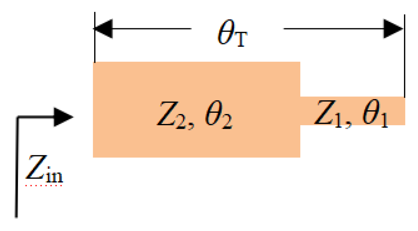
The stepped impedance resonator (SIR) structure has been reported in the design of bandpass filters, duplexers, and metamaterial unit-cell [27,28,29,30]. The SIR is a cascade of high impedance and low impedance transmission lines. The high impedance line acts as a series inductor, and the low impedance line acts as a parallel capacitor. The SIR resonator controls the harmonic frequency corresponding to the frequency response by adjusting the impedance ratio and the length of the resonator to compensate for the unequal phase velocity of the odd mode and even mode. A wider resonance frequency band can be obtained based on the structure. In Figure 2, both terminals are at the open state and are formed by two microstrip transmission lines. The two microstrip transmission lines have different characteristic impedances (Z1 and Z2) with the electrical length θ1 and θ2, respectively. The two microstrip transmission lines have different characteristic impedances and have different electrical lengths, respectively. If the effect of step discontinuity is ignored, the basic resonance condition of SIR can be derived from the input impedance of the opened terminal, which can be written as [31]:
Z in = j Z 2 Z 2 tg θ 2 + Z 1 tg θ 1 Z 2 Z 1 tg θ 1 tg θ 2
According to the resonant conditions, Z in = . The following formula is established.
Z 2 Z 1 tg θ 1 tg θ 2 = 0
The impedance ratio is defined as:
Z 2 Z 1 = k = tg θ 1 tg θ 2
k is the impedance ratio.
It can be seen from Figure 2 that the total electrical length is θ T . The following relationship can be obtained from Equation (2):
tg θ T = ( tg θ 1 + θ 2 ) = tg θ 1 + tg θ 2 1 tg θ 1 tg θ 2 = 1 1 k ( tg θ 1 + tg θ 2 ) = 1 1 k ( tg θ 1 + k tg θ 1 )
When k = 1, it is a uniform impedance transmission line resonator.
To simplify, choose θ 1 = θ 2 = θ 0 . The resonance condition of the fundamental frequency is given by
θ 0 = arctg k
The spurious frequency is f s , and the corresponding θ is θ s . It is obtained from Z in = and Equation (1)
tg θ s =
The first spurious resonance frequency f s is given by [31]
f s f 0 = θ s θ 0
Then
f s = π 2 arctg k f 0
In this paper, the SIR microstrip structure is used as the transition section between the feed line and the radiating patch, which is equivalent to adding a matching network to broaden the operating frequency band. Adjusting the microstrip width of the SIR is equivalent to the adjustment of the impedance ratio. A wideband design is realized by appropriately selecting the physical structure parameters.

3. Simulation Design Analysis

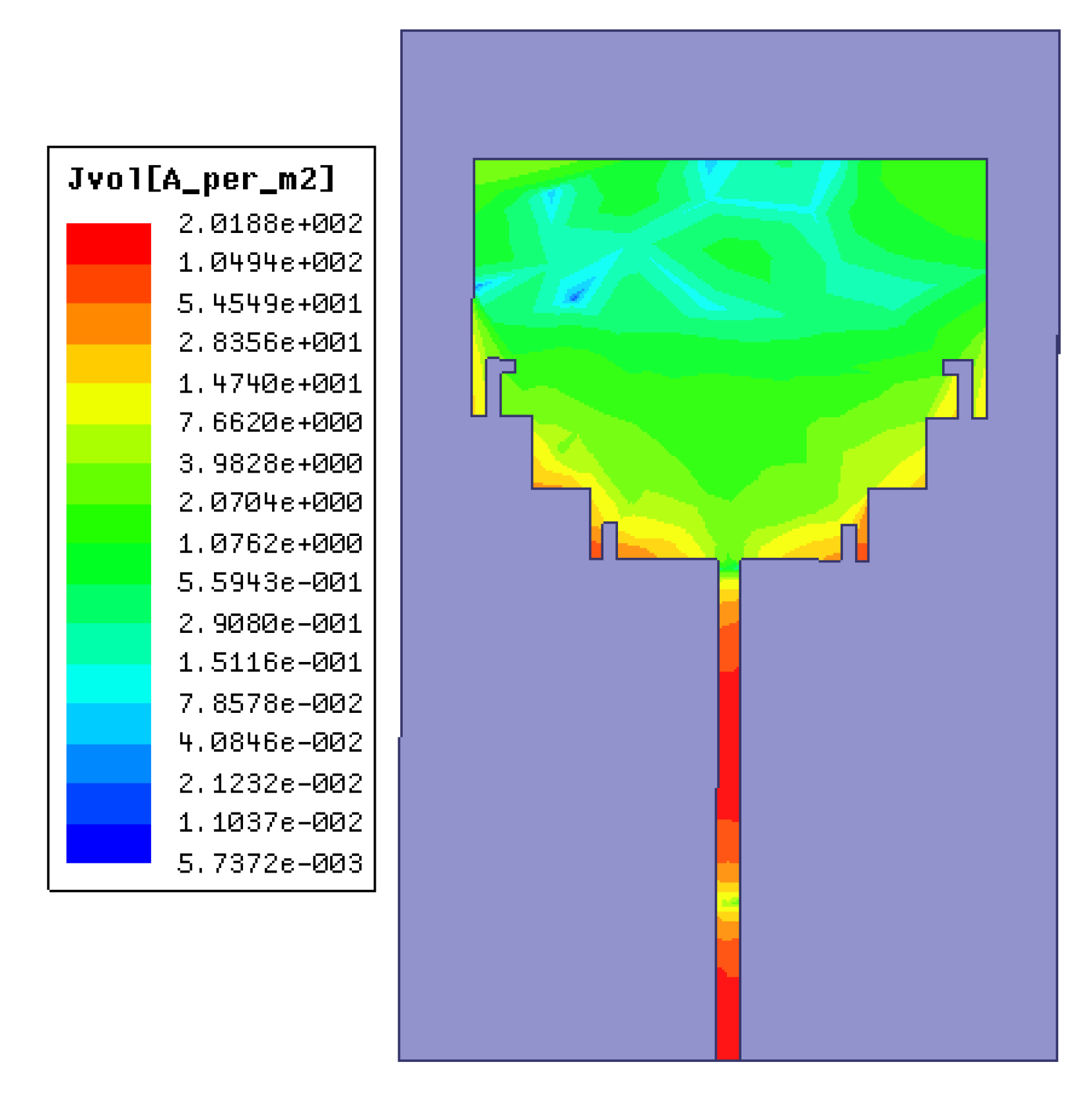
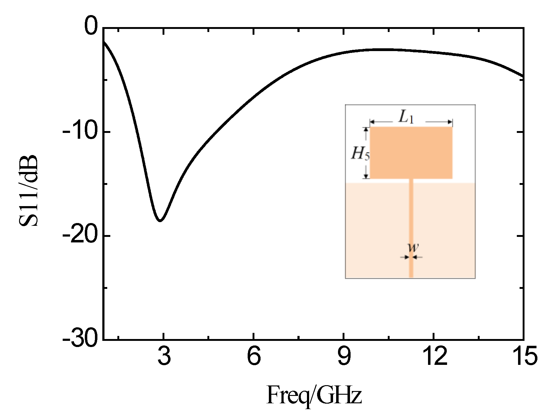
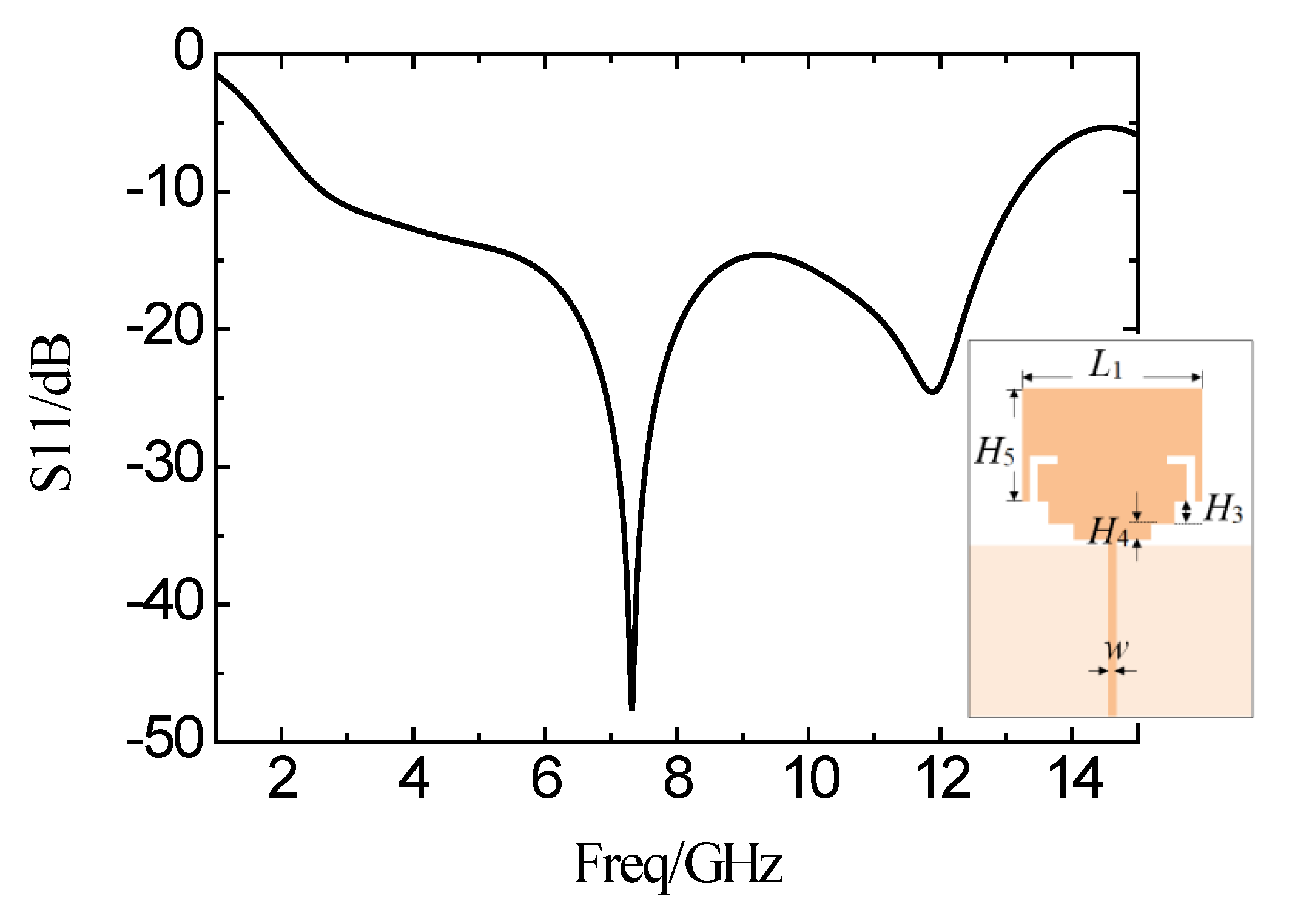
The structure shown in Figure 1 is designed and simulated by using Ansoft’s High-Frequency Structure Simulator (HFSS) software. First of all, the rectangular patch antenna is designed on a 36 mm × 23 mm Rogers 4350 substrate. The width of the feed line is 1.07 mm (w). Figure 3 is the simulated antenna surface current magnitude distribution. It can be seen that the intensity of the current amplitude along the edge of the slot is significantly enhanced. The reflection coefficient curve of the simulation is shown in Figure 4. The impedance bandwidth with the reflection coefficient of less than −10 dB is very narrow. The operating frequency band is from 2.03 GHz to 4.75 GHz. The bandwidth is only 2.62 GHz, and the minimum reflection coefficient is only −18 dB in the band.
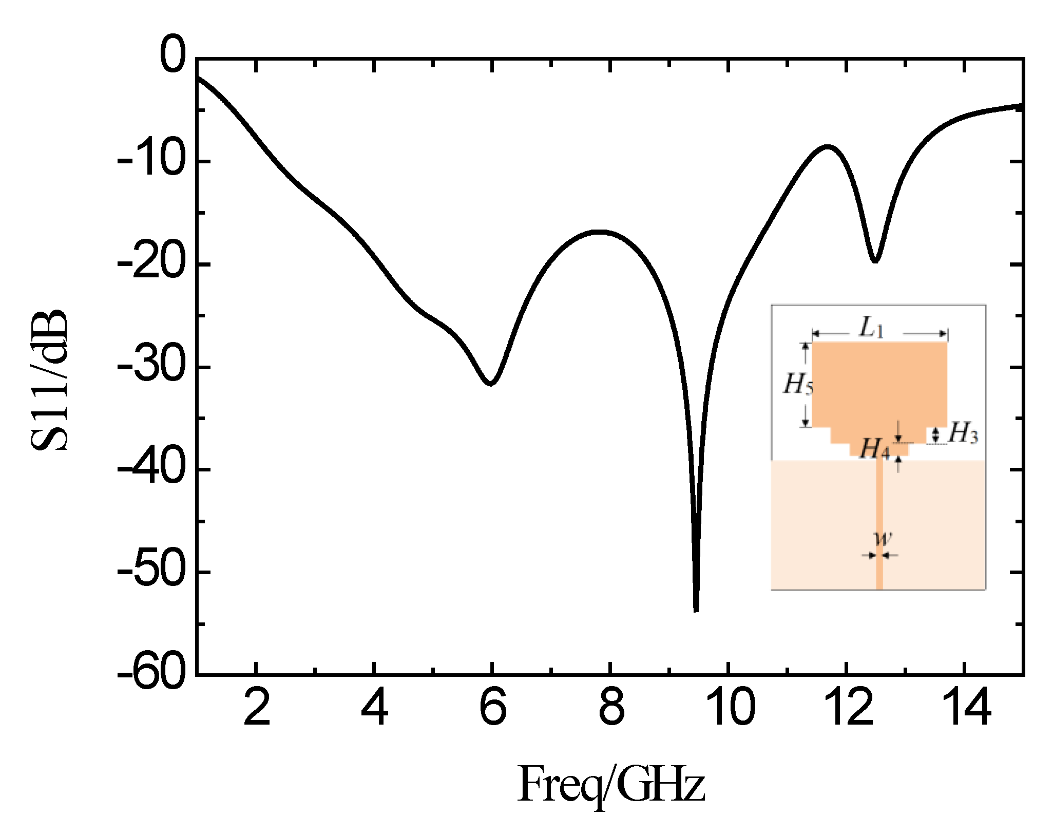
In order to expand the bandwidth and to make a good transition between the radiation patch and the feed line, the SIR microstrip structure is added between the radiating patch and the feed line. Figure 5 shows the simulation curve of the antenna reflection coefficient with SIR structure. The operating frequency band is from 2.4 GHz to 11.29 GHz, with a reflection coefficient of less than −10 dB. The bandwidth is 8.89 GHz. Two zero points appear in the passband. The bandwidth is increased, and the characteristics are improved in the band.
To further broaden the operating band and improve the characteristics in-band, two symmetric L-shaped slots are implemented on the side of the rectangular patch. The simulation curve of the reflection coefficient is shown in Figure 6. The frequency is from 2.78 GHz to 13.16 GHz, while the reflection coefficient is less than −10 dB. The bandwidth is broadened by 10.38 GHz so far.
Continuously, two symmetric I-shaped slots are implemented on the side of the SIR microstrip near the feed line. Figure 7 shows the simulation results of the reflection coefficient. It can be seen that the frequency band from 2.64 GHz to 13.93 GHz shows a small reflection coefficient of less than −10 dB. In this manner, the bandwidth is broadened by 11.29 GHz, with obvious improvements on the characteristics.
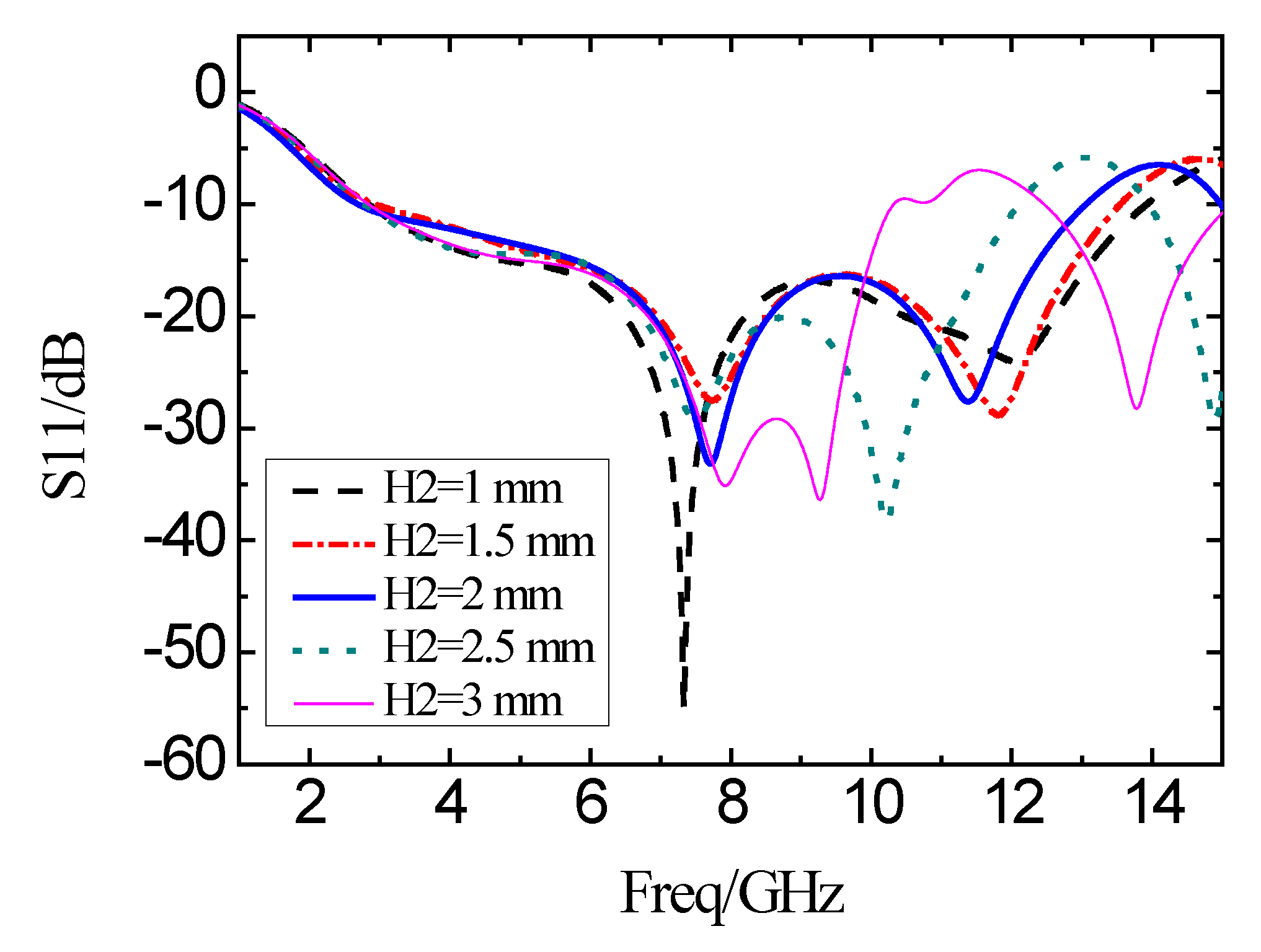
The effects of different structural parameters with L-shaped and I-shaped slots are simulated in terms of the reflection coefficient. The simulation results of the reflection coefficient with varied structures are shown in Figure 8, with the changing of the length H2. It can be seen that H2 is insensitive at low-frequency, while very sensitive at high-frequency. When H2 increases from 1 mm to 3 mm, the 10 dB impedance bandwidth decreases.
When the length L2 of the other side of the L-shaped slot is varied from 0.5 mm to 1.5 mm, the simulation results of the reflection coefficients are as shown in Figure 9. With a decrease in L2, the impedance bandwidth is broadened. But the in-band characteristics are degraded with an increase in L2. At the same time, the impedance bandwidth is narrowed, and the in-band characteristics are improved.
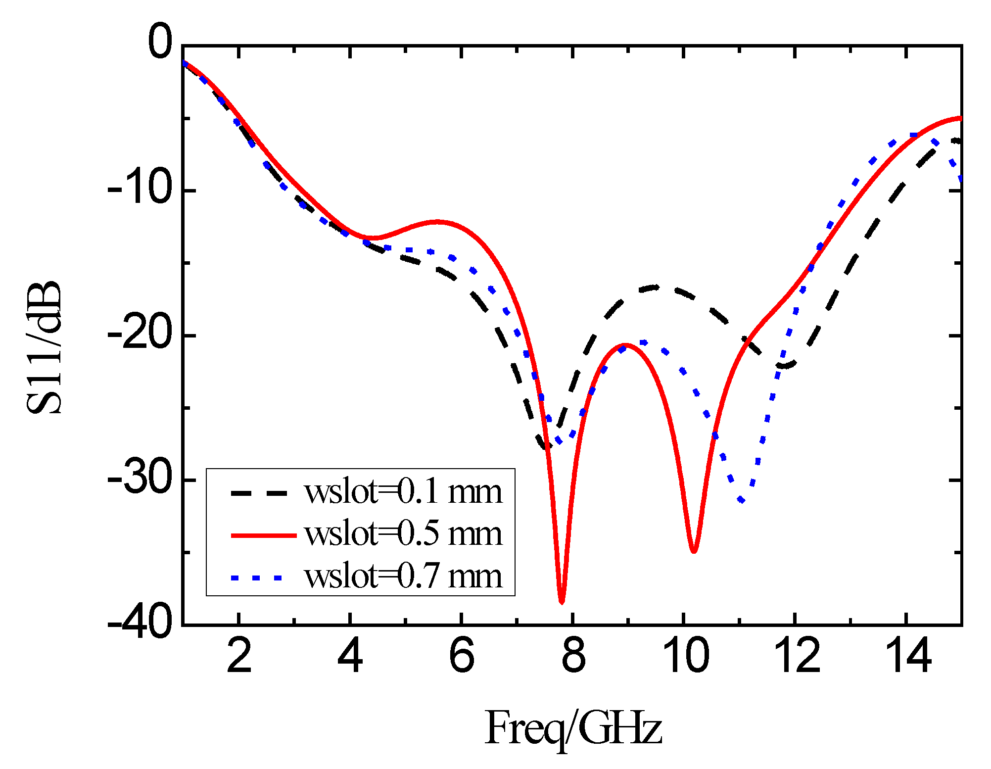
Figure 10 shows the simulation results of the reflection coefficient curve of the antenna when the widths wslot of the L-shaped slot are 0.1, 0.5, and 0.7 mm, respectively. As the width of the L-shaped slot is increased, the bandwidth is narrowed, and the in-band characteristics are improved. When the slot width is decreased, the bandwidth is increased accordingly. Meanwhile, the in-band characteristic is degraded.
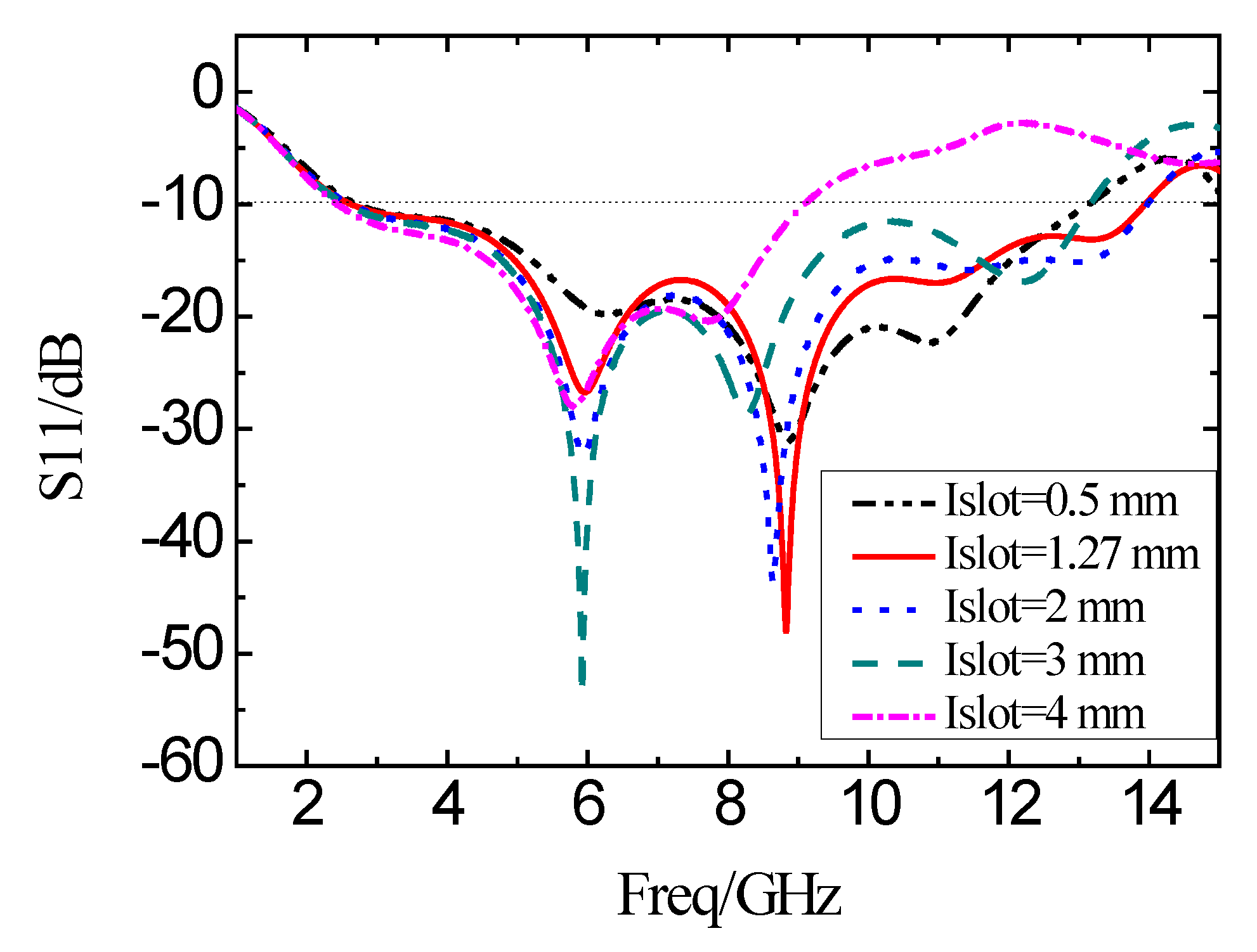
When the distance of the I-shaped slot from the center of the feed line is fixed to be 3.91 mm, the length of the I-shaped slot is varied. The corresponding simulation results of the reflection coefficient are shown in Figure 11. With the increase in the length (Islot), the bandwidth decreases. Meanwhile, the characteristics deteriorate in the operating band. In this manner, the length of the I-shaped slot should be smaller than the height (H4) of the SIR microstrip to avoid the obvious degradation of the bandwidth.
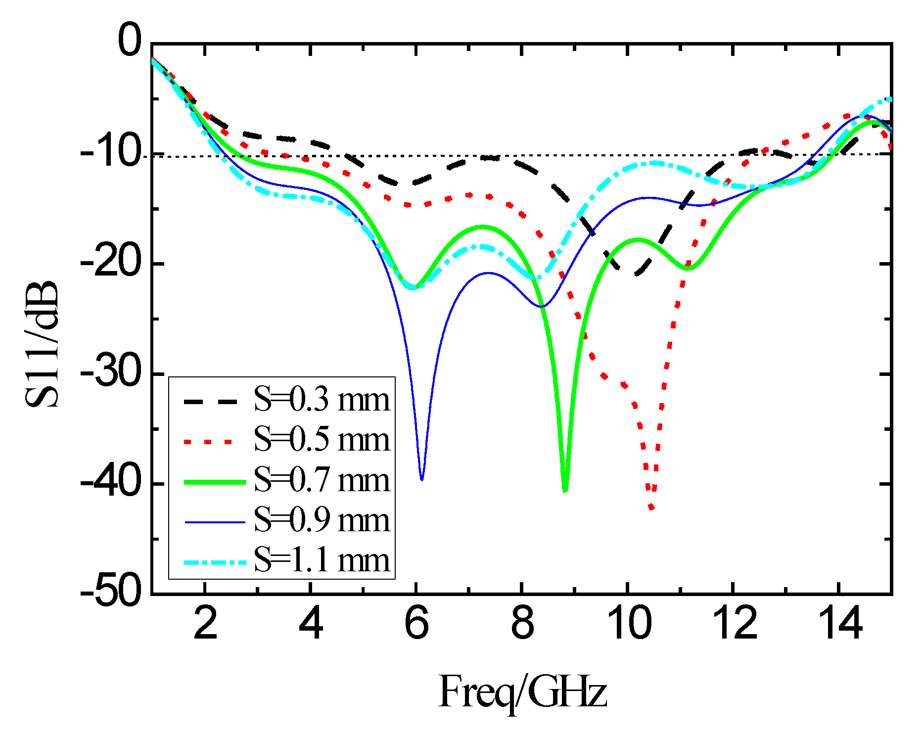
The structural parameter S in Figure 1 is the distance between the radiation patch on the top layer of the substrate and the ground plate on the back of the substrate, which is mainly for the good broadband matching performance. Figure 12 shows the reflection coefficient results when S changes from 0.3 mm to 1.1 mm in the step of 0.2 mm. When the value of S is less than 0.7 mm, the bandwidth decreases, and the in-band characteristic deteriorates sharply. When the value of S is greater than 0.7 mm, the bandwidth is slightly reduced, but the in-band characteristics may become unsatisfactory. Therefore, when the value of S is equal to 0.7 mm, the performance of the antenna is the best.
According to the above analysis, the key geometric values of the optimized antenna are shown in Table 1. The novel UWB antenna in the paper is designed with the following geometric parameters. The two L-shaped slots are implemented on both sides of the rectangular microstrip patch, respectively, with the length of the slot 4 mm and the width 0.5 mm. The L-shaped slot is 0.5 mm from the edge of the rectangular microstrip patch. The L-shaped slot can be used to extend the path of the surface current while miniaturizing the antenna size and improving the characteristics of the antenna in the ultra-wideband.

4. Results

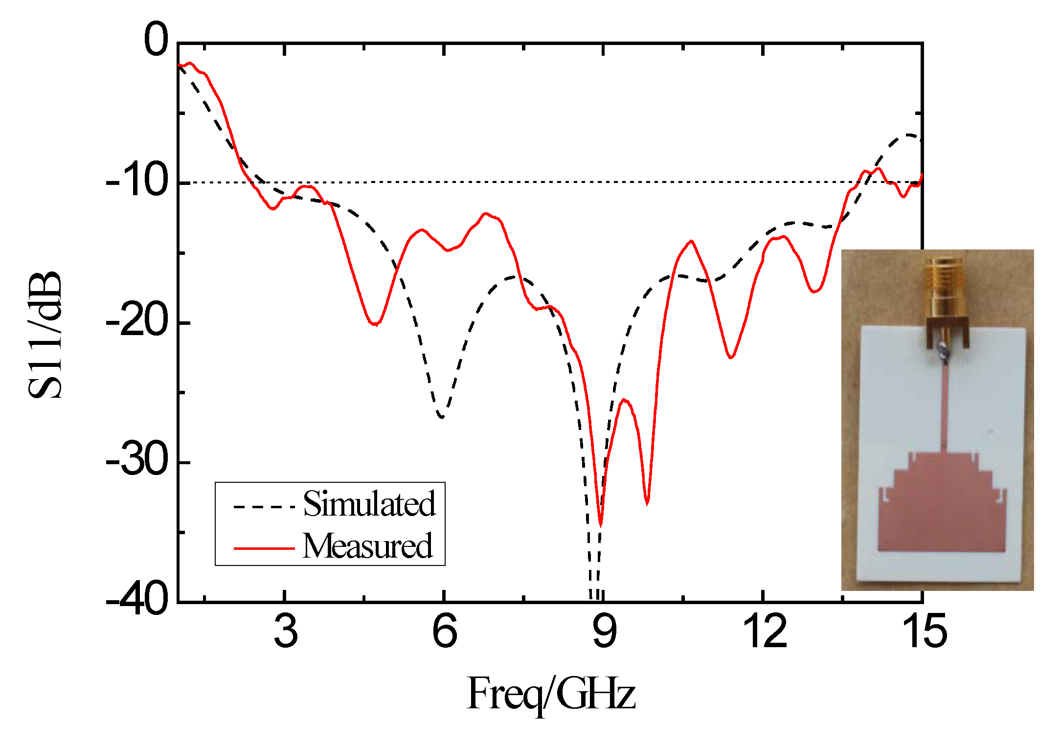
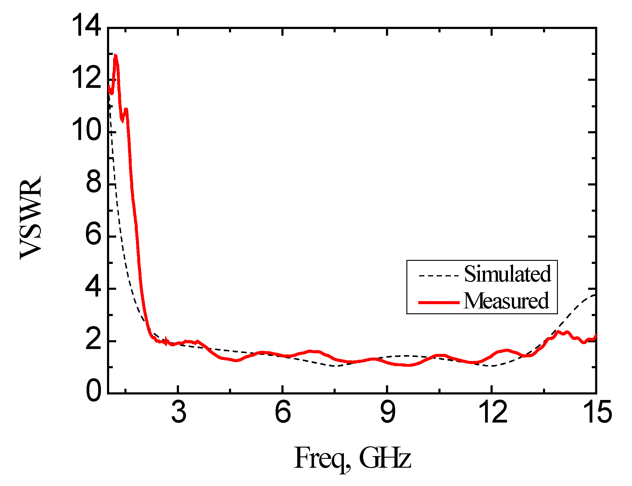
The antenna is fabricated and measured after optimizing the structure. Agilent’s vector network analyzer (VNA) (model: Agilent E8362B, Keysight, Santa Rosa, CA, USA) is used to measure in the anechoic chamber. Figure 13 shows the simulated and experimental measured results of the reflection coefficient based on the designed antenna. The frequency band with the reflection coefficient smaller than −10 dB is from 2.64 GHz to 13.93 GHz based on the simulation result. Based on the experimental measurement, the band with the reflection coefficient of less than −10 dB is from 2.39 GHz to 13.78 GHz with the bandwidth of 11.39 GHz. The frequency bandwidth for VSWR < 2 of the simulation is from 2.67 GHz to 13.52 GHz, and the measured frequency band is from 2.39 GHz to 13.57 GHz, as shown in Figure 14.
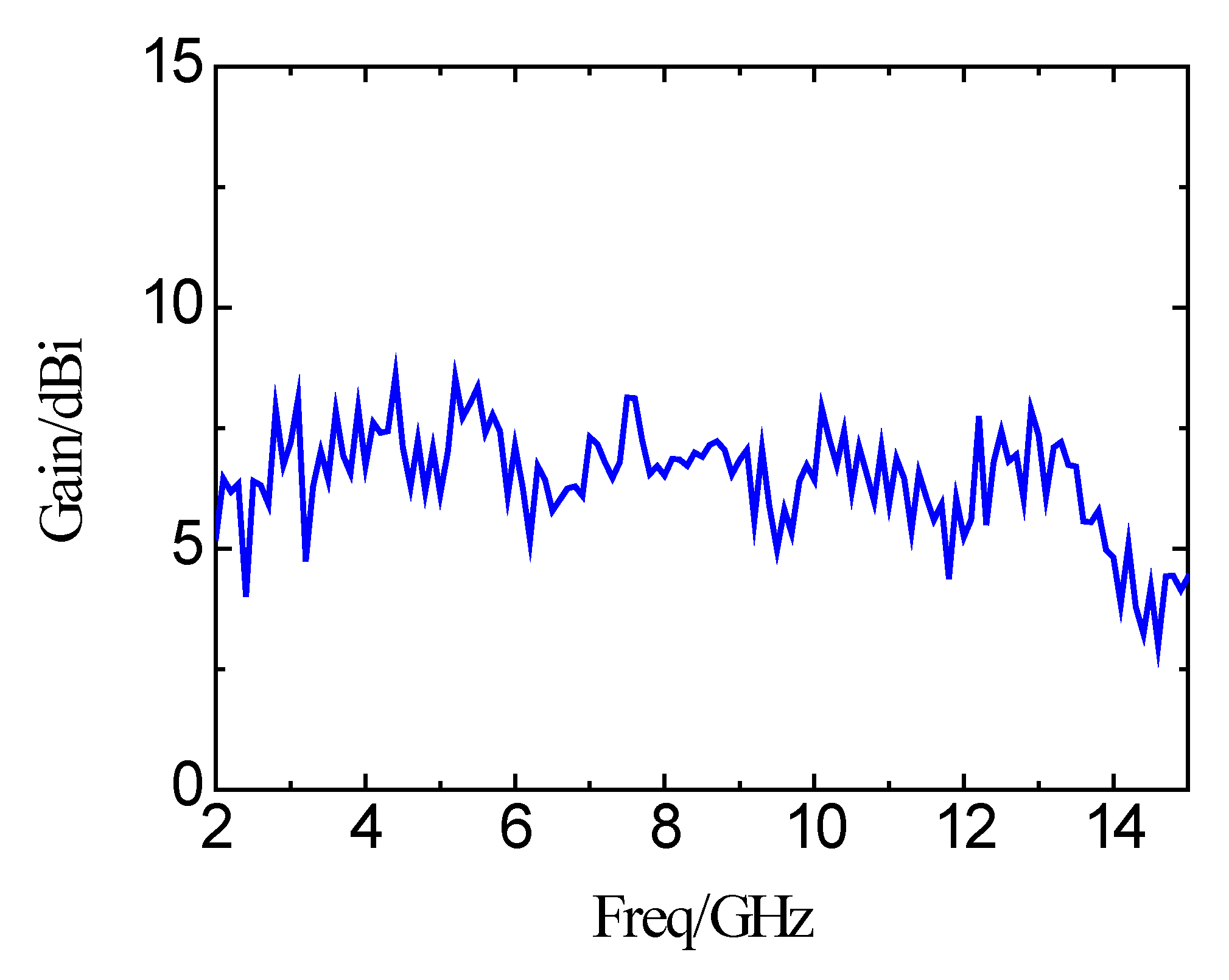
Figure 15 shows the xoz plane and yoz plane radiation patterns of far-field radiation at different frequencies of 4 GHz, 7 GHz, and 11 GHz. The simulations and measurements are shown at the same time. Based on the results, it can be seen that there is no obvious distortion of the radiation pattern on the xoz plane and yoz plane at the three frequency points. The xoz plane pattern is a directional radiation pattern, and the yoz plane pattern is close to the omnidirectional radiation pattern. Figure 16 is the measured peak gain of the proposed antenna. The peak gain of the antenna is varied in the range of 4 dBi to 8.54 dBi in the whole operating frequency band. For a clear comparison, the results of this paper are also included in Table 2. The key results of the published planar microstrip antennas are summarized in Table 2. It can be seen from Table 2 that there are obvious shortcomings for the published antennas. The UWB antenna proposed in the paper shows the best properties among the published results.

5. Conclusions

The ultra-wideband antenna with a stepped impedance microstrip connection between the radiating patch and the feed line is proposed and implemented in the paper. In the designed antenna, two L-shaped slot structures are loaded on both sides of the radiating patch. The measured impedance bandwidth reaches 11.39 GHz. The yoz plane radiation pattern of the antenna is close to the omnidirectional radiation mode. The peak gain of the UWB antenna is 4 dBi to 8.54 dBi in the range of 2.39 GHz to 13.78 GHz. This UWB antenna can be used in wireless sensor network nodes, radio wave energy harvesting, and portable wireless devices.

Author Contributions

These authors contributed equally to this work. Z.H.M. and Y.F.J. provided critical feedback, contributed to the research of this project. Z.H.M. and Y.F.J. conceived the study and the experiments. Z.H.M. and Y.F.J. carried out the experiments and data analysis. All authors discussed the results and participated in drafting and revising the manuscript. All authors have read and agreed to the published version of the manuscript.

Funding

The authors would like to acknowledge the financial support of this project by the National Natural Science Foundation of China (61774078) and the Fujian Natural Science Foundation Project (2019J01718) and the National Fund training project of Jimei University (ZP2020039).

Conflicts of Interest

The authors declare no conflict of interest.

References

  1. Sanz-lzquierdo, B.; Young, P.R.; Bai, Q.; Batchelor, J.C. Compact UWB Monopole for Multilayer Applications. Electron. Lett. 2006, 42, 5–9. [Google Scholar] [CrossRef]
  2. Bourdel, S.; Bachelet, Y.; Gaubert, J.; Vauche, R.; Fourquin, O.; Dehaese, N.; Barthelemy, H. A 9-pJ/Pulse 1.42-Vpp OOK CMOS UWB Pulse Generator for the 3.1–10.6-GHz FCC Band. IEEE Trans. Microwave Theory Technol. 2009, 58, 65–73. [Google Scholar] [CrossRef]
  3. Ruengwaree, A.; Ghose, A.; Kompa, G. A Novel UWB Rugby-Ball Antenna for Near-range Microwave Radar System. IEEE Trans. Microwave Theory Tech. 2006, 54, 2774–2779. [Google Scholar] [CrossRef]
  4. Tan, A.E.C.; Chia, M.Y.W. Measuring Human Body Impulse Response Using UWB Radar. Electron. Lett. 2005, 41, 1193–1194. [Google Scholar] [CrossRef]
  5. Xu, R.; Jin, Y.; Nguyen, C. Power-efficient switching-based CMOS UWB Transmitters for UWB Communications and Radar Systems. IEEE Trans. Microwave Theory Tech. 2006, 54, 3271–3277. [Google Scholar]
  6. Siriwongpairat, W.P.; Su, W.F.; Olfat, M.; Liu, K.R. Multiband-OFDM MIMO Coding Framework for UWB Communication Systems. IEEE Trans. Signal Process. 2006, 54, 214–224. [Google Scholar] [CrossRef]
  7. Ma, Z.H.; Jiang, Y.F. High-Density 3D Printable Chipless RFID Tag with Structure of Passive Slot Rings. Sensors 2019, 19, 2535. [Google Scholar] [CrossRef] [Green Version]
  8. Vito, G.D.; Stracca, G. Further comments on the design of log-periodic dipole Antennas. IEEE Trans. Antennas Propag. 1974, 22, 714–718. [Google Scholar] [CrossRef]
  9. Zhong, Y.W.; Yang, G.M.; Mo, J.Y.; Zheng, L. Compact circularly polarized archimedean spiral antenna for ultrawideband communication applications. IEEE Antennas Wirel. Propag. Lett. 2016, 16, 129–132. [Google Scholar] [CrossRef]
  10. Liang, J.; Chiau, C.C.; Chen, X.; Parini, C.G. Analysis and Design of UWB Disc Monopole Antennas. In Ultra Wideband Communications Technologies and System Design; IET: London, UK, 2004; pp. 103–106. [Google Scholar]
  11. Ammann, M.J.; Zhi, N.C. Wideband monopole antennas for multi-band wireless systems. IEEE Antennas Propag. Mag. 2003, 45, 146–150. [Google Scholar] [CrossRef]
  12. Chen, Z.N.; Chia, M.Y.W.; Ammann, M.J. Optimization and comparison of broadband monopoles. IEE Proc. Microw. Antennas Propag. 2003, 150, 429–435. [Google Scholar] [CrossRef] [Green Version]
  13. Liu, J.; Geng, J.; Wang, K.; Zhu, W. A low-profile, directional, ultrawideband antenna. IEEE Antennas Wirel. Propag. Lett. 2019, 18, 255–259. [Google Scholar] [CrossRef]
  14. Liang, J.; Chiau, C.C.; Chen, X.; Parini, C.G. Study of a printed circular disc monopole antenna for UWB systems. IEEE Trans. Antennas Propag. 2005, 53, 3500–3504. [Google Scholar] [CrossRef]
  15. Wu, Q.; Jin, R.H.; Geng, J.P.; Ding, M. Compact CPW-fed quasi-circular monopole with very wide bandwidth. Electron. Lett. 2007, 43, 69–70. [Google Scholar] [CrossRef]
  16. Yassin, M.E.; Mohamed, H.A.; Abdallah, E.A.F.; EI-Hennawy, H.S. Circularly polarized wideband-to-narrowband switchable Antenna. IEEE Access 2019, 7, 36010–36018. [Google Scholar] [CrossRef]
  17. Nazli, H.; Bicak, E.; Turetken, B.; Sezgin, M. An improved design of planar elliptical dipole Antenna for UWB applications. IEEE Antennas Wirel. Propag. Lett. 2010, 9, 264–267. [Google Scholar] [CrossRef]
  18. Low, Z.N.; Cheong, J.H.; Law, C.L. Low-cost PCB Antenna for UWB applications. IEEE Antennas Wirel. Propag. Lett. 2005, 4, 237–239. [Google Scholar] [CrossRef]
  19. Gopikrishna, M.; Krishna, D.D.; Aanandan, C.K.; Mohanan, P.; Vasudevan, K. Compact linear tapered slot Antenna for UWB applications. Electron. Lett. 2008, 44, 1174–1175. [Google Scholar] [CrossRef]
  20. Yang, Y.; Zhao, Z.; Ding, X.; Nie, Z.; Liu, Q.H. Compact UWB slot Antenna utilizing traveling-wave mode based on slotline transitions. IEEE Trans. Antennas Propag. 2019, 67, 140–150. [Google Scholar] [CrossRef]
  21. Hussain, R.; Sharawi, M.S.; Shamim, A. An integrated four-element slot-based MIMO and a UWB sensing Antenna system for CR platforms. IEEE Trans. Antennas Propag. 2018, 66, 978–983. [Google Scholar] [CrossRef] [Green Version]
  22. Shirazi, M.; Li, T.; Huang, J.; Gong, X. A reconfigurable dual-polarization slot-ring Antenna element with wide bandwidth for array applications. IEEE Trans. Antennas Propag. 2018, 66, 5943–5954. [Google Scholar] [CrossRef]
  23. Qu, S.W.; Li, J.L.; Xue, Q. Broadband microstrip-line-fed wide slot Antenna with improved patterns. Electron. Lett. 2006, 42, 893–894. [Google Scholar] [CrossRef]
  24. Paul, P.M.; Kandasamy, K.; Sharawi, M.S.; Majumder, B. Dispersion-engineered transmission line loaded slot Antenna for UWB applications. IEEE Antennas Wirel. Propag. Lett. 2019, 18, 323–327. [Google Scholar] [CrossRef]
  25. Pourahmadazar, J.; Ghobadi, C.; Nourinia, J.; Felegari, N.; Shirzad, H. Broadband CPW-fed circularly polarized square slot Antenna with inverted-L strips for UWB applications. IEEE Antennas Wirel. Propag. Lett. 2011, 10, 369–372. [Google Scholar] [CrossRef]
  26. Sadat, S.; Fardis, M.; Geran, F.; Dadashzadeh, G.; Hojjat, N.; Roshandel, M. A compact microstrip square-ring slot Antenna for UWB applications. In Proceedings of the 2006 IEEE Antennas and Propagation Society International Symposium, Albuquerque, NM, USA, 9–14 July 2006; pp. 4629–4632. [Google Scholar]
  27. Lee, C.H.; Hsu, C.I.; Jhuang, H.K. Design of a New Tri-Band Microstrip BPF Using Combined Quarter-Wavelength SIRs. IEEE Microw. Wirel. Compon. Lett. 2006, 16, 594–596. [Google Scholar] [CrossRef]
  28. Hsu, C.; Kuo, J. Design of cross-coupled quarter-wave SIR filters with plural transmission zeros. In Proceedings of the 2006 IEEE MTT-S International Microwave Symposium Digest, San Francisco, CA, USA, 11–16 June 2006; pp. 1205–1208. [Google Scholar]
  29. Lerdwanittip, R.; Namsang, A.; Akkaraekthalin, P. Bandpass filters using T-shape stepped impedance resonators for wide harmonics suppression and their application for a diplexer. J. Semicond. Technol. Sci. 2011, 11, 65–72. [Google Scholar] [CrossRef]
  30. Zarghooni, B.; Denidni, T.A. New compact metamaterial unit-cell using SIR technique. IEEE Microw. Wirel. Compon. Lett. 2014, 24, 315–317. [Google Scholar] [CrossRef]
  31. Makimoto, M.; Yamashita, S. Bandpass filters using parallel coupled stripline stepped impedance resonators. IEEE Trans. Microw. Theory Tech. 1980, 28, 1413–1417. [Google Scholar] [CrossRef]
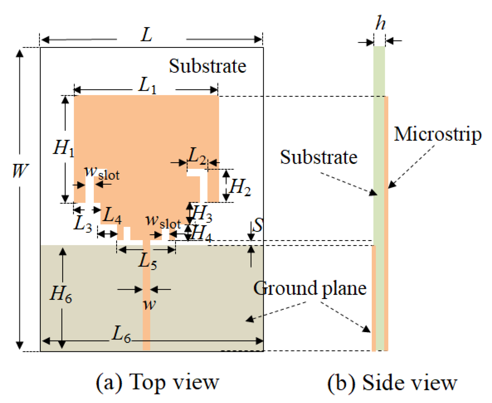
Figure 1. Structure of the proposed ultra-wideband (UWB) antenna. (a) Top view; (b) Side view.
Micromachines 11 00828 g001
Figure 2. Structure of the stepped impedance resonator (SIR).
Micromachines 11 00828 g002
Figure 3. The current distribution of the antenna.
Micromachines 11 00828 g003
Figure 4. Simulation results of the reflection coefficient of the rectangular microstrip patch antenna.
Micromachines 11 00828 g004
Figure 5. Simulation results of the reflection coefficient curve of the antenna after adding SIR structure.
Micromachines 11 00828 g005
Figure 6. Simulation results of the reflection coefficient curve after loading two L-shaped slots on the microstrip patch.
Micromachines 11 00828 g006
Figure 7. Simulation results of the reflection coefficient curve after loading the I-shaped slot on the SIR.
Micromachines 11 00828 g007
Figure 8. Simulation results of the reflection coefficient with different H2.
Micromachines 11 00828 g008
Figure 9. Simulation results of the reflection coefficient with different L2.
Micromachines 11 00828 g009
Figure 10. Simulation results of the reflection coefficient with different wslot.
Micromachines 11 00828 g010
Figure 11. Simulation results of the reflection coefficient of antennas with the varying I-shaped slot length.
Micromachines 11 00828 g011
Figure 12. Simulation results of the reflection coefficient of the S changes.
Micromachines 11 00828 g012
Figure 13. Simulation and experimental measurement of the reflection coefficient of the proposed antenna.
Micromachines 11 00828 g013
Figure 14. Simulation and experimental measurement of voltage standing wave ratio (VSWR) of the proposed antenna.
Micromachines 11 00828 g014
Figure 15. Simulation and measurement radiated pattern on xoz plane and yoz plane, respectively. (a) 4 GHz, (b) 7 GHz, (c) 11 GHz.
Micromachines 11 00828 g015
Figure 16. Measured peak gains of the antenna.
Micromachines 11 00828 g016
Table 1. Parameter values of the ultra-wideband (UWB) antenna.
ParameterValue (mm)ParameterValue (mm)
L118H111
L21H22
L31.465H32.5
L44H42.5
L511.07wslot0.5
L623H616.8
w1.07h0.508
Islot1.27S0.7
W36L23
Islot is the length of the I-shaped slot.
Table 2. Comparison of the published UWB antennas.
ReferencesTypeDielectric ConstantSize (mm2)Bandwidth (GHz)Peak Gain (dBi)Gain Variation (dB)
[14]Disc monopole4.742 × 502.78–9.78--
[15]Quasi-circular2.6540 × 302.55–18.5--
[16]Microstrip3.3845 × 503–11.574.2–6.912.71
[17]Dipole2.2106 × 851.1–11±510
[18]Reconfigurable Slot-ring array2.280 × 801.8–3.7 and 4.5–8.232.4–3.10.7
[19]Annular slot3.48120 × 600.75–7.650.5–3.22.7
[20]Slot4.425 × 302.9–11.82–64
[21]Slot4.430 × 304–100–4.84.8
[22]Tapered slot4.430 × 13.52.95–141.7–4.12.4
[23]Slot2.3352 × 622.1–11.53.5–73.5
[24]Square slot2.250 × 502.1–11.53.8–5.71.9
[25]Square slot4.460 × 602.8–133–4.131.13
[26]Square-ring slot3.4120 × 1003–112–62
This paperSlot3.6636 × 232.39–13.784–8.544.54