
Microvalve with Trapezoid-Shaped Cross-Section for Deep Microchannels


Abstract
:1. Introduction
2. Material and Method
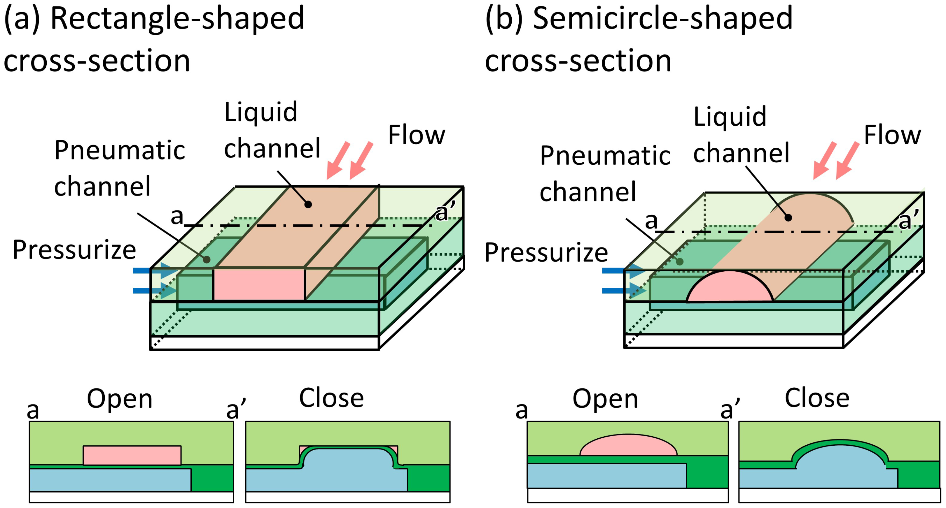
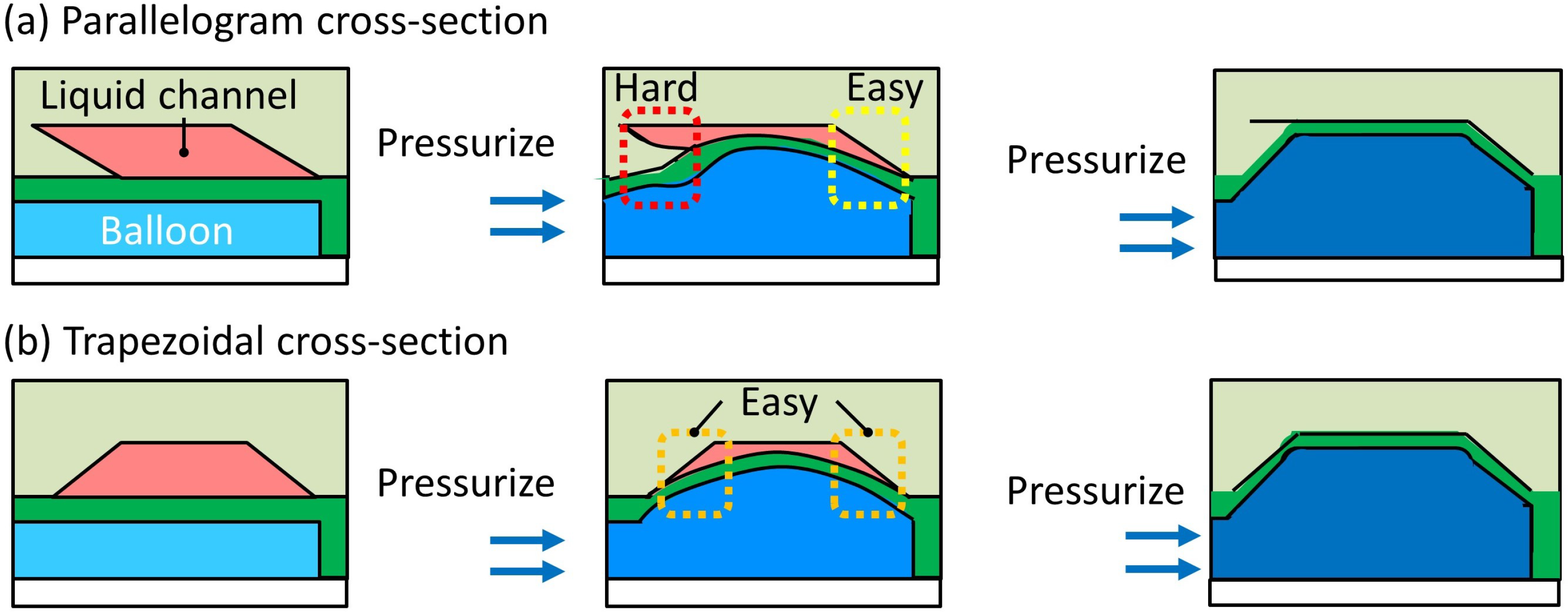
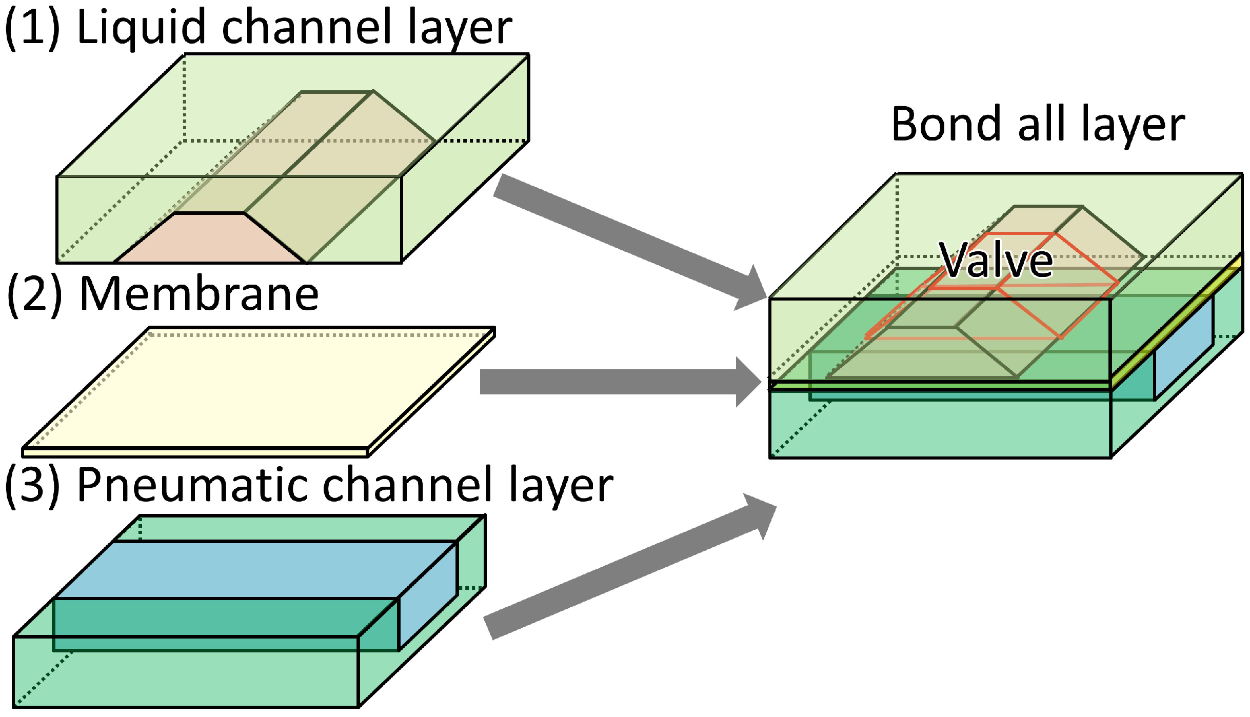
2.1. Working Principle of the Trapezoid-Shaped Cross-Section Microvalve
2.2. Fabrication
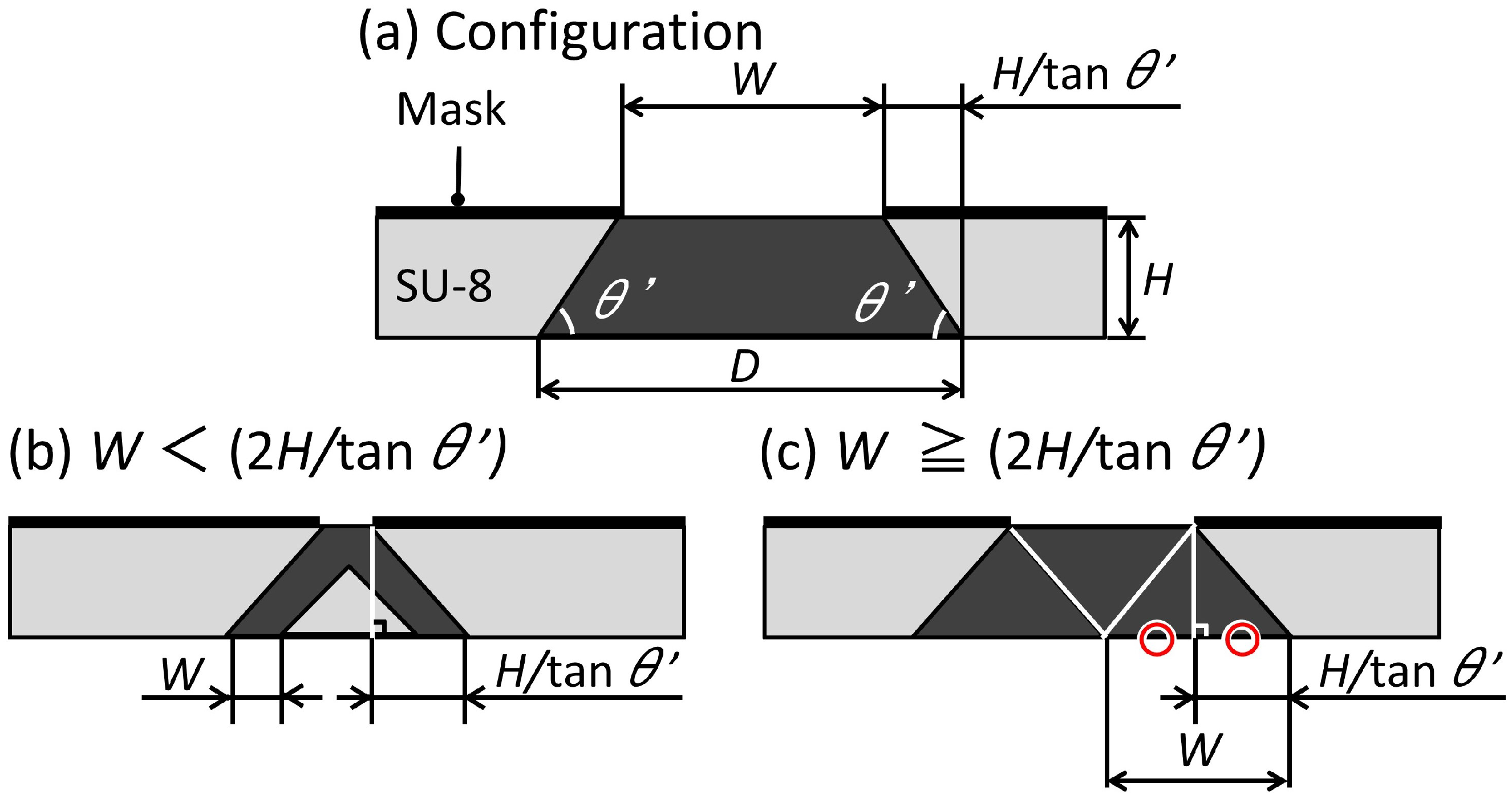
2.2.1. Design
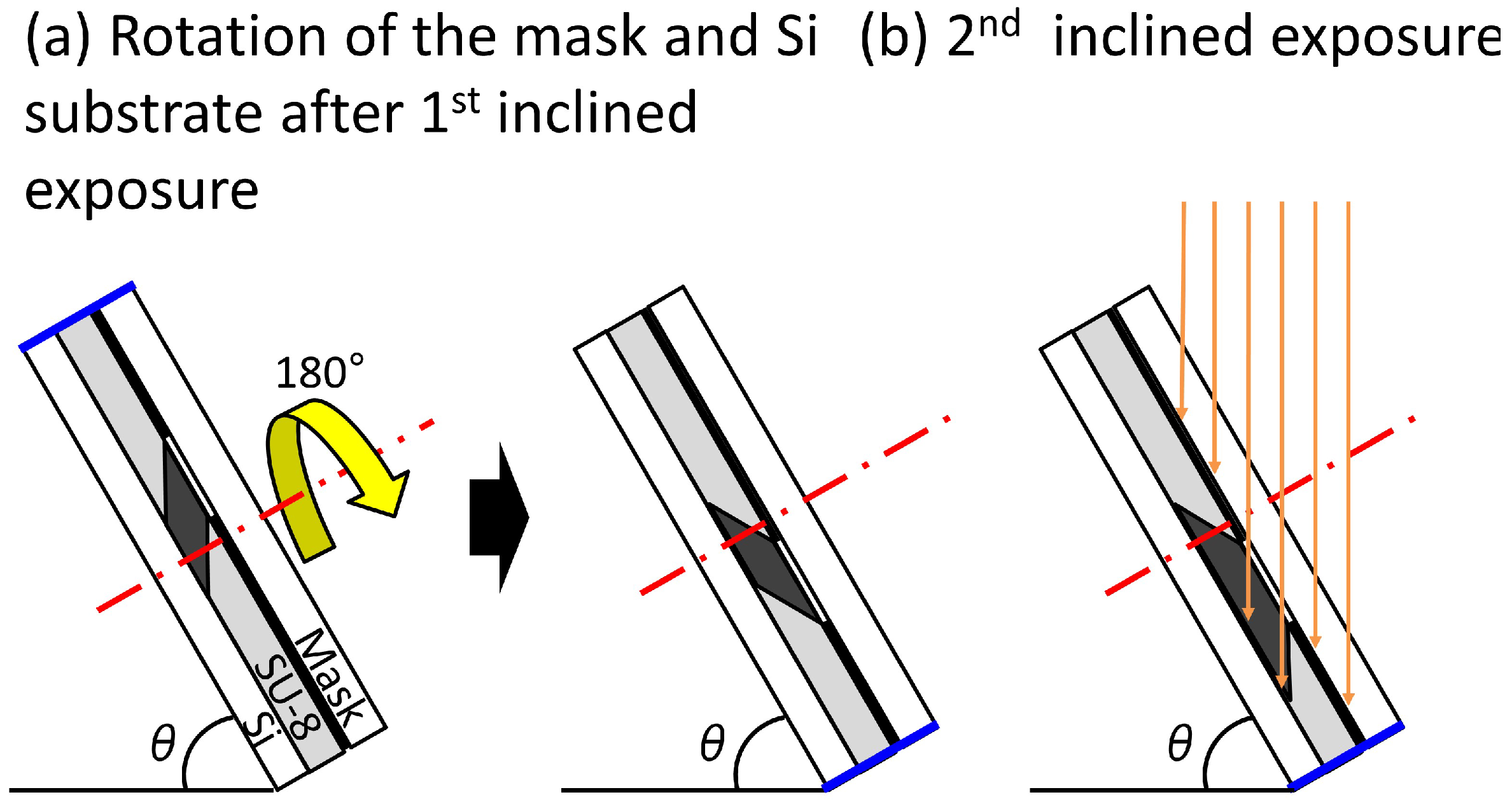
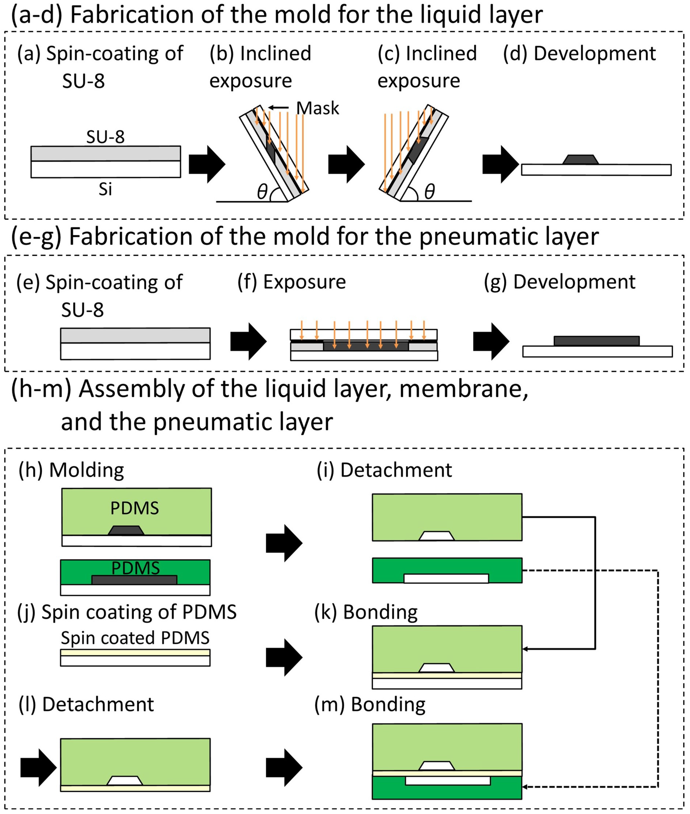
2.2.2. Fabrication Method of the Trapezoid-Shaped Cross Sectional Microvalve
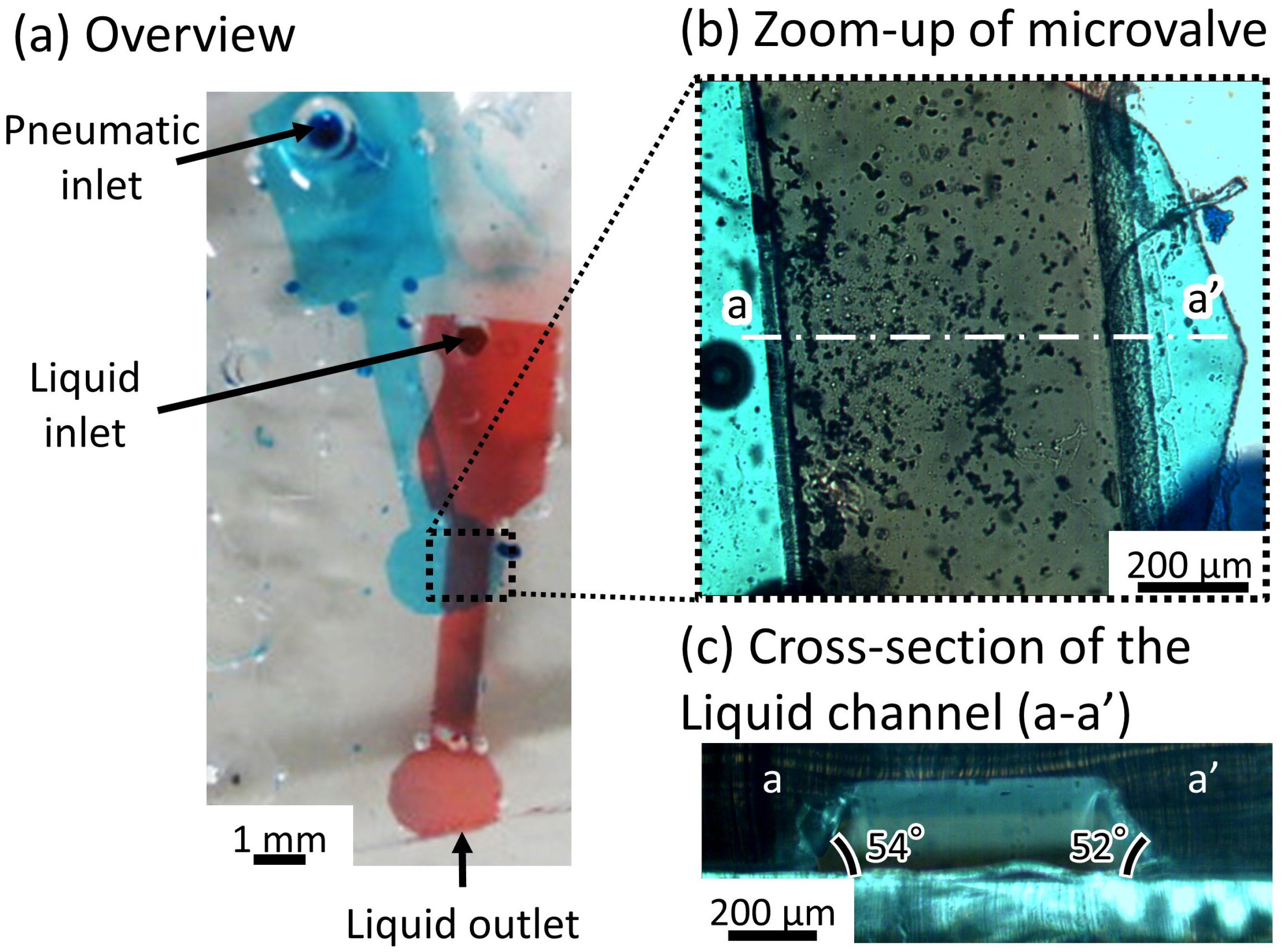
2.2.3. Fabricated Microvalve
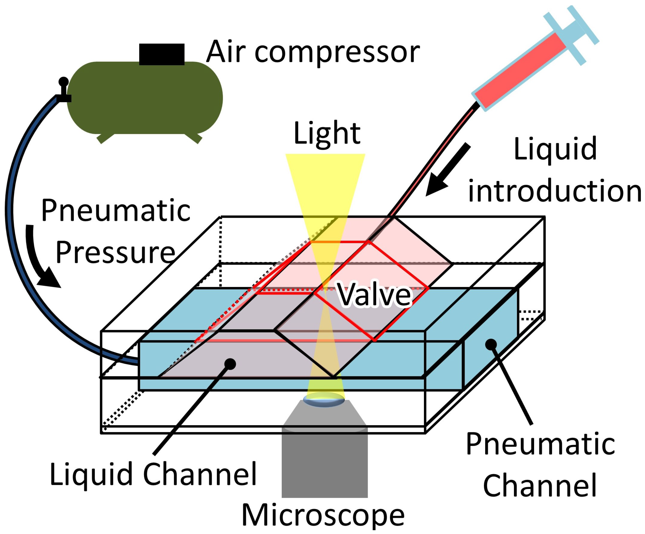
2.3. Experimental Methods
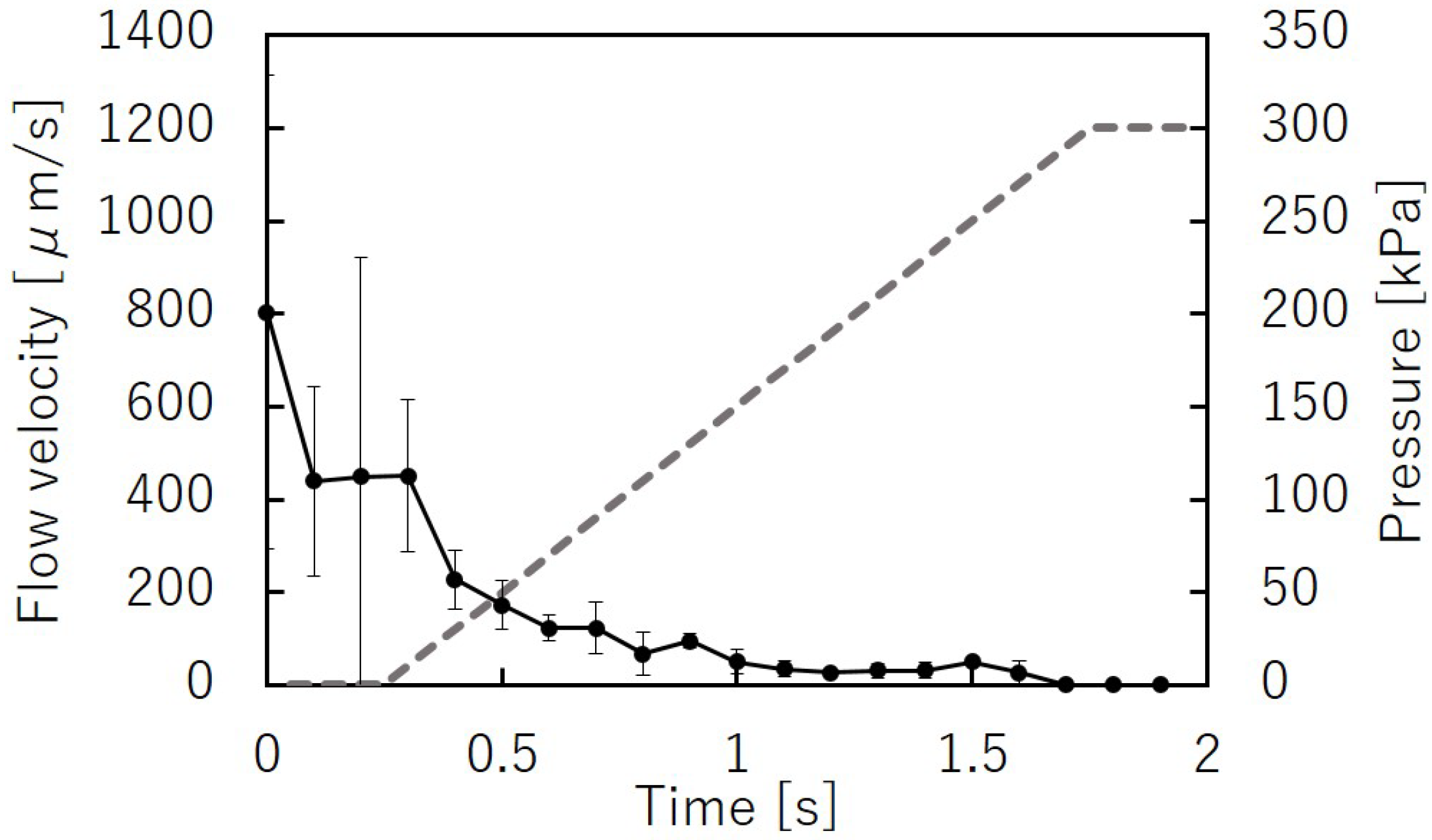
2.3.1. Flow Velocity and Pressure
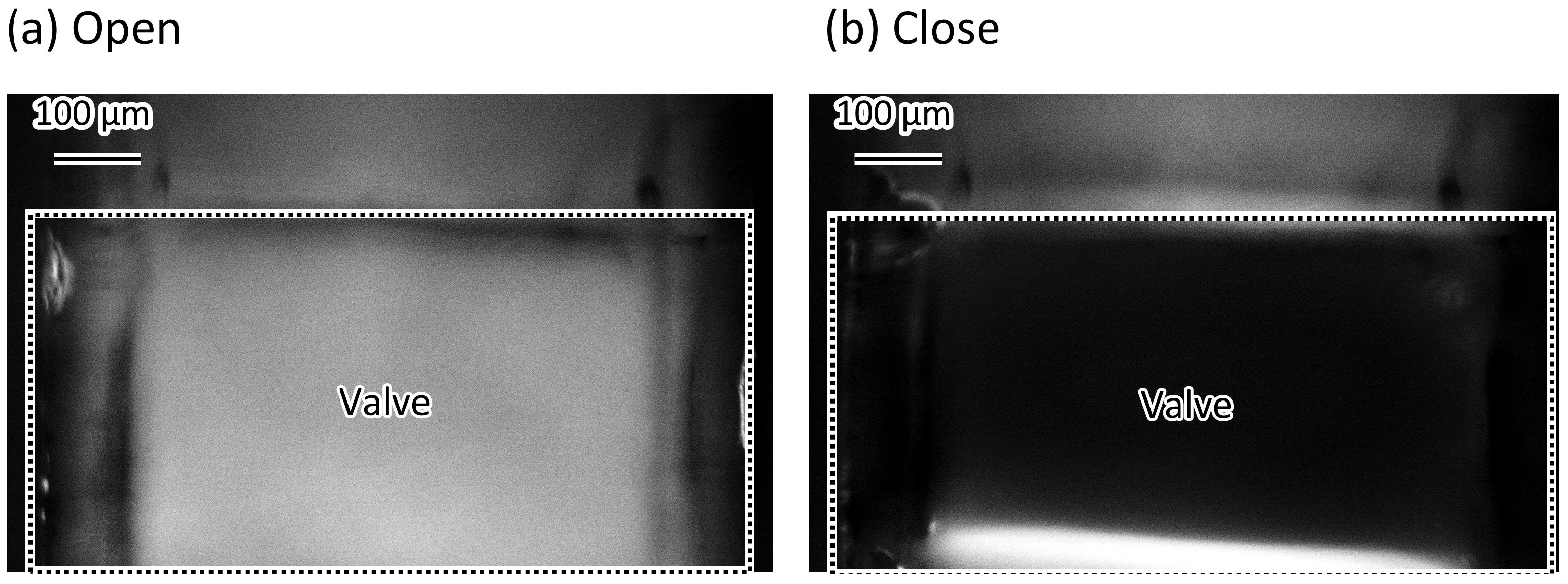
2.3.2. Complete Sealing of the Microvalve
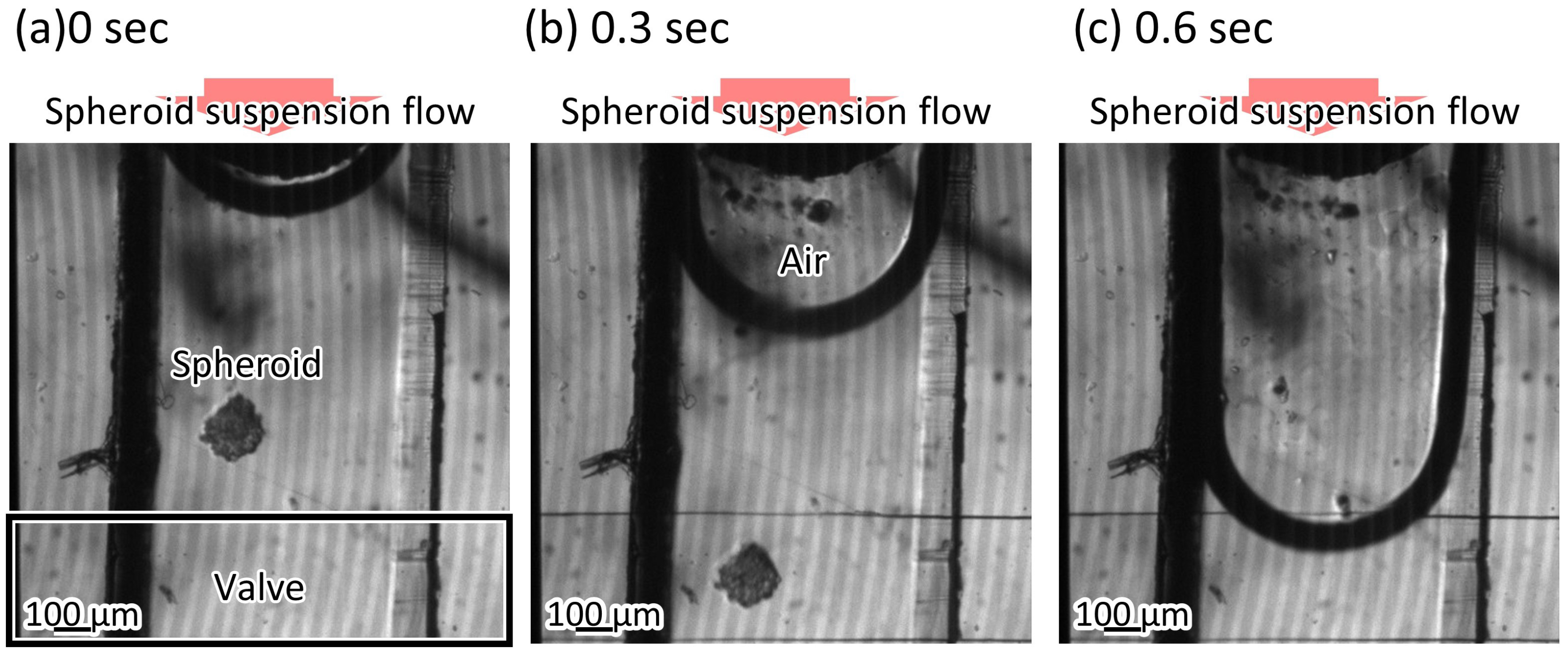
2.3.3. Response Time of the Microvalve
3. Results
3.1. Flow Velocity and Pressure
3.2. Complete Sealing of the Microvalve
3.3. Response Time of the Microvalve
4. Discussion
5. Conclusions
Supplementary Materials
Author Contributions
Funding
Institutional Review Board Statement
Data Availability Statement
Acknowledgments
Conflicts of Interest
References
- Velve-Casquillas, G.; Le Berre, M.; Piel, M.; Tran, P.T. Microfluidic tools for cell biological research. Nano Today 2010, 5, 28–47. [Google Scholar] [CrossRef] [Green Version]
- Kricka, L.J.; Wilding, P. Microchip PCR. Anal. Bioanal. Chem. 2003, 377, 820–825. [Google Scholar] [CrossRef]
- Woolley, A.T.; Hadley, D.; Landre, P.; DeMello, A.J.; Mathies, R.A.; Northrup, M.A. Functional integration of PCR amplification and capillary electrophoresis in a microfabricated DNA analysis device. Anal. Chem. 1996, 68, 4081–4086. [Google Scholar] [CrossRef]
- Goedecke, N.; McKenna, B.; El-Difrawy, S.; Carey, L.; Matsudaira, P.; Ehrlich, D. A high-performance multilane microdevice system designed for the DNA forensics laboratory. Electrophoresis 2004, 25, 1678–1686. [Google Scholar] [CrossRef]
- Hadd, A.G.; Raymond, D.E.; Halliwell, J.W.; Jacobson, S.C.; Ramsey, J.M. Microchip Device for Performing Enzyme Assays. Anal. Chem. 1997, 69, 3407–3412. [Google Scholar] [CrossRef] [PubMed]
- Herr, A.E.; Molho, J.I.; Drouvalakis, K.A.; Mikkelsen, J.C.; Utz, P.J.; Santiago, J.G.; Kenny, T.W. On-chip coupling of isoelectric focusing and free solution electrophoresis for multidimensional separations. Anal. Chem. 2003, 75, 1180–1187. [Google Scholar] [CrossRef] [PubMed]
- Chiem, N.; Harrison, D.J. Microchip-based capillary electrophoresis for immunoassays: Analysis of monoclonal antibodies and theophylline. Anal. Chem. 1997, 69, 373–378. [Google Scholar] [CrossRef] [PubMed]
- Wang, Z.; Kim, M.C.; Marquez, M.; Thorsen, T. High-density microfluidic arrays for cell cytotoxicity analysis. Lab Chip 2007, 7, 740–745. [Google Scholar] [CrossRef] [PubMed]
- Pasirayi, G.; Scott, S.M.; Islam, M.; O’Hare, L.; Bateson, S.; Ali, Z. Low cost microfluidic cell culture array using normally closed valves for cytotoxicity assay. Talanta 2014, 129, 491–498. [Google Scholar] [CrossRef] [PubMed] [Green Version]
- Frank, T.; Tay, S. Automated co-culture system for spatiotemporal analysis of cell-to-cell communication. Lab Chip 2015, 15, 2192–2200. [Google Scholar] [CrossRef]
- Majumdar, D.; Gao, Y.; Li, D.; Webb, D.J. Co-culture of neurons and glia in a novel microfluidic platform. J. Neurosci. Methods 2011, 196, 38–44. [Google Scholar] [CrossRef] [PubMed] [Green Version]
- Kaminaga, M.; Ishida, T.; Kadonosono, T.; Kizaka-Kondoh, S.; Omata, T. Microfluidic Device for Screening for Target Cell-Specific Binding Molecules by Using Adherent Cells. Micromachines 2019, 10, 41. [Google Scholar] [CrossRef] [Green Version]
- Albanese, A.; Lam, A.K.; Sykes, E.A.; Rocheleau, J.V.; Chan, W.C. Tumour-on-a-chip provides an optical window into nanoparticle tissue transport. Nat. Commun. 2013, 4, 1–8. [Google Scholar] [CrossRef] [PubMed] [Green Version]
- Lim, W.; Park, S. A microfluidic spheroid culture device with a concentration gradient generator for high-throughput screening of drug efficacy. Molecules 2018, 23, 3355. [Google Scholar] [CrossRef] [PubMed] [Green Version]
- Pereira, P.M.; Berisha, N.; Bhupathiraju, N.D.K.; Fernandes, R.; Tomé, J.P.; Drain, C.M. Cancer cell spheroids are a better screen for the photodynamic efficiency of glycosylated photosensitizers. PLoS ONE 2017, 12, e0177737. [Google Scholar] [CrossRef]
- Koch, S.; Schwinger, C.; Kressler, J.; Heinzen, C.; Rainov, N.G. Alginate encapsulation of genetically engineered mammalian cells: Comparison of production devices, methods and microcapsule characteristics. J. Microencapsul. 2003, 20, 303–316. [Google Scholar] [CrossRef]
- Sakai, S.; Kawabata, K.; Ono, T.; Ijima, H.; Kawakami, K. Development of mammalian cell-enclosing subsieve-size agarose capsules (<100 micrometres) for cell therapy. Biomaterials 2005, 26, 4786–4792. [Google Scholar] [CrossRef]
- Makoto, O.; Tsutomu, I. Methods in Marine Zooplankton Ecology; Wiley: Hoboken, NJ, USA, 1984. [Google Scholar]
- Melin, J.; Quake, S.R. Microfluidic large-scale integration: The evolution of design rules for biological automation. Annu. Rev. Biophys. Biomol. Struct. 2007, 36, 213–231. [Google Scholar] [CrossRef] [PubMed] [Green Version]
- Oh, K.W.; Ahn, C.H. A review of microvalves. J. Micromechanics Microengineering 2006, 16, R13. [Google Scholar] [CrossRef]
- Shin, J.; Park, H.; Dang, V.B.; Kim, C.W.; Kim, S.J. Elastomeric microfluidic valve with low, constant opening threshold pressure. RSC Adv. 2015, 5, 23239–23245. [Google Scholar] [CrossRef]
- Unger, M.A.; Chou, H.P.; Thorsen, T.; Scherer, A.; Quake, S.R. Monolithic microfabricated valves and pumps by multilayer soft lithography. Science 2000, 288, 113–116. [Google Scholar] [CrossRef] [Green Version]
- Al Habyan, S.; Kalos, C.; Szymborski, J.; McCaffrey, L. Multicellular detachment generates metastatic spheroids during intra-abdominal dissemination in epithelial ovarian cancer. Oncogene 2018, 37, 5127–5135. [Google Scholar] [CrossRef]
- Lau, A.; Yip, H.; Ng, K.; Cui, X.; Lam, R. Dynamics of Microvalve Operations in Integrated Microfluidics. Micromachines 2014, 5, 50–65. [Google Scholar] [CrossRef] [Green Version]
- Fordyce, P.M.; Diaz-Botia, C.A.; Derisi, J.L.; Gomez-Sjoberg, R. Systematic characterization of feature dimensions and closing pressures for microfluidic valves produced via photoresist reflow. Lab Chip 2012, 12, 4287–4295. [Google Scholar] [CrossRef]
- Kaminaga, M.; Ishida, T.; Omata, T. Fabrication of Pneumatic Microvalve for Tall Microchannel Using Inclined Lithography. Micromachines 2016, 7, 224. [Google Scholar] [CrossRef] [Green Version]
- Hansson, J.; Hillmering, M.; Haraldsson, T.; Van Der Wijngaart, W. Leak-tight vertical membrane microvalves. Lab Chip 2016, 16, 1439–1446. [Google Scholar] [CrossRef]
- Rammohan, A.; Dwivedi, P.K.; Martinez-Duarte, R.; Katepalli, H.; Madou, M.J.; Sharma, A. One-step maskless grayscale lithography for the fabrication of 3-dimensional structures in SU-8. Sens. Actuators B Chem. 2011, 153, 125–134. [Google Scholar] [CrossRef]
- Han, M.; Lee, W.; Lee, S.K.; Lee, S.S. Fabrication of 3D microstructures with inclined/rotated UV lithography. In Proceedings of the The Sixteenth Annual International Conference on Micro Electro Mechanical Systems, Kyoto, Japan, 19–23 January 2003; pp. 554–557. [Google Scholar] [CrossRef]
- Ishida, T.; Shimamoto, T.; Kaminaga, M.; Kuchimaru, T.; Kizaka-Kondoh, S.; Omata, T. Microfluidic High-Migratory Cell Collector Suppressing Artifacts Caused by Microstructures. Micromachines 2019, 10, 116. [Google Scholar] [CrossRef] [Green Version]


Publisher’s Note: MDPI stays neutral with regard to jurisdictional claims in published maps and institutional affiliations. |
© 2021 by the authors. Licensee MDPI, Basel, Switzerland. This article is an open access article distributed under the terms and conditions of the Creative Commons Attribution (CC BY) license (https://creativecommons.org/licenses/by/4.0/).
Share and Cite
Kaminaga, M.; Ishida, T.; Omata, T. Microvalve with Trapezoid-Shaped Cross-Section for Deep Microchannels. Micromachines 2021, 12, 1403. https://doi.org/10.3390/mi12111403
Kaminaga M, Ishida T, Omata T. Microvalve with Trapezoid-Shaped Cross-Section for Deep Microchannels. Micromachines. 2021; 12(11):1403. https://doi.org/10.3390/mi12111403
Chicago/Turabian StyleKaminaga, Maho, Tadashi Ishida, and Toru Omata. 2021. "Microvalve with Trapezoid-Shaped Cross-Section for Deep Microchannels" Micromachines 12, no. 11: 1403. https://doi.org/10.3390/mi12111403
APA StyleKaminaga, M., Ishida, T., & Omata, T. (2021). Microvalve with Trapezoid-Shaped Cross-Section for Deep Microchannels. Micromachines, 12(11), 1403. https://doi.org/10.3390/mi12111403