
A DIY Fabrication Approach for Ultra-Thin Focus-Tunable Liquid Lens Using Electrohydrodynamic Pump

 ,
,  , and
, and 
Abstract
:1. Introduction
2. EHD Pump to Focus-Tunable Liquid Lens
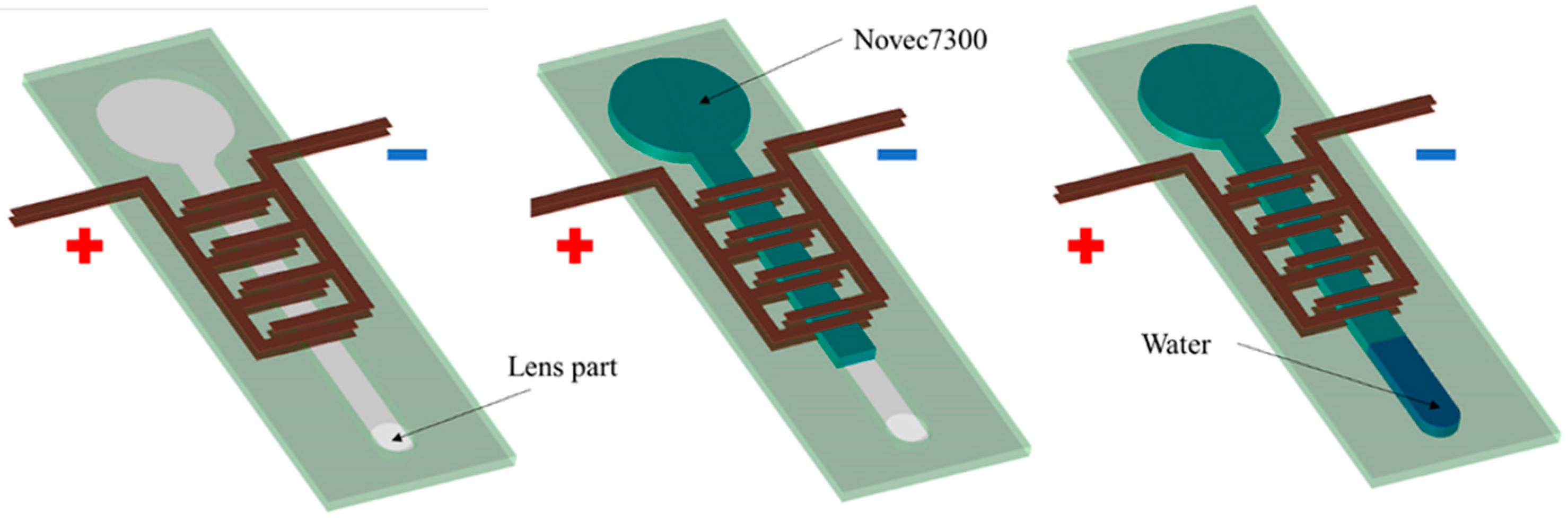
2.1. EHD Pump
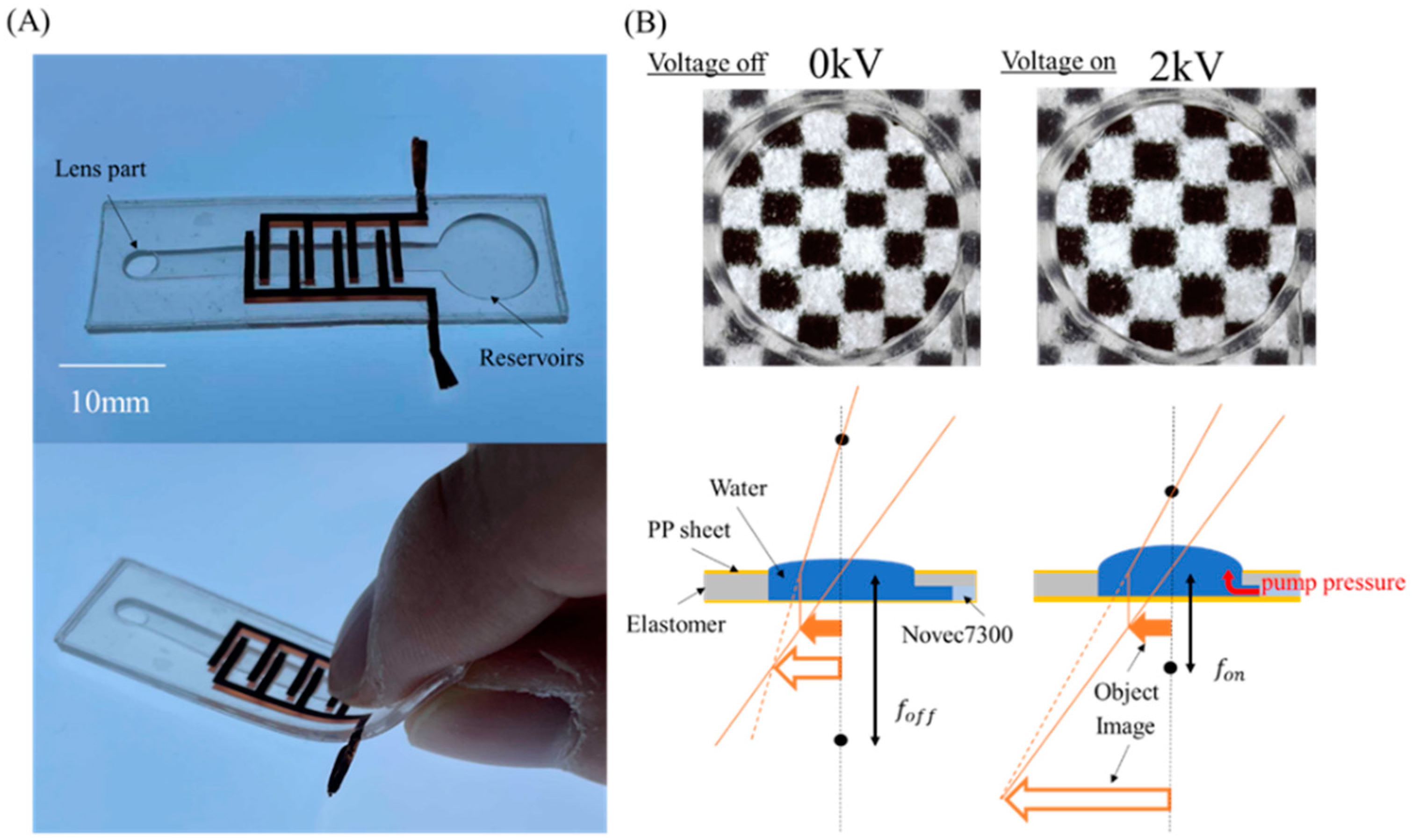
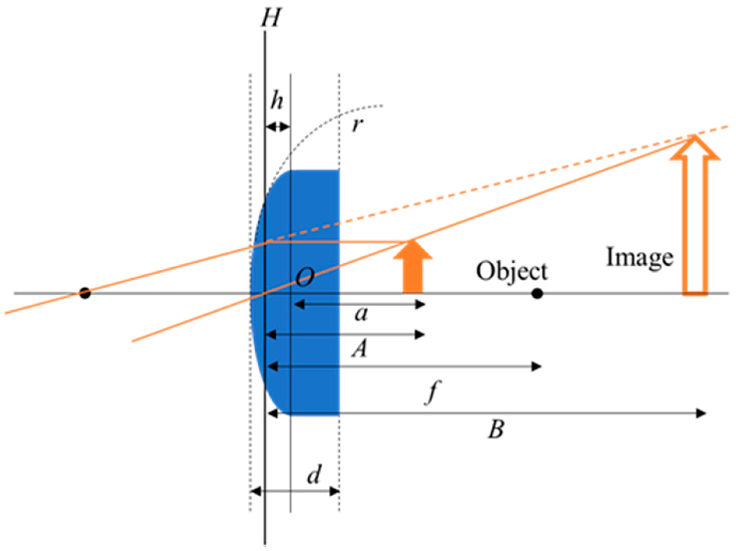
2.2. EHD Lens
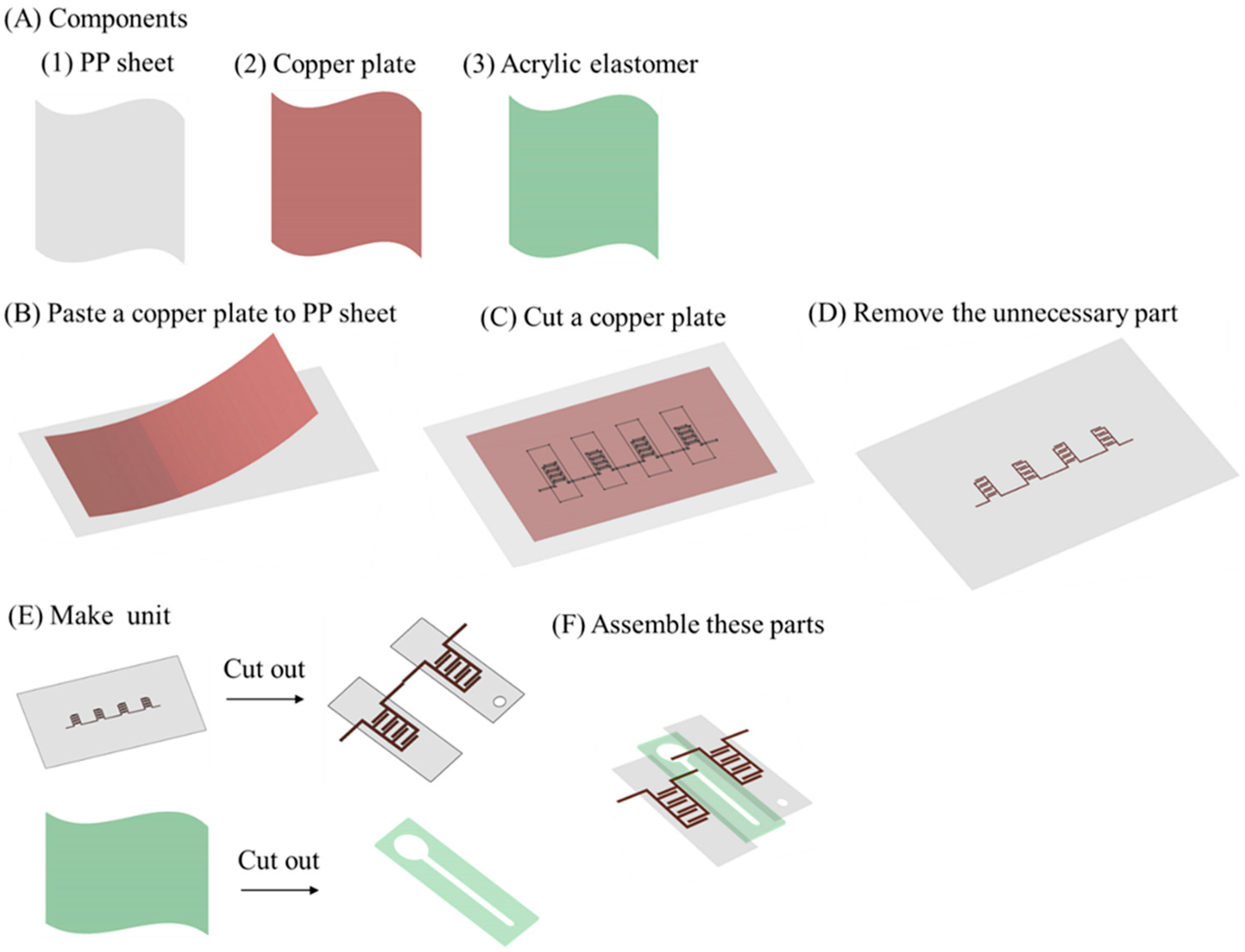
3. Materials and Methods
4. Results and Discussion
4.1. Image Focus Test of EHD Lens
4.2. Extended Performance of the EHD Lens
4.3. Demonstration of the EHD Lens
5. Conclusions
Supplementary Materials
Author Contributions
Funding
Institutional Review Board Statement
Informed Consent Statement
Conflicts of Interest
References
- Young, G.O. Synthetic structure of industrial plastics (Book style with paper title and editor). In Plastics, 2nd ed.; Peters, J., Ed.; McGraw-Hill: New York, NY, USA, 1964; Volume 3, pp. 15–64. [Google Scholar]
- Danakis, C.; Afgani, M.; Povey, G.; Underwood, I.; Haas, H. Using a CMOS camera sensor for visible light communication. In Proceedings of the 2012 IEEE Globecom Workshops, Anaheim, CA, USA, 3–7 December 2012; IEEE: Piscataway, NJ, USA; pp. 1244–1248. [Google Scholar]
- Ren, H.; Xianyu, H.; Xu, S.; Wu, S.-T. Adaptive dielectric liquid lens. Opt. Express 2008, 16, 14954. [Google Scholar] [CrossRef]
- Zhang, D.-Y.; Lien, V.; Berdichevsky, Y.; Choi, J.; Lo, Y.-H. Fluidic adaptive lens with high focal length tunability. Appl. Phys. Lett. 2003, 82, 3171–3172. [Google Scholar] [CrossRef]
- Keong, G.-K.; La, T.-G.; Shiau, L.-L.; Tan, A.W.-Y. Challenges of using dielectric elastomer actuators to tune liquid lens. In Proceedings of the SPIE Smart Structures and Materials + Nondestructive Evaluation and Health Monitoring, San Diego, CA, USA, 9–13 March 2014; Bar-Cohen, Y., Ed.; p. 90561J. [Google Scholar]
- Ren, H.; Wu, S.-T. Adaptive Lenses Based on Soft Electroactive Materials. Appl. Sci. 2018, 8, 1085. [Google Scholar] [CrossRef] [Green Version]
- Kuiper, S.S.; Hendriks, B.H.W. Variable-focus liquid lens for miniature cameras. Appl. Phys. Lett. 2004, 85, 1128–1130. [Google Scholar] [CrossRef] [Green Version]
- Ober, M.S.; Dermody, D.; Maillard, M.; Amiot, F.; Malet, G.; Burger, B.; Woelfle-Gupta, C.; Berge, B. Development of Biphasic Formulations for Use in Electrowetting-Based Liquid Lenses with a High Refractive Index Difference. ACS Comb. Sci. 2018, 20, 554–566. [Google Scholar] [CrossRef] [PubMed]
- Xu, S.; Lin, Y.-J.; Wu, S.-T. Dielectric liquid microlens with well-shaped electrode. Opt. Express 2009, 17, 10499–10505. [Google Scholar] [CrossRef] [PubMed]
- Cheng, C.-C.; Yeh, J.A. Dielectrically actuated liquid lens. Opt. Express 2007, 15, 7140. [Google Scholar] [CrossRef]
- Park, I.S.; Park, Y.; Oh, S.H.; Yang, J.W.; Chung, S.K. Multifunctional liquid lens for variable focus and zoom. Sens. Actuators A Phys. 2018, 273, 317–323. [Google Scholar] [CrossRef]
- Cheng, H.-C.; Xu, S.; Liu, Y.; Levi, S.; Wu, S.-T. Adaptive mechanical-wetting lens actuated by ferrofluids. Opt. Commun. 2011, 284, 2118–2121. [Google Scholar] [CrossRef]
- Dong, L.; Agarwal, A.K.; Beebe, D.J.; Jiang, H. Adaptive liquid microlenses activated by stimuli-responsive hydrogels. Nat. Cell Biol. 2006, 442, 551–554. [Google Scholar] [CrossRef]
- Mao, Z.; Kuroki, M.; Otsuka, Y.; Maeda, S. Contraction waves in self-oscillating polymer gels. Extreme Mech. Lett. 2020, 39, 100830. [Google Scholar] [CrossRef]
- Thongking, W.; Wiranata, A.; Minaminosono, A.; Mao, Z.; Maeda, S. Soft robotic gripper based on multi-layers of dielectric elastomer actuators. J. Robot. Mechatronics 2021, 33, 968–974. [Google Scholar] [CrossRef]
- Wiranata, A.; Maeda, S. A Deformable Linear Dielectric Elastomer Actuator. Key Eng. Mater. 2021, 884, 430–436. [Google Scholar] [CrossRef]
- Wiranata, A.; Ishii, Y.; Hosoya, N.; Maeda, S. Simple and Reliable Fabrication Method for Polydimethylsiloxane Dielectric Elastomer Actuators Using Carbon Nanotube Powder Electrodes. Adv. Eng. Mater. 2021, 23, 2001181. [Google Scholar] [CrossRef]
- Seki, Y.; Kuwajima, Y.; Shigemune, H.; Yamada, Y.; Maeda, S. Optimization of the electrode arrangement and reliable fabrication of flexible ehd pumps. J. Robot. Mechatronics 2020, 32, 939–946. [Google Scholar] [CrossRef]
- Mao, Z.; Iizuka, T.; Maeda, S. Bidirectional electrohydrodynamic pump with high symmetrical performance and its application to a tube actuator. Sens. Actuators A Phys. 2021, 332, 113168. [Google Scholar] [CrossRef]
- Scott, G.; Chin, J. A DIY approach to pervasive computing for the Internet of Things: A smart alarm clock. In Proceedings of the 2013 5th Computer Science and Electronic Engineering Conference (CEEC), Colchester, UK, 17–18 September 2013; IEEE: Piscataway, NJ, USA; pp. 57–60. [Google Scholar]
- Wiranata, A.; Ohsugi, Y.; Minaminosono, A.; Mao, Z.; Kurata, H.; Hosoya, N.; Maeda, S. A DIY Fabrication Approach of Stretchable Sensors Using Carbon Nano Tube Powder for Wearable Device. Front. Robot. AI 2021, 8, 773056. [Google Scholar] [CrossRef]
- Pearson, M.R.; Seyed-Yagoobi, J. Experimental study of EHD conduction pumping at the meso- and micro-scale. J. Electrost. 2011, 69, 479–485. [Google Scholar] [CrossRef]
- Kuwajima, Y.; Shigemune, H.; Cacucciolo, V.; Cianchetti, M.; Laschi, C.; Maeda, S. Active suction cup actuated by ElectroHydroDynamics phenomenon. In Proceedings of the 2017 IEEE/RSJ International Conference on Intelligent Robots and Systems (IROS), Vancouver, BC, Canada, 24–28 September 2017; IEEE: Piscataway, NJ, USA; pp. 470–475. [Google Scholar]
- Cacucciolo, V.; Shintake, J.; Kuwajima, Y.; Maeda, S.; Floreano, D.; Shea, H. Stretchable pumps for soft machines. Nat. Cell Biol. 2019, 572, 516–519. [Google Scholar] [CrossRef]
- Holladay, J.T.; Maverick, K.J. Relationship of the actual thick intraocular lens optic to the thin lens equivalent. Am. J. Ophthalmol. 1998, 126, 339–347. [Google Scholar] [CrossRef]
- Iulian, O.; Stefaniu, A.; Ciocirlan, O.; Fedeleş, A. Refractive index in binary and ternary mixtures with diethylene glycol, 1, 4-dioxane and water between 293.15-313.15 k. UPB Sci. Bull. Ser. B Chem. Mater. Sci. 2010, 72, 37–44. [Google Scholar]
- Kingslake, R. Optical System Design; Academic Press: Cambridge, MA, USA, 1983. [Google Scholar]
- Qin, Z.; Rong, X.; Rong, S. Images segmentation of feeding or discharging in jaw crusher based on network edition software ImageJ. In Proceedings of the 2011 International Conference on Multimedia Technology, Hangzhou, China, 26–28 July 2011; IEEE: Piscataway, NJ, USA; pp. 3109–3111. [Google Scholar]
- Areias, P.; Rodrigues, H.; Rabczuk, T. Coupled finite-element/topology optimization of continua using the Newton-Raphson method. Eur. J. Mech.—A/Solids 2021, 85, 104117. [Google Scholar] [CrossRef]
- Li, J.; Baird, G.; Lin, Y.-H.; Ren, H.; Wu, S.-T. Refractive-index matching between liquid crystals and photopolymers. J. Soc. Inf. Disp. 2005, 13, 1017. [Google Scholar] [CrossRef]
- Stupar, D.Z.; Bajic, J.S.; Joza, A.V.; Dakic, B.M.; Slankamenac, M.P.; Zivanov, M.B.; Cibula, E. Remote monitoring of water salinity by using side-polished fiber-optic U-shaped sensor. In Proceedings of the 2012 15th International Power Electronics and Motion Control Conference (EPE/PEMC), Novi Sad, Serbia, 4–6 September 2012; IEEE: Piscataway, NJ, USA; pp. LS4c.4-1–LS4c.4-5. [Google Scholar]
- Fish, R.M.; Geddes, L.A. Conduction of Electrical Current to and Through the Human Body: A Review. Eplasty 2009, 9, 15. [Google Scholar]


Publisher’s Note: MDPI stays neutral with regard to jurisdictional claims in published maps and institutional affiliations. |
© 2021 by the authors. Licensee MDPI, Basel, Switzerland. This article is an open access article distributed under the terms and conditions of the Creative Commons Attribution (CC BY) license (https://creativecommons.org/licenses/by/4.0/).
Share and Cite
Murakami, T.; Kuwajima, Y.; Wiranata, A.; Minaminosono, A.; Shigemune, H.; Mao, Z.; Maeda, S. A DIY Fabrication Approach for Ultra-Thin Focus-Tunable Liquid Lens Using Electrohydrodynamic Pump. Micromachines 2021, 12, 1452. https://doi.org/10.3390/mi12121452
Murakami T, Kuwajima Y, Wiranata A, Minaminosono A, Shigemune H, Mao Z, Maeda S. A DIY Fabrication Approach for Ultra-Thin Focus-Tunable Liquid Lens Using Electrohydrodynamic Pump. Micromachines. 2021; 12(12):1452. https://doi.org/10.3390/mi12121452
Chicago/Turabian StyleMurakami, Taichi, Yu Kuwajima, Ardi Wiranata, Ayato Minaminosono, Hiroki Shigemune, Zebing Mao, and Shingo Maeda. 2021. "A DIY Fabrication Approach for Ultra-Thin Focus-Tunable Liquid Lens Using Electrohydrodynamic Pump" Micromachines 12, no. 12: 1452. https://doi.org/10.3390/mi12121452