1. Introduction
Electrowetting is the phenomenon of modulating surface wettability via an external electric field, which has drawn great attention in lab-on-a-chip microfluidics [
1]. Electrowetting display (EWD) uses electrowetting to control the state of oil inks and display desired images, which has been at the center of attention since 2003, when Hayes and Feenstra reported on the possibilities contained in the system [
2]. The road since then has been long and arduous. A plethora of challenges have required solving one by one. Research was later focused on the prediction of the working principle, dielectric material preparation, pixel structure design, electric signal modulation and color panel realization in order to achieve market applications and mass production.
In display theory, the basic principle of electrowetting has been demonstrated to apply in confined pixels. The surface wettability change between the hydrophobic (oleophilic) state and hydrophilic (oleophobic) state causes a switch between the “on” and “off” status in each pixel unit. Tang et al. [
3] illuminated the mechanism of oil film opening and predicted the threshold voltage based on the electro-capillary instability of the oil–water interface in the pixel. Zhou et al. [
4] formulated a theoretical model of dynamic electrowetting display to predict the opening rate of oil film.
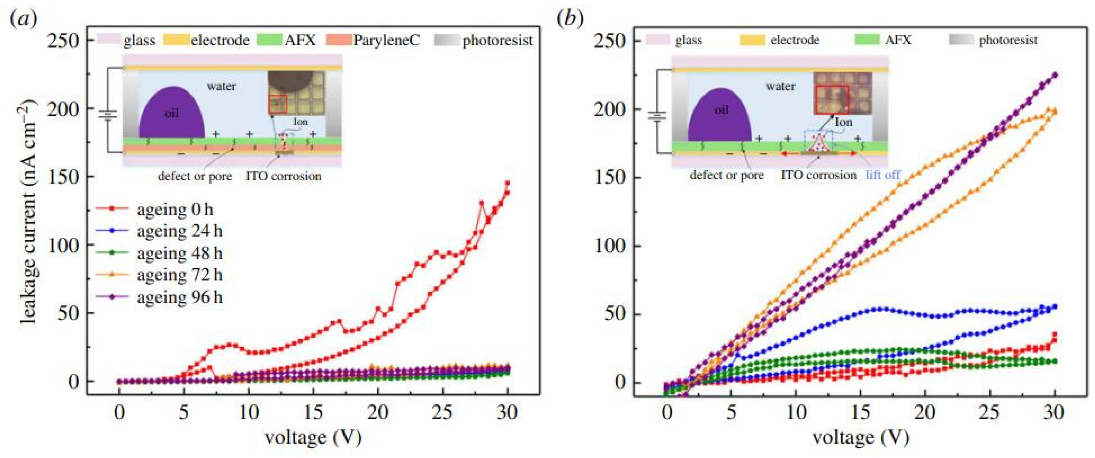
Researchers have also dedicated efforts to the development of robust dielectric materials, as the deterioration of the dielectric layer will directly lead to the failure of the display device and greatly reduce the service time. The current preparation of dielectric layers is a lengthy and error-prone process which includes sample cleaning, film coating, surface treatment and photolithographic patterning [
5]. Chen et al. [
6] reported the advantages of screen printing techniques for preparing uniform and compact dielectric materials as compared with the conventional spin coating process. Guo et al. [
7] selectively injected a fluoropolymer to form hydrophobic patterns based on a combined approach of inkjet printing and phase change filling. In this way, changes to the material properties during the surface treatment of reactive ion etching were avoided. These technical developments enabled the fast preparation of uniform and compatible multi-layer dielectrics.
A well-designed shape and structure of pixel guide the flows of oil inks in the confined system which resolve display defects. Early studies mainly focused on the planar surfaces by varying the shape and size of the pixel to restrict the fluid flow in the display unit [
8]. Various shapes of the pixel, including quadrilateral, rectangle, triangle and trapezoid shapes were designed and the response rates and brightness of the images produced were compared. The quadrilateral pixel has a better response rate and brightness, but the improvement is still limited. Additionally, the planar surface still relies on the electric signal, while displaying images in case of backflows [
9]. For a limited pixel size and spacing, overflows of the oil inks [
10] to the adjacent pixels may take place. Three-dimensional structures reserve excess oil inks and prevent oil backflows and overflows, while the bi-stable features only require electric energy during image conversion, thus, enabling them to be used for a longer time [
11]. In addition, “symmetry breaking structure” [
12] on the original planar surface realizes the breaking of the oil film under a low voltage and ensures the oil ink flows in a uniform direction.
For application of the electric signal, a proper driving waveform can not only achieve a good optical performance, but also improves the stability of the gray level [
13]. The display performance refers to the image quality (e.g., reflectivity, brightness, resolution). Optical stability means that the generated picture will not fluctuate in a certain period of time. The optical performance and stability of EWD are mainly dependent on the electro-fluidic behaviors of oil inks in the pixel. Generally, a higher opening rate and larger aperture ratio are achieved by a larger driving voltage. However, a large voltage may cause oil splitting [
14,
15]. Conversely, lower voltages can ensure more stable oil ink flows and prevent the breakdown of the dielectric layer. Therefore, the selection of electric voltage requires a tradeoff between performance and stability. A proper electric driving scheme can achieve both expectations in the real operation. By using frequency-and-amplitude modulation and converting a constant voltage to several segments, Yi et al. [
16] achieved both high levels of brightness and optical stability and also improved the response speed of oil inks.
Current challenges for electrowetting displays are mainly related to dielectric deterioration, display defects, energy consumption in mono-stable states and color panel realization. In the following sections, the electrowetting principles in the confined configuration will be introduced. The failure mode of the dielectric layer will be analyzed in more details. Suitable pixel structures and driving schemes will be discussed to achieve high performance, optical stability and energy saving displays. Lastly, the latest status and highlights of R&D will be elaborated on in this article, providing the latest insights in the behavior of oil films in pixels, and the creation of colorful images.
2. Principles: Electrowetting in Confined Systems
Electrowetting produces its active influence by changing surface wettability using an external electric field. This effect can be used to control the contact angle of the electrolyte on a solid surface, which was first described in Young–Lippmann’s equation [
17].
where
is the initial contact angle,
is the contact angle after applying electrowetting.
(=
) is the capacitance.
is the vacuum permittivity.
and
are the relative permittivity and thickness of the dielectric layer, respectively.
is the interfacial tension between the liquid and vapor and
V is the applied voltage. For a large capacitance material, the contact angle can be greatly reduced via a relatively small voltage, which results in a surface wettability change from hydrophobic (oleophilic) to hydrophilic (oleophobic).
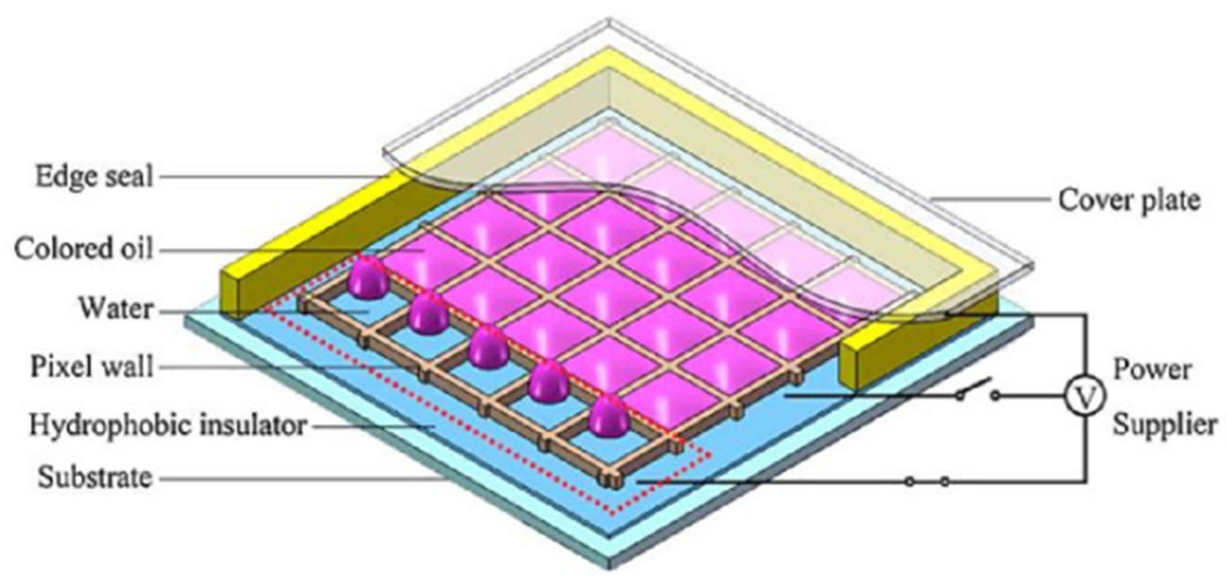
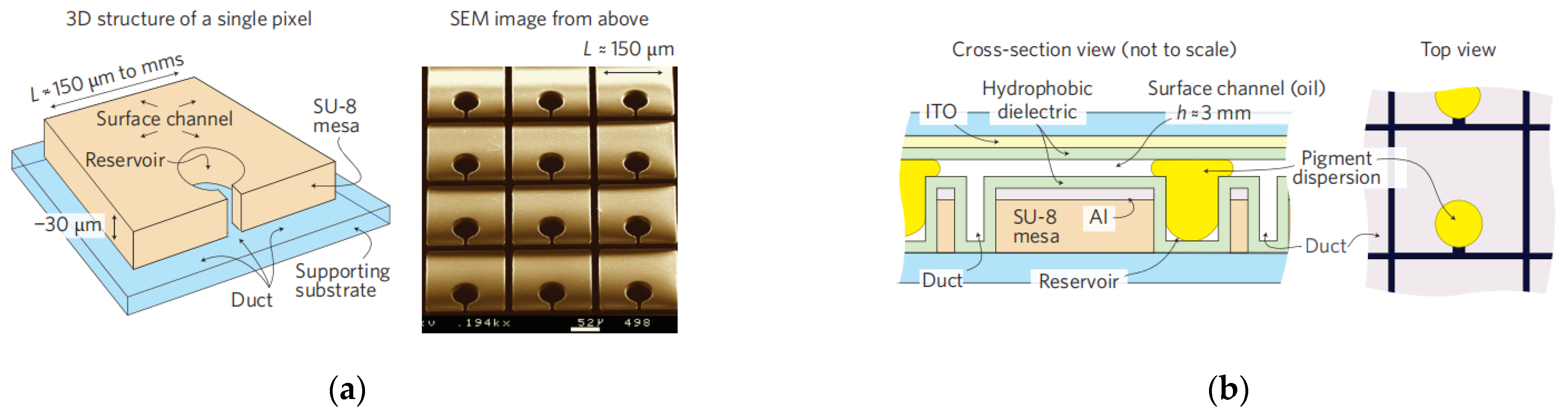
In electrowetting displays, two types of fluid exist in the confined unit; electrically insulating oil inks and electrically conductive liquid electrolytes (e.g., DI water) in the surrounding environment. Surface wettability plays a crucial role in the process of modulating the state of oil inks in order to change the aperture ratio of the pixel. A typical unit of the pixel is schematically shown in
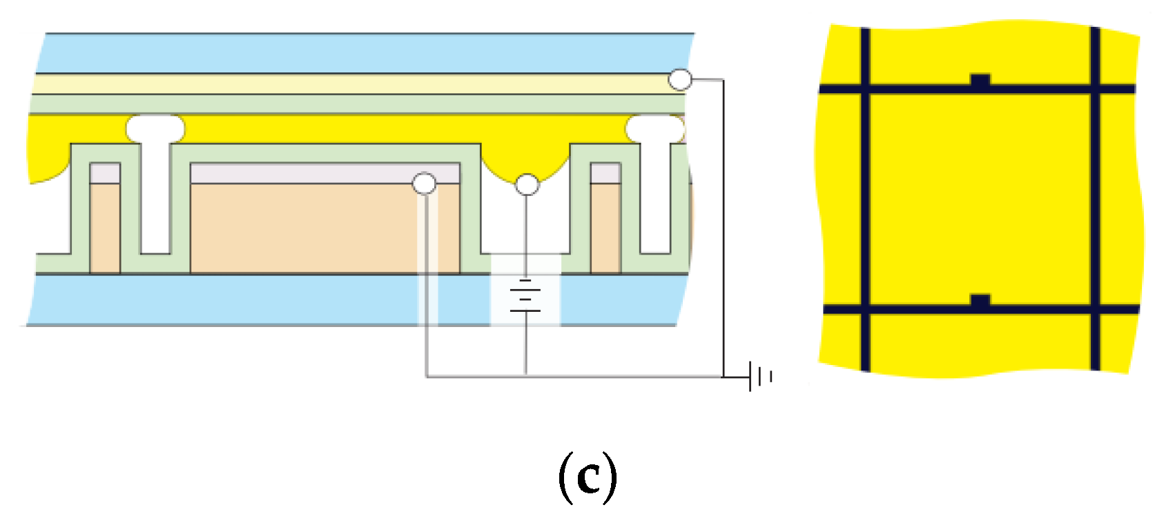
Figure 1. In
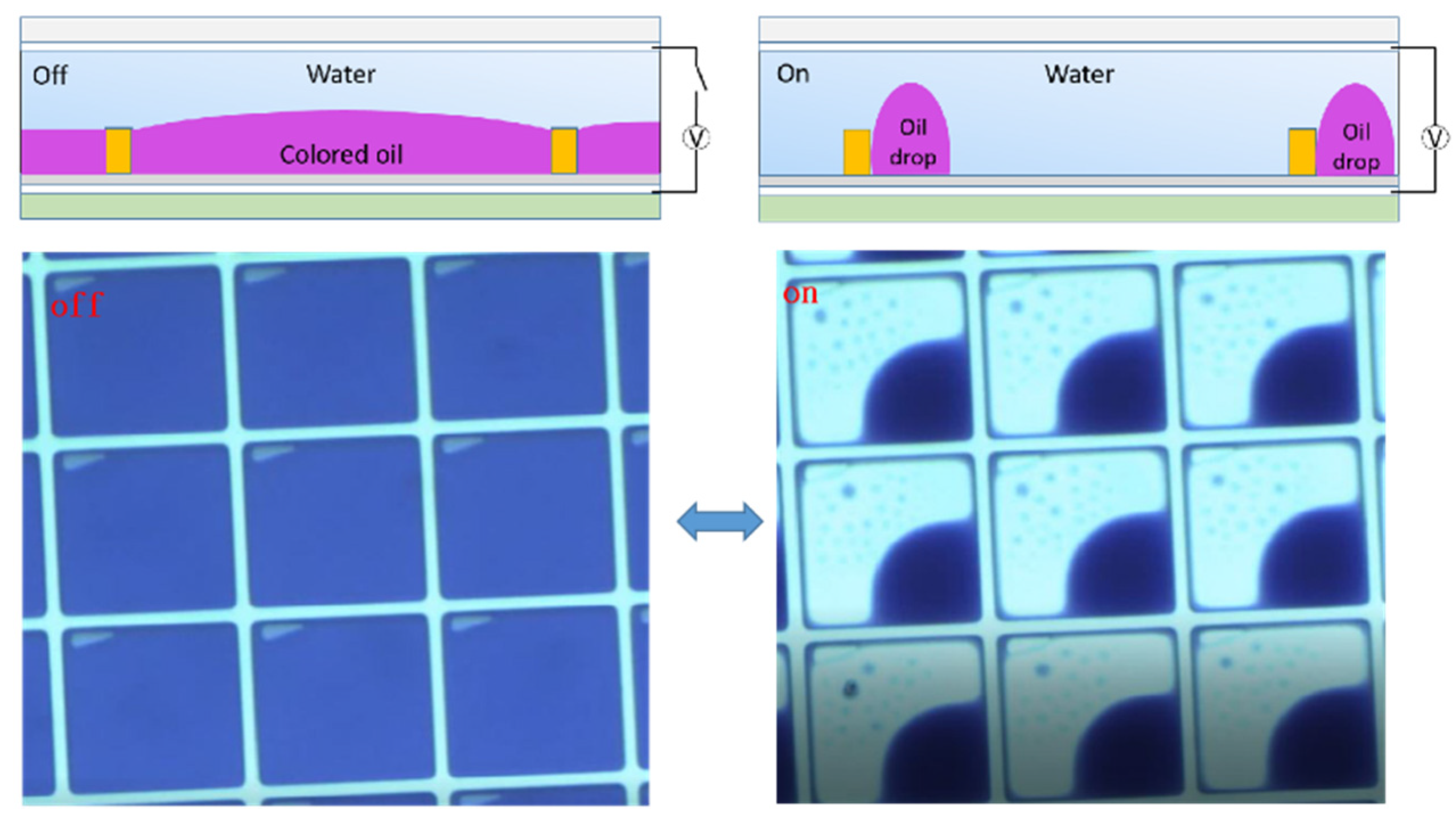
Figure 2, the oil ink is initially filled in and completely covers each pixel unit. Once the electric signal is applied, the oil film recoils and an aqueous phase occupies the open section of the pixel. The electro-capillary instability was considered in the initial opening of oil films in electro-fluidic displays [
3]. It was derived from the pressure balance on the oil-and-water interface, including the capillary pressure to maintain a flat interface and the electric stress to undulate the interface.
represents the total force pressure considering a reference pressure of
.
A positive value of this pressure promotes film growth.
is the real-time interfacial location.
is the second derivative of the capacitance of the oil film with an undisturbed thickness of
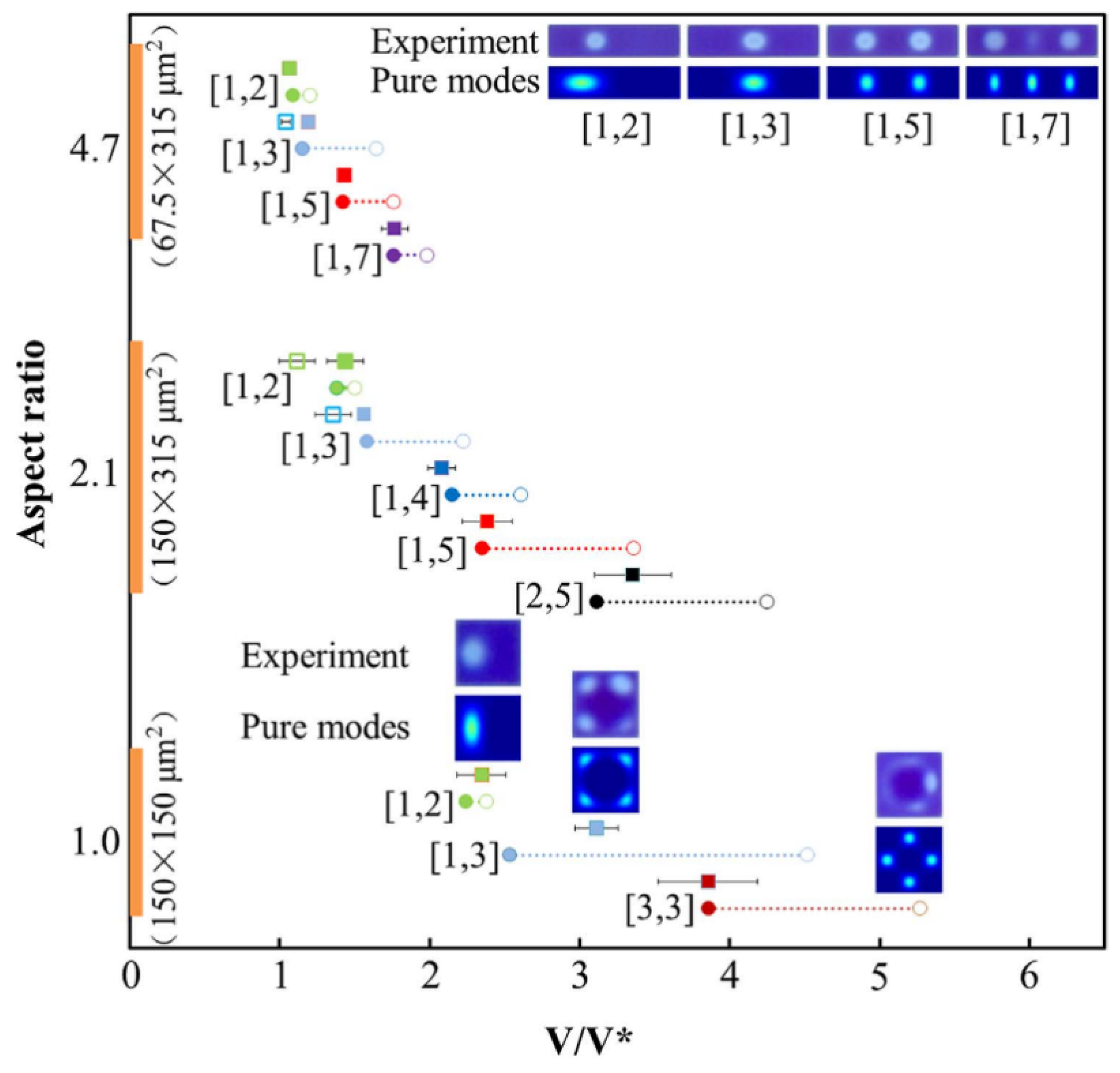
h. In
Figure 3, it is theoretically shown that the applied electric signal leads to the generation of a cascade of voltage dependent wave modes. A large voltage or a small oil film thickness will make the interface unstable, and consequently lead to the rupture of the oil film. In the course of validating the theory, it was experimentally observed that a number of undulation modes appear prior to film rupture, and the rupture location does not correspond to the maximum electric field strength in the case of the standard convex water/oil interface used in working devices. These findings provided an improved understanding of the dynamics of the oil rupture process inside the pixel after applying a voltage.
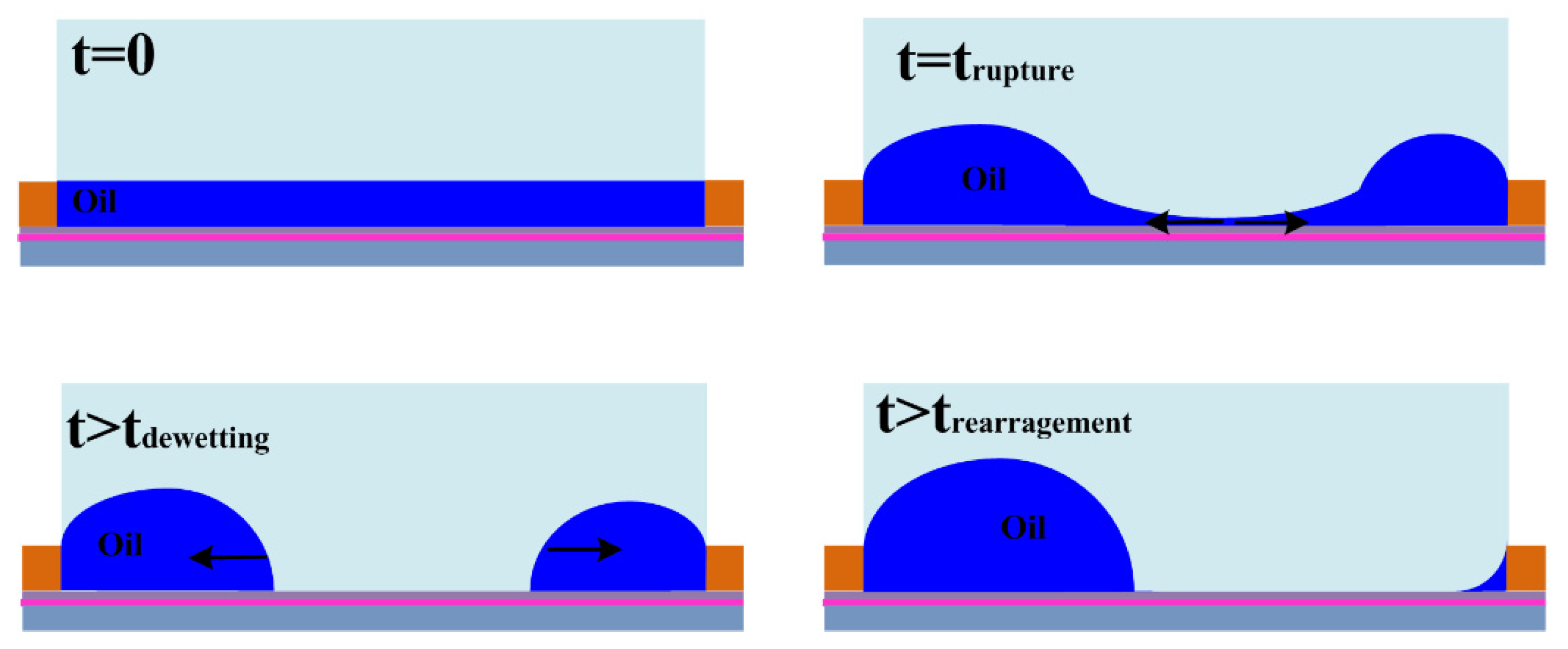
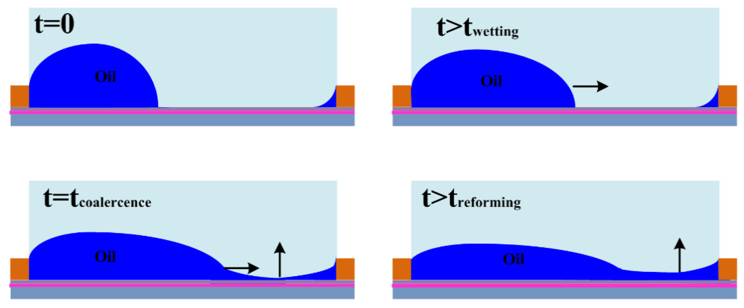
Furthermore, the dynamic behaviors of oil inks in the dewetting and rewetting processes, corresponding to the “on” and “off” switching of the pixel unit, were analyzed in an electro-fluidic pixel [
4]. For “on” switching, the oil motion leads to oil film rupture (initiation stage), oil-dewetting and a slower droplet rearrangement stage (
Figure 4). For “off” switching, fast oil wetting and reforming of the surface to the flat (dark) state (
Figure 5) occur. A dynamic model derived from the energy balance perspective has been employed to describe the electro-fluidic response and corresponding optical performance inside an electro-fluidic based display (EFD) pixel. The variability of oil ink motion between on and off-switching and the optical response delay during the on-switching process have been well described and addressed.
According to the theoretical approach of static and dynamic conditions for oil ink in confined pixels, this provided a straightforward approach to describe the complex electro-fluidic switching dynamics under electrowetting modulation, which may guide the further optimization of EFD device design and driving schemes.
5. Electrical Driving: Optimization of Opening Behavior and Greyscale Control
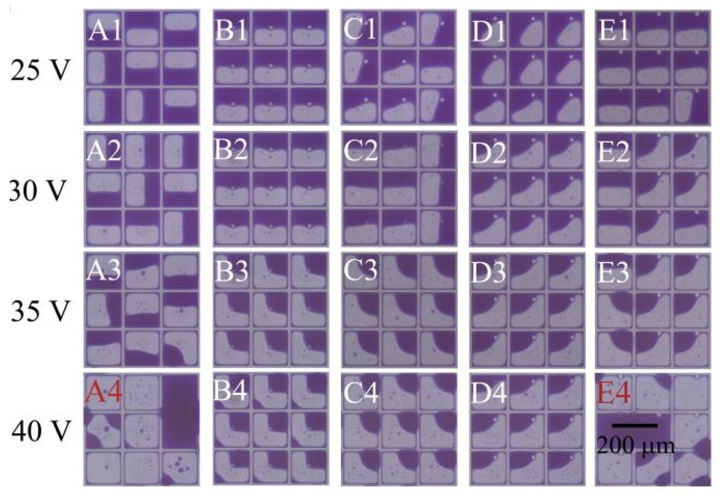
A good optical performance of an electrowetting display is realized by controlling the movement of ink under optimized driving signals. When the initial voltage is very low, the ink area is basically invariable. However, the voltage should not be too high otherwise it will cause the oil film to break into a number of small oil droplets, which reduces the display area. In addition, it can easily penetrate the hydrophobic insulation layer and damage the pixel unit.
In order to display different gray scales in an electrowetting display, a voltage sequence must be applied in order to control the gray scale. This voltage sequence is related to the driving waveform. The driving waveforms commonly used in an electrowetting display are pulse width modulation (PWM) [
23] and amplitude modulation (AM) [
16]. However, both of these methods have drawbacks. The high frame rate of conventional PWM limits the gray level and causes large visual oscillations. The disadvantage of AM method is mainly attributed to the hysteresis effect.
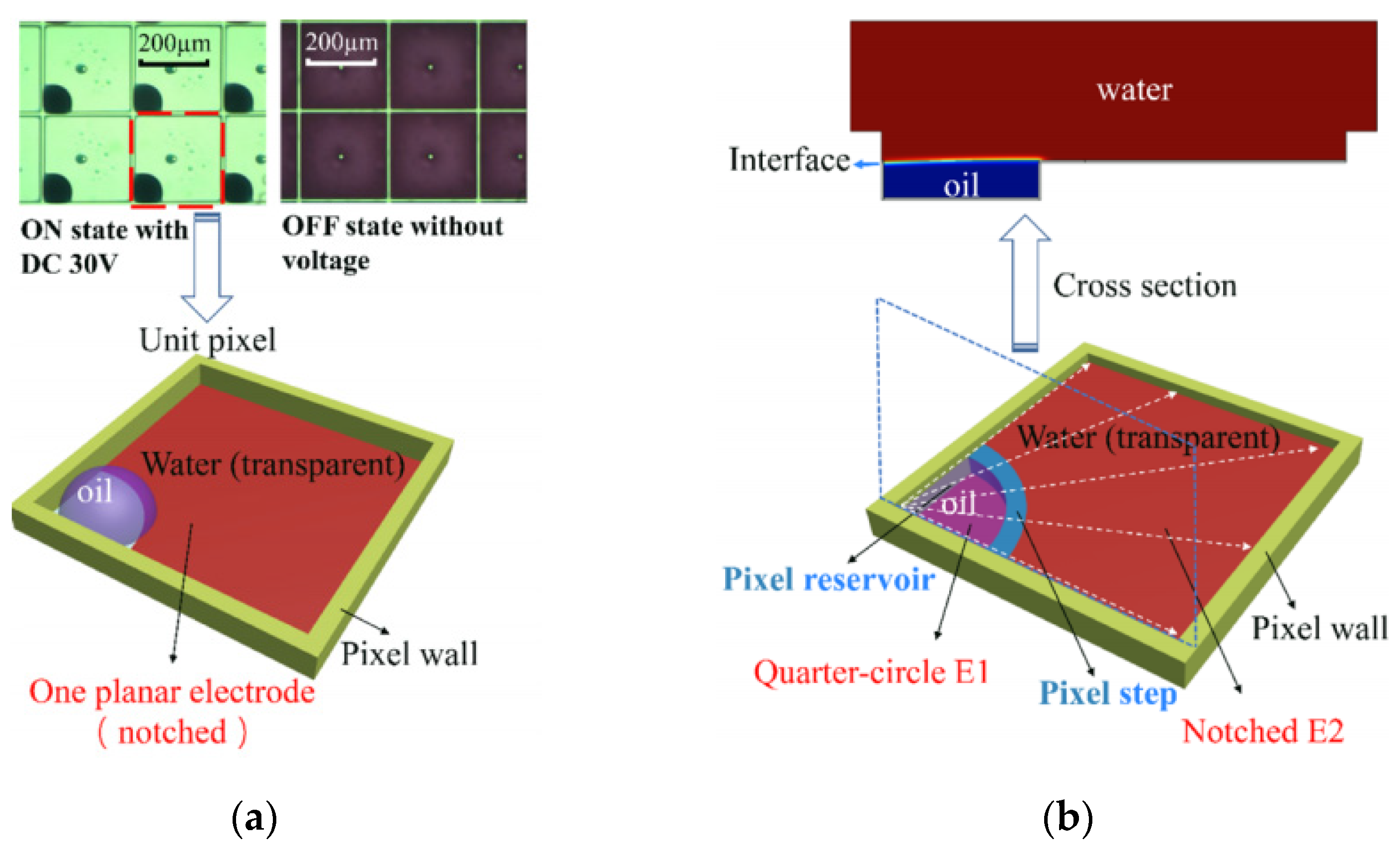
A more functional driving waveform is based on the modified PWM square waves, as shown in
Figure 11 [
24]. The faster rising rate results in a shorter ink rearrangement time after oil film rupture [
25]. When a sharp driving waveform is applied, the oil film breaks into oil drops which move to different corners; a process called oil splitting [
15]. Slow waveforms, such as sinusoidal waveforms (as shown in
Figure 11b), on the other hand, can effectively reduce the oil splitting and slowly open the pixel. However, the rising time is long, which limits the response rate. Therefore, the rising voltage waveform—as shown in
Figure 11a—that is employed to start from the threshold voltage and rise to the pixel opening voltage in the form of a sine wave, not only improves the opening rate, but also reduces the oil splitting effect.
When a voltage is applied, the oil film opens and the oil ink is pushed towards the corner of the pixel. After a certain period of time, some ions from the liquid electrolyte enter the insulation layer and are trapped, thus causing ink “backflows” [
26]. The experimental results showed that when an alternating current voltage is applied, the captured charge can be repeatedly released and recaptured [
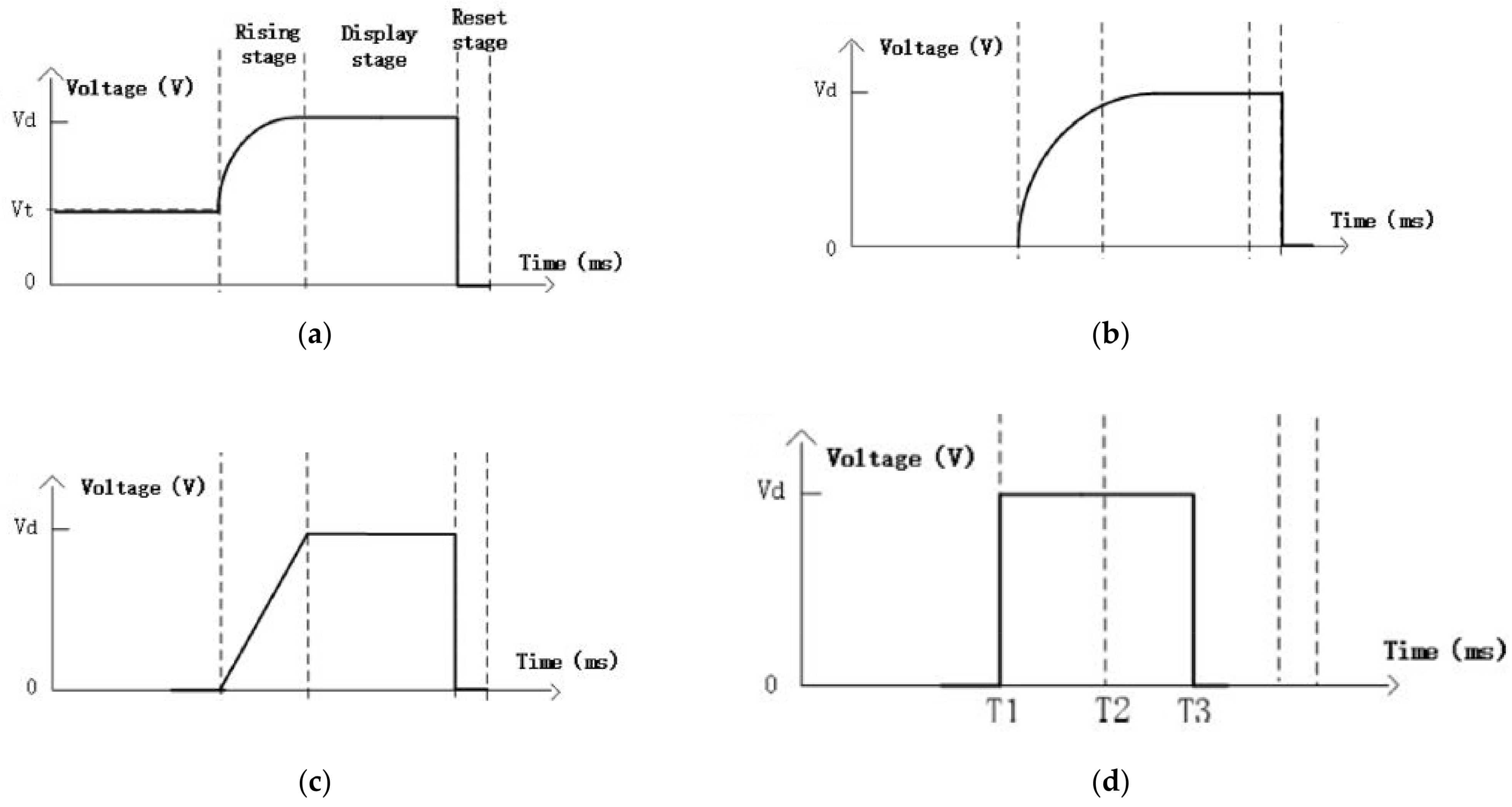
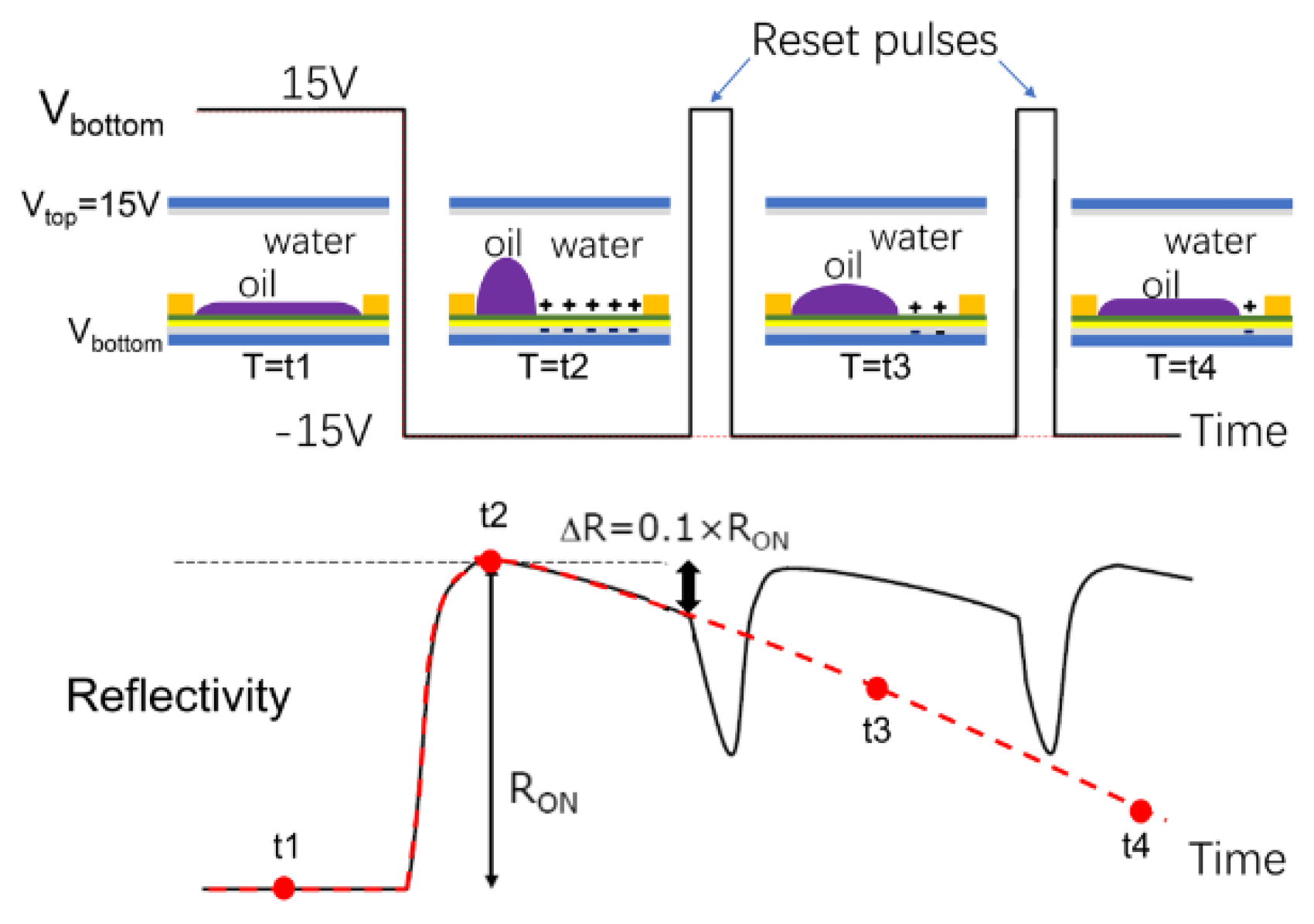
23]. Therefore, the charge capture behavior can be controlled by applying the alternating current signal so as to limit the ink backflow effect and improve the display stability. As shown in
Figure 12, an initial voltage of 15 V is applied to both upper and lower plates, the voltage difference is 0 and the oil film remains in place. When the bottom voltage changes to −15 V the pixels slowly open to show the state at T2, and the ink shrinks to the corner of the pixel. At T3, due to the charge capture, the oil droplets gradually flow back. If the reflectivity is reduced to one tenth of the maximum value, the voltage between the plates is set to 15 V. In this way, the trapped charges are neutralized. Once the signal is set to −15 V, the reflectivity will rise again. A periodic reset will ensure a stable and high reflectivity.
To provide a brief discussion of the amplitude-and-frequency modulation of the electric signal, the chosen voltage and frequency should be able to prevent the display defects (splitting, overflow and backflow) in order to improve the display performance and optical stability. Therefore, the initial voltage potential is set to a value just below the rising threshold and the applied voltage is slowly increased in the form of a sinusoidal wave. This will both improve the opening rate and reduce ink splitting and oil overflows to the adjacent pixels. The frequency of the periodic square waves is also fitted to prevent the phenomenon of ink backflow so that the pixel can maintain a constant optical reflectivity.
6. Demonstration Displays and Color Reproduction
6.1. Color Mixing
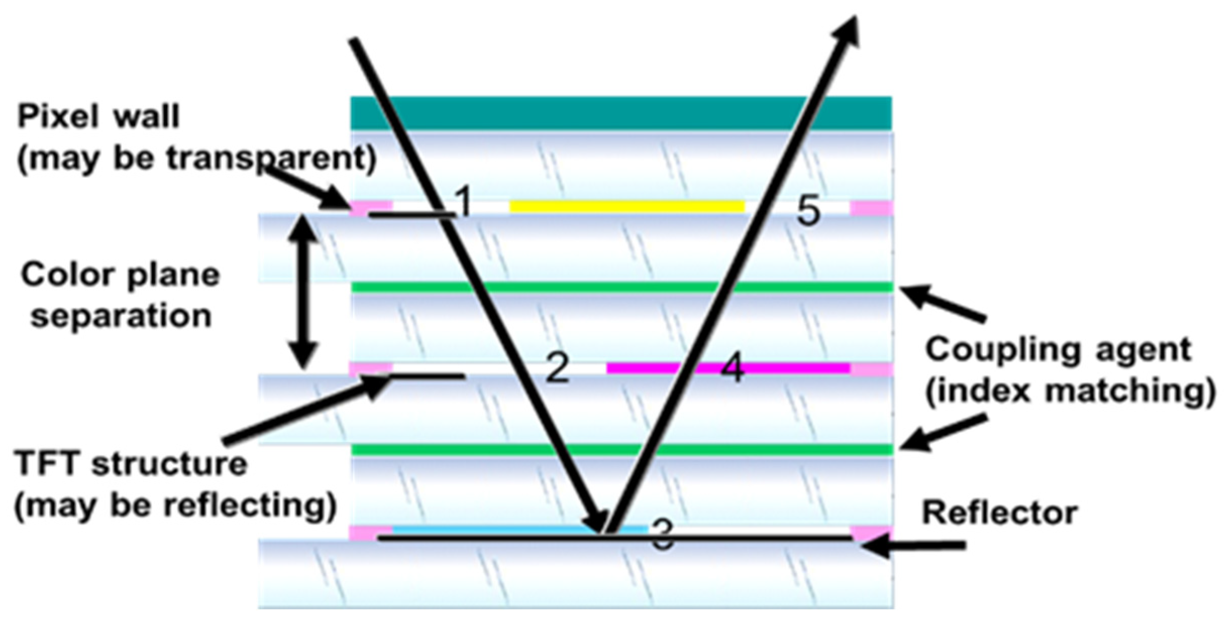
The color system for this display is based on a cyan, magenta, yellow subtractive color system. This means that three layers of color have to be assembled and separately driven. Therefore, displays have to be aligned accurately, substrate thickness has to be minimized to limit parallax (
Figure 13) and light losses have to be minimized in order to achieve brilliant colors.
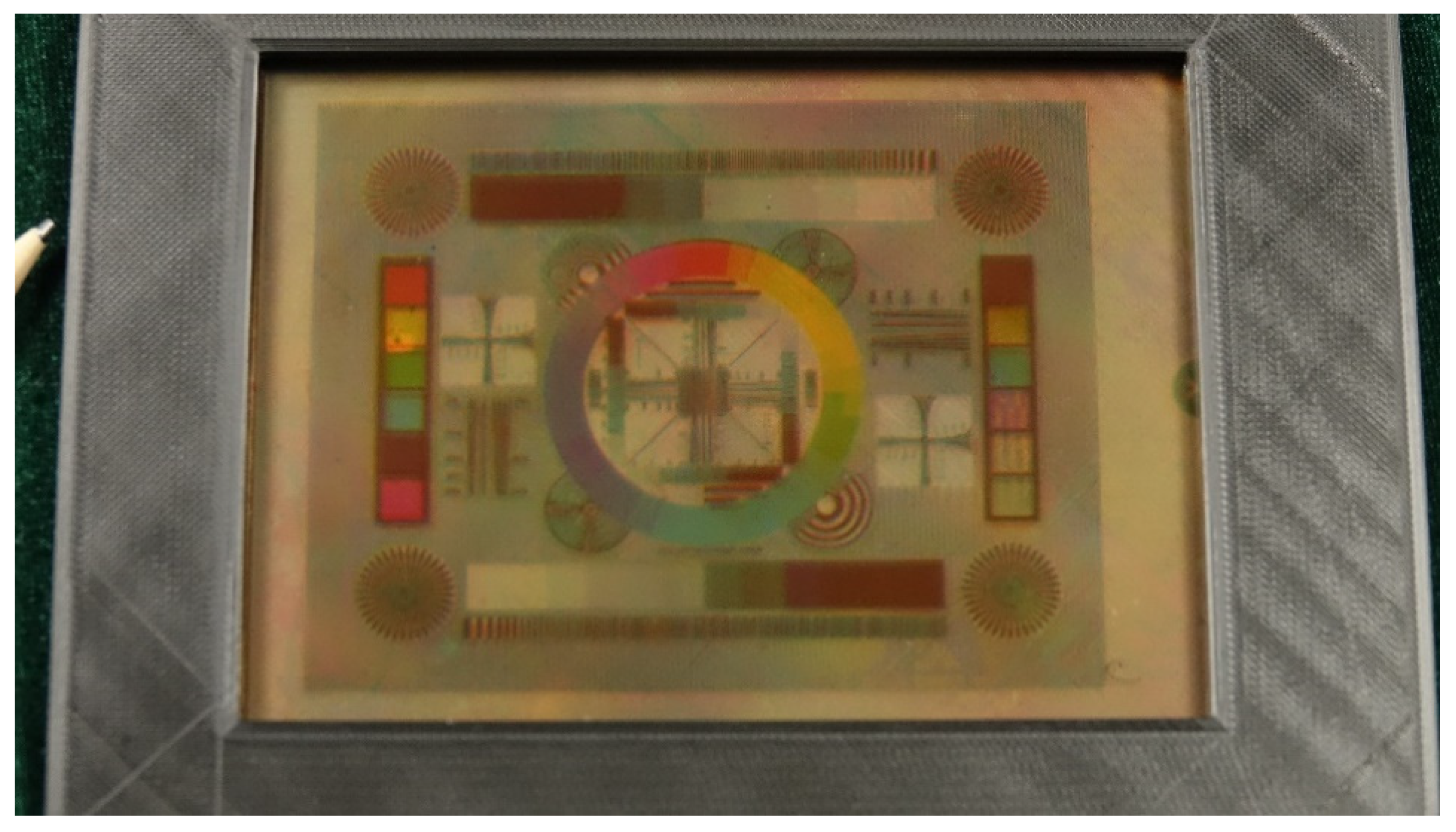
6.2. System
The target for the display demonstration is to—as much as possible—use “standard” driving equipment. In order to achieve this, the image source of the demonstrated panel consists of a standard Android system, providing standard RGB output to drive the display panels.
The adaptation is surprisingly easy, once it is realized that cyan is the complement of red, magenta is the complement of green, and yellow is the complement of blue. Therefore, by driving the cyan panel with the red signal, the signal generates exactly the right response (less “cyan” means more “red”).
Of course, some adaptation may be necessary for grayscale spacing, but this is relatively simple, and can be done by adjusting the greyscale “gamma” value. Apart from this, the system has to accommodate for the peculiarities of the electrowetting system, making sure the charge rate of the pixel does not exceed a certain limit value, as described in previous sections. Furthermore, the system makes use of the field response and low leakage current properties of the display, making it possible to refresh a still image with long intervals, thereby minimizing the power.


 ,
, 