1. Introduction
In recent years, the demand for communication capabilities has been significantly increased. Therefore, there have been many research advances in the design and implementation of multi-band, ultra-wideband, and reconfigurable antenna technologies [
1]. Compared with the multi-band and ultra-wideband antennas, at any given instant of time, the frequency reconfigurable antennas only work in a part of the entire working frequency band. Therefore, this kind of antenna has a superior noise suppression effect on the unused frequency bands.
In common solid-state circuits, switching elements such as radio frequency microelectromechanical systems (RF-MEMS) [
2], p-type intrinsic n-type (PIN) diodes [
3], and varactor diodes [
4], are often used to achieve antenna reconfiguration capability. The efficiency of these reconfigurable antennas may be limited by the application of too many semiconductor devices, which may also cause nonlinear problems. In liquid antennas (e.g., water [
5], liquid crystal [
6], transformer oil [
7], organic solvents [
8], and liquid metal [
9]), the fluidity and deformability of the fluid are employed to realize changes in the antenna geometry and its radiation characteristics. The usage of these liquid antennas has reduced the number of semiconductor switches.
For instance, in [
5], a very high frequency (VHF) seawater monopole antenna was presented for maritime wireless communications. The center frequency of this antenna can be varied between 62.5–180.2 MHz. Liquids such as water and ethyl acetate are economical, but they have a high dielectric loss at higher operational frequencies. In [
6], a liquid crystal-based frequency tunable circular ring patch antenna is designed, which achieves a tuning range of 2.427–2.532 GHz but with a gain of 0.1 dBi. To reduce losses, adopting a low-loss transformer oil has been suggested in [
7], where a frequency reconfigurable patch antenna was designed to achieve a tuning range from 1.42 GHz to 1.96 GHz.
Liquid metals have also attracted widespread attention in designing reconfigurable antennas due to their rheological and metallic properties [
10]. The deformation and actuating strategies of the liquid metal often have implications on the design, the implementation process, and the actual dimension of the reconfigurable antenna.
The existing techniques of deforming and reconstructing liquid metal can be divided into mechanical and electric actuating methods. Mechanical actuating includes, e.g., methods such as pressurization by a syringe [
11,
12,
13,
14] or a pump [
15,
16,
17], thermal expansion [
18], gravity [
19,
20], or external forces [
21,
22,
23]. Instances of electric actuating include electrochemistry [
24,
25] and capillary electrowetting [
26,
27]. There are advantages and disadvantages in those driving modes of the liquid metal. External forces [
18,
19,
20] or syringe injection [
9,
10,
11,
12] methods may not be convenient enough. Pumping methods [
13,
14,
15] often require specially designed auxiliary flow channels. In contrast, it is more convenient to use electrochemical [
24,
25] and capillary electrowetting [
26,
27] driving methods. However, due to the introduction of electrochemical reactions, the liquid metal and solution would continue to be consumed. The reconfigurable antenna designed based on the thermal expansion principle of liquid metal can achieve non-contact control [
16], but it takes a long time to stabilize the temperature and requires relatively large heating power consumption.
Under the action of gravity, the liquid flows upon the adjustment of the antenna’s position. This phenomenon seems to be an issue that should be avoided when designing a liquid antenna. However, it may be also considered as a simple, yet effective, reconfiguration method. For example, in [
19] mercury was used to design a component that is equivalent to a single-pole double-throw switch. For two different angles of +90° and −90°, the component connects different parts, realizing two working states of the antenna. However, considering the toxicity of mercury and the complexity of its processing, the researchers ended up using copper instead of mercury.
In practice, mercury was the earliest liquid metal used in antenna design [
17,
19,
28]. Currently there is a global trend to restrict using mercury [
29]. Instead, gallium, gallium-based alloys, and bismuth-based alloys are considered beneficial alternatives to mercury due to their low volatility and toxicity [
27,
30]. The melting points of gallium and common bismuth-based alloys are higher than room temperature (25 °C), so elemental gallium and bismuth-based alloys are not suitable for applications that need to remain in a liquid state at room temperature. Therefore, in this work, EGaIn (a kind of gallium-based alloy, with a melting point of 15.5 °C [
18]) was selected from many types of liquid metals. However, compared with mercury, EGaIn is more prone to oxidation [
17]. Under the action of a small amount of oxygen, a thin and dense oxide layer is formed on the surface of EGaIn and can prevent further oxidation [
31]. Additionally, this oxide layer will increase adhesion and affect the smooth flow of EGaIn [
32]. Therefore, in many studies [
12,
24,
25,
26,
27], acidic or alkaline electrolytes are used as a highly effective way to remove the oxide film of EGaIn. Here, for the same reason, a NaOH solution is used to fill a part of the patch.
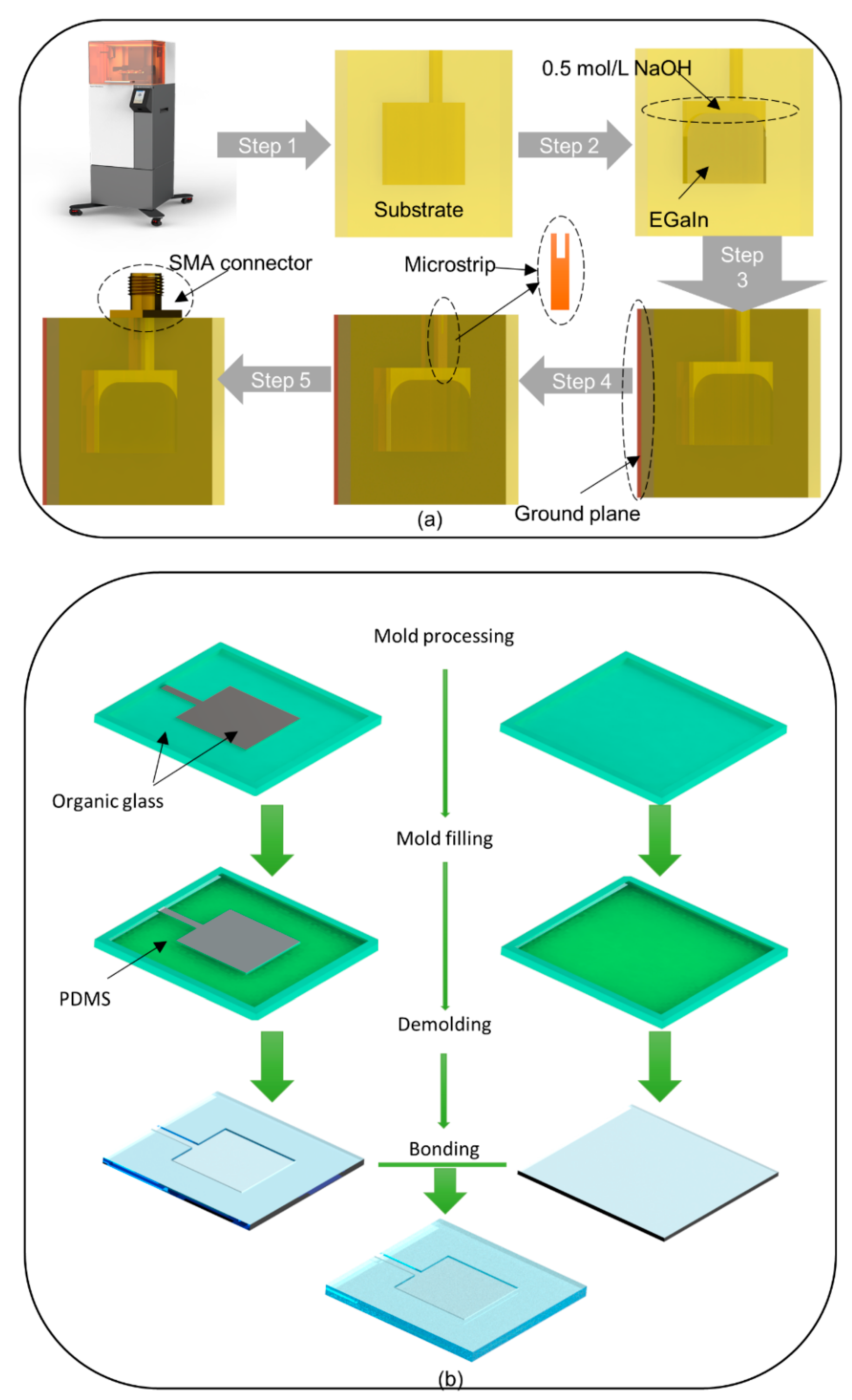
The patch antennas with a simple structure are widely used in integrated circuits, which is due to their convenient integration and cost-effectiveness. By applying the principle of liquid metal deformation under gravity, in this paper, a frequency reconfigurable microstrip antenna is proposed for the first time. The three-dimensional (3D) printing technology is then applied to fabricate the substrate in an integrated and fast approach, and the cavity of the substrate is filled with EGaIn. The antenna is rotated along the axis of the patch, resulting in the flow and deformation of the liquid metal inside the cavity. For different rotation angles, the antenna is changed to various patch shapes, and its radiation characteristics, therefore, are changed. Within a certain range of −30° to +30°, the rotation angle shows an obvious functional relationship with the resonance frequency. Therefore, the angle of rotation of the antenna could also be calculated based on the measured resonance frequency.
In addition to being a broadband reconfigurable antenna, the proposed patch antenna is a promising candidate for detecting the inclination in practical scenarios such as construction, transportation, logistics, aerospace, and robotics.
2. Antenna Design
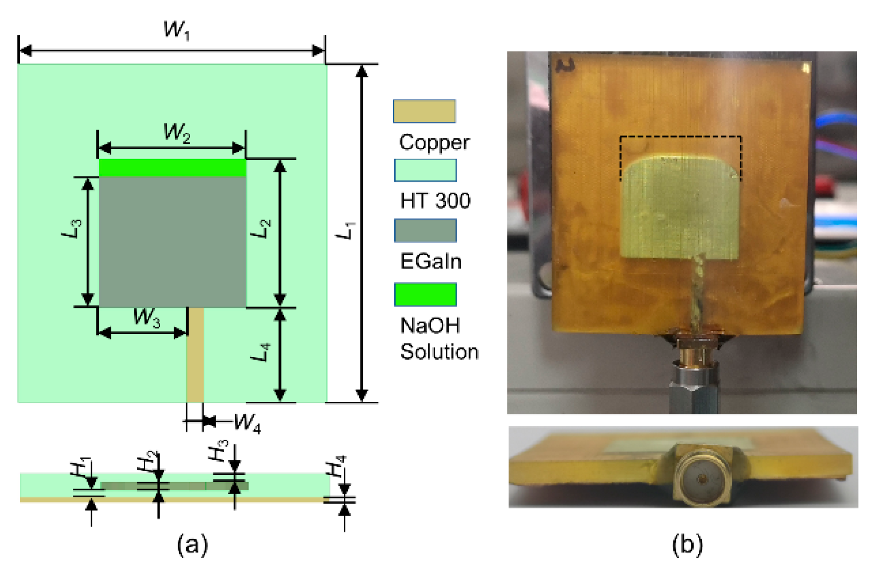
To verify the feasibility of the proposed reconstruction strategy, a simplified liquid metal patch antenna is designed. The antenna is expected to work at 4–5 GHz. It is configured in a rectangular patch structure, which is illustrated in
Figure 1. The antenna comprises of the radiation patch, the substrate, the microstrip line, the subminiature version A (SMA) connector, and a ground plane.
The radiation patch is made of EGaIn (which is a liquid metal with the composition of 75.5% gallium and 24.5% indium, and with an electrical conductivity of σ = 3.46 × 10
6 S/m [
33]), and the microstrip line is made of copper (with an electrical conductivity of σ = 5.96 × 10
7 S/m [
34]). The positions of the radiation patch and microstrip line are reserved while processing the substrate. The substrate is fabricated by 3D printing with photosensitive resin. To ensure that the hollow structure does not collapse, the radiation patch is covered with a dielectric material with a thickness of 1 mm (
H1 and
H3), and the thickness of the cavity at the center
H2 (i.e., the thickness of the radiation patch and the microstrip line) is set to 0.5 mm. Note that if
H1 and
H3 are too small, the covering layer might be easily collapsed (as shown in
Figure S1). The initial value of the patch length
L3 can be estimated by the following equation [
35]:
where
fc is the center frequency that is expected to be 4.5 GHz,
c0 is the speed of light in the vacuum, and
εr is the relative dielectric constant. The substrate material is
High Temperature® 300 (
HT® 300), which is a high-temperature resistant resin. It should be pointed out that
Figure® 4 is the name of the 3D printer that can process
HT® 300. The
Figure® 4 printer and the
HT® 300 resin are both produced by 3D Systems Corporation, Wilsonville, OR, USA.
The measured dielectric constant
εr of
HT® 300 is 2.7, and the dielectric loss tangent tan
δ is 0.01 at 4.5 GHz. The antenna works at its dominant mode TM01. The initial values
L4 (11.2 mm) and
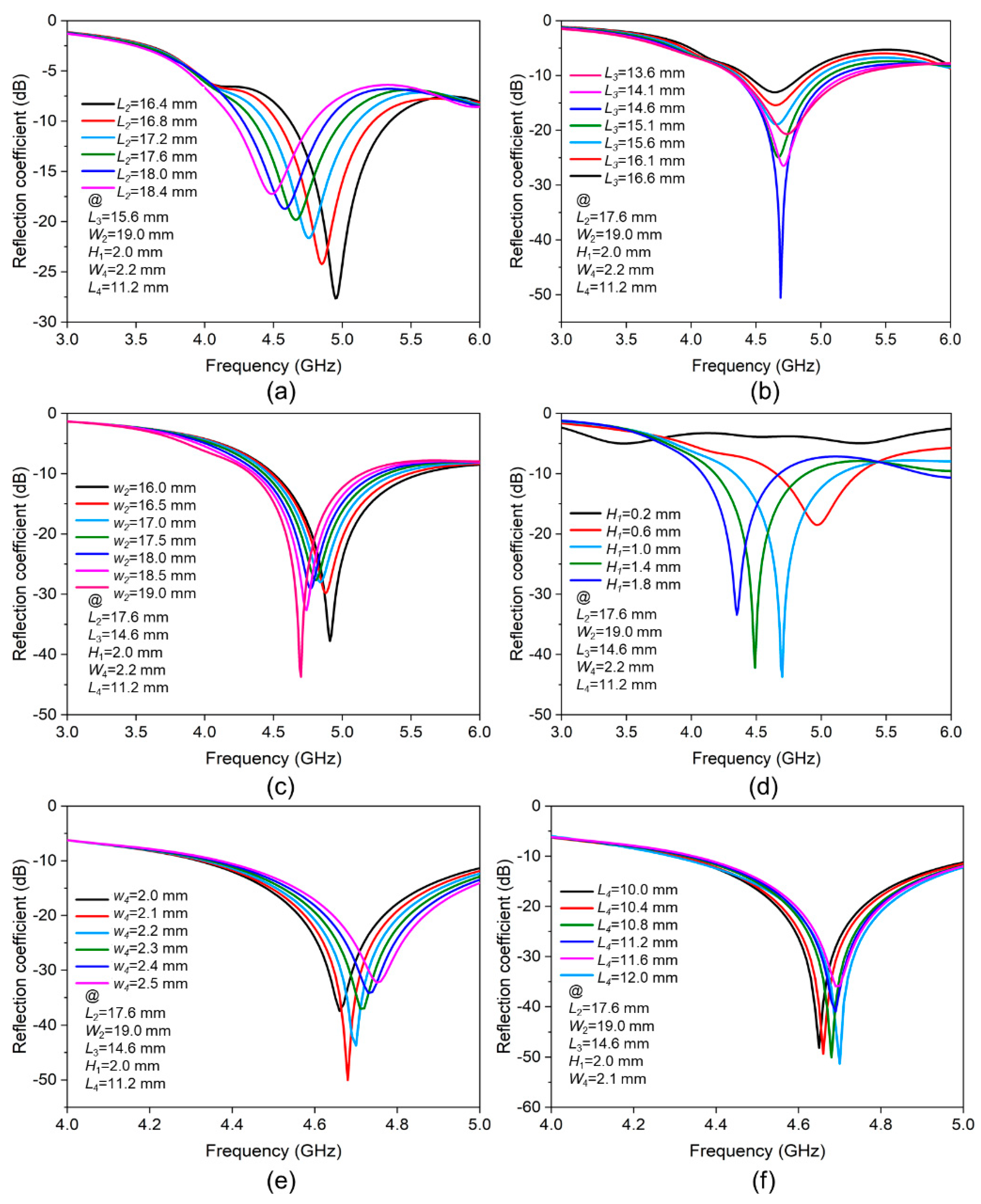
W4 (2.3 mm) of the microstrip line are exported by the transmission line calculator Txline. The obtained geometric structure is then modeled and optimized in the full-wave electromagnetic high-frequency structure simulator (HFSS). A part of the optimization process is shown in
Figure 2.
Figure 2a describes the impact of
L2 on the antenna impedance matching. Increasing
L2 can reduce the resonance frequency, but its reflection coefficient also increases, so the intermediate value of 17.6 mm is selected.
Figure 2b shows that the impedance matching is best when
L3 is equal to 14.6 mm. It can be seen from
Figure 2c that when
W2 increases and is closed to the value of
L2, the impedance matching becomes worse. However, when
W2 continues to increase, the impedance matching is improved again, so
W2 is set to 19.0 mm.
Figure 2d illustrates the influence of the thickness of the dielectric layer between the liquid metal and the ground plane (
H1) on the impedance matching of the antenna. Regardless of whether the thickness
H1 is too large or too small, it is not conducive to the antenna, so an optimized value of 1.0 mm is selected.
Figure 2e,f show the results of optimizing the width
W4 and length
L4 of the microstrip line, and they are set to 2.1 mm and 12 mm, respectively. All the optimal dimensions are presented in
Table 1.
4. Measurement of the Contact Angle
After the proposed antenna was manufactured, it is noticed that the walls of the liquid metal and the resin material are not set at the right angle, but there is a certain arc (see
Figure 1). This is because the liquid metal was not wetting the surface of the resin completely based on the NaOH solution. The quality of the wetting can be characterized by the contact angle. The smaller the contact angle is, the better the wetting effect would be. For example, if the contact angle is 0°, it means complete wetting; if the contact angle ranges between 0° and 90°, it means incomplete wetting; if the contact angle varies between 90° and 180°, it means no wetting; and, if the contact angle is equal to 180°, it means no wetting at all.
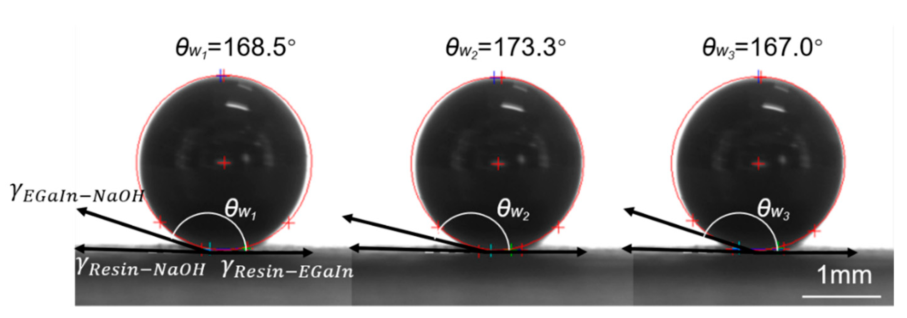
Liquid metal and NaOH solution are poured into the resin cavity, and after reaching an equilibrium state, the relationship between the contact angle and the surface tensions follows the following equation:
where γ
Resin-NaOH is the surface tension between the resin and NaOH solution, γ
Resin-EGaIn denotes the surface tension between the resin and EGaIn, γ
EGaIn-NaOH is the surface tension between EGaIn and NaOH solution, and
θw is the contact angle between the liquid metal and the resin surface.
In the 0.5 mol/L NaOH solution, the contact angle,
θw, is measured three times and shown in
Figure 4. The five-point fitting method is then used to obtain the contact angle. Finally, the average value of the three measurements, 169.6°, is taken as the contact angle. The contact angle
θw is, however, very large since the liquid metal and resin are very non-wetting. The simulation model could be approximately considered that the wall of the liquid metal and the resin are tangents, which simplifies the modeling process.
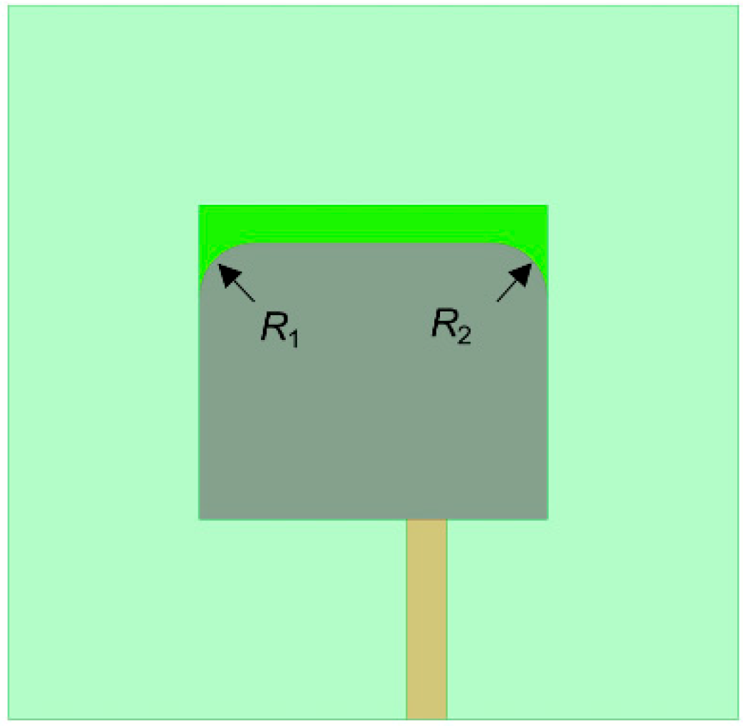
Based on the geometric structure of
Figure 1a, rounded corners
R1 (at left) and
R2 (at right) are then added to modify the geometric model. The modified model is shown in
Figure 5. To improve the accuracy of the models, for different rotation angles, the simulation models are revised according to the sizes of the actual objects
R1 and
R2.
5. Rotating Method
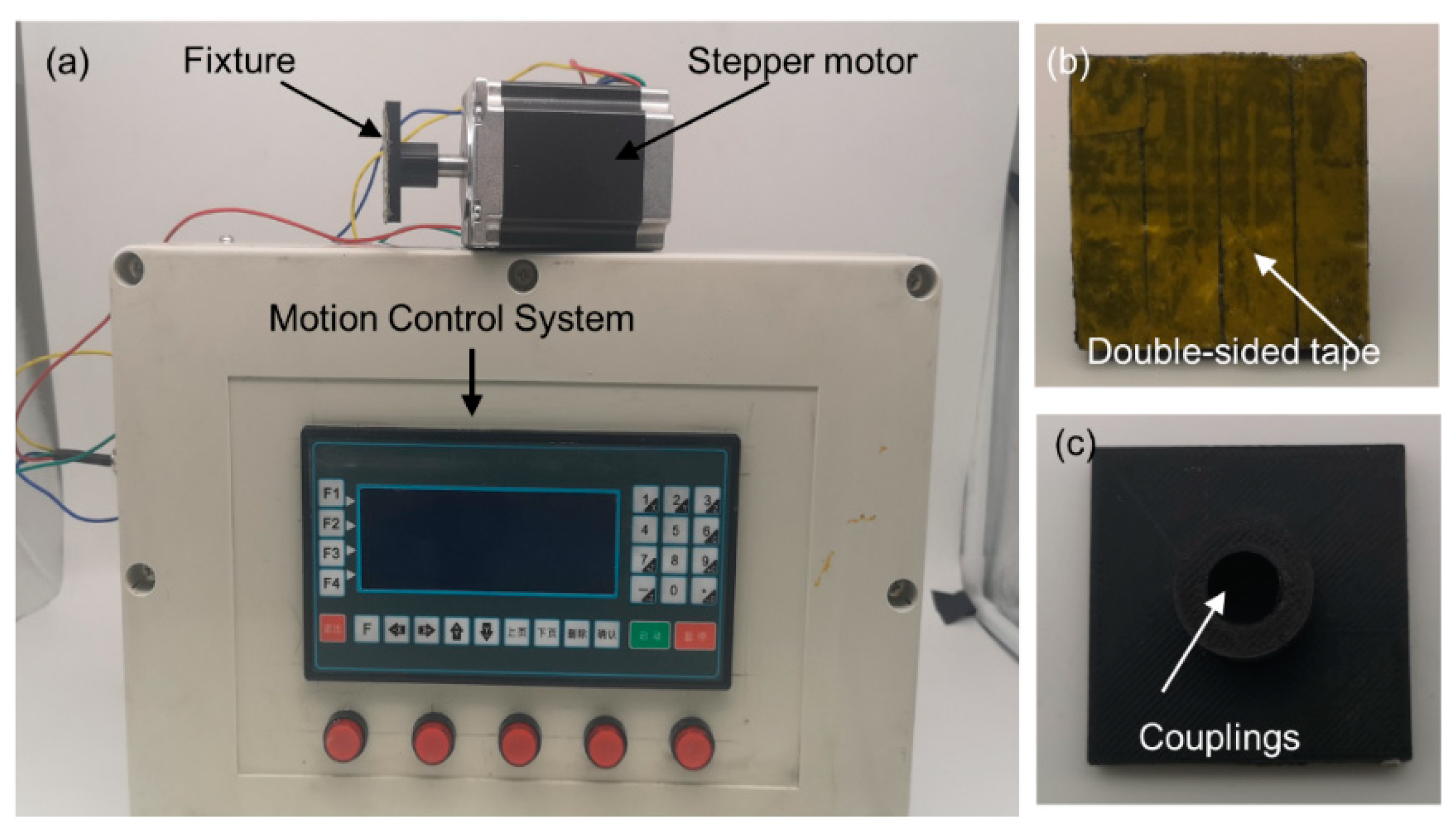
The designed antenna is expected to have different radiation characteristics when the patch plane is rotated at different angles. To realize that, the rotation angle of the antenna could be accurately controlled when measuring the reflection coefficients. In this work, a turntable is designed and manufactured, as shown in
Figure 6a which consists of a stepper motor, a motion control system, and a clamp.
The stepper motor is provided by Changlin Automation Technology Co., Ltd., Wuxi, China. The manufacturer model is 57BYGH801, and its rated voltage and current are 4 V and 2A, respectively, and the holding torque is 10,000 g·cm.
The motion control system is produced by Dopcon Automation Technology Co., Ltd., Beijing, China. The manufacturer model is TC55 and it is equipped with a 32-bit central processing unit (CPU), a servo motor, a liquid crystal display, and a contact keyboard. The movement state can be adjusted manually or using a computer. In manual fine-tuning mode the angular resolution is 0.2°, which meets the requirements for accurate angle control.
The clamp is used to fix the antenna and the stepping motor. The clamp can be quickly fabricated using the Fused Deposition Modeling (FDM) 3D printing method. The front and back views of the clamp are shown in
Figure 6b,c. The double-sided adhesive on the front of the clamp can be completely attached to the ground plane of the antenna, and the coupling at the back of the clamp connects the antenna with the stepping motor. Another clamp with two fins is also manufactured and used, as shown in
Figure S4.
6. Results and Discussion
6.1. Reflection Coefficient
We use a vector network analyzer (VNA) E5063A (Keysight Technologies, Inc., Santa Rosa, DE, United States) to measure the reflection coefficients of the fabricated antenna.
The turntable rotates the antenna from 0° to −10°, −20°, −30°...−90° in the counterclockwise direction (counterclockwise rotations are marked by “-”). Similarly, the turntable rotates the antenna from 0° to +10°, +20°, +30°... +90° in the clockwise direction (clockwise marked as “+”). The reconstruction process of the antenna at different rotation angles is demonstrated in
Movie S1.
A total of 19 sets of data for 19 angles (see
Table S2) are obtained in the measurements. To ensure that results are not redundant, seven sets of data (at −90°, −60°, −30°, 0°, +30°, +60°, +90°) are selected for analysis without affecting the accuracy. The impedance bandwidth and the center frequency under different rotation angles are also presented in
Table 2.
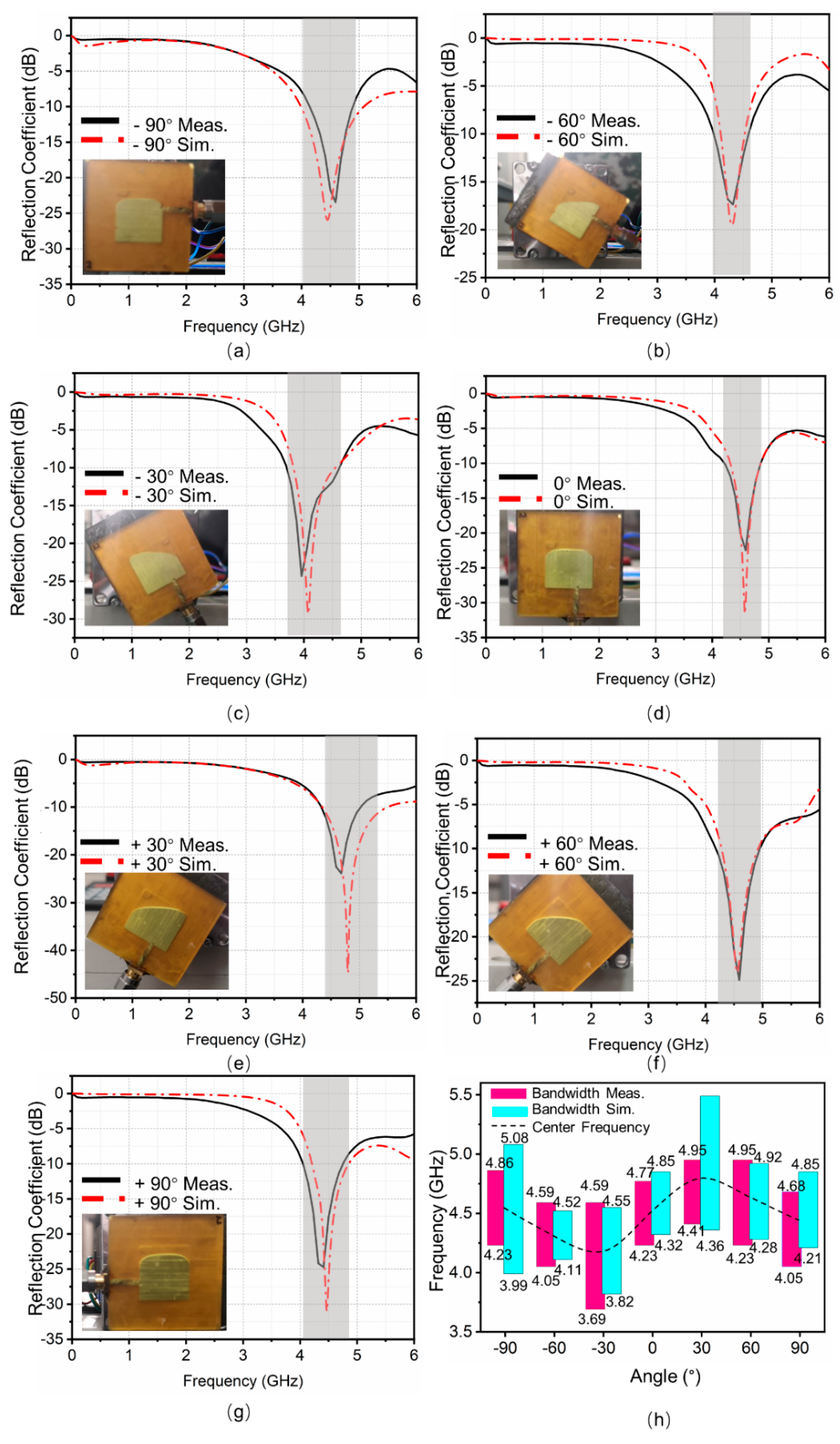
Figure 7a–g shows the reflection coefficients varied with frequencies at different rotation angles. At −60°, 0°, and +60°, the experimental results well agree with the simulation results. For other rotation angles, there exist some frequency deviations within the allowable error range.
There are many potential reasons for the errors. Firstly, there are several potential causes of manufacturing errors such as the size error of 3D printing and machining, as well as the volume error of the injected liquid metal. In addition, the interface between the liquid metal and NaOH solution in the fabricated antenna is a curved surface. Although the rounded corners are used to correct the model after being affected by the surface tension, there may exist some differences in the model. The main source of error is from manufacturing. Therefore, some high-precision instruments like flaw detectors can be used to scan 3D printed and machined parts to improve the quality of the antenna. In addition, EGaIn can be weighed and used more accurately. Finally, industrial instruments such as 3D scanners can be used to better reconstruct and optimize models.
The antenna is analyzed according to the rectangular patch. In the dominant mode of TM01, the current follows along the length of the patch to realize the frequency reconstruction. To summarize the law of frequency changes clearly, the impedance bandwidths of
Figure 7a–g are summarized in
Figure 7h. Firstly, the rotation angle is gradually changed clockwise from −90° to −30°, and the resonant frequency decreases. Subsequently, the rotation angle is gradually changed clockwise from −30° to +30°, and the resonant frequency increases. Finally, the rotation angle is gradually changed clockwise from +30° to +90°, and the resonant frequency decreases again. This periodic change is somewhat similar to a sine curve (see
Figure 7h). The entire working bandwidth (3.69–4.95 GHz) is measured following the same process.
6.2. Radiation Pattern
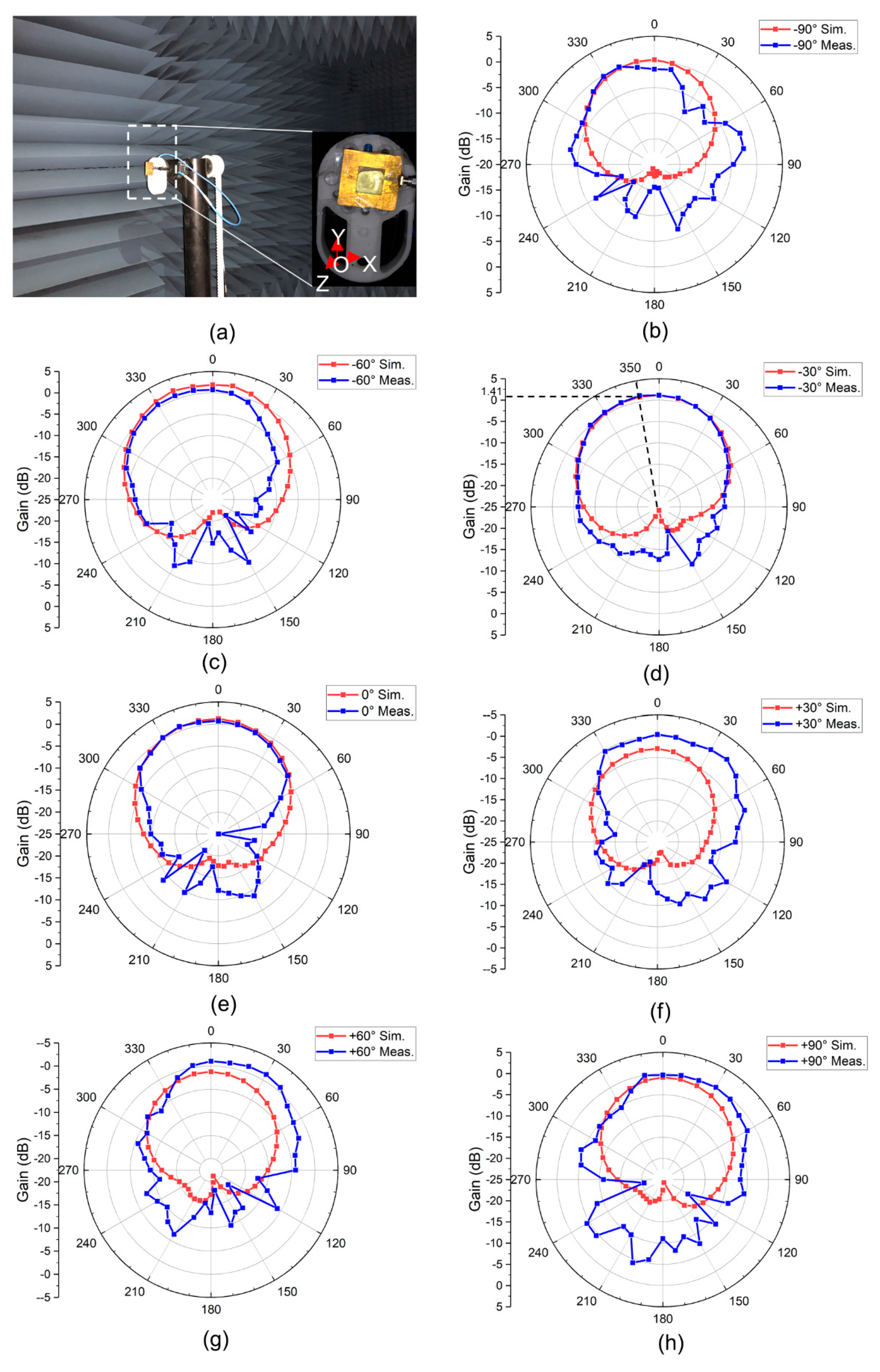
The antenna pattern is measured in a microwave anechoic chamber at the Tsinghua University. The measurement environment is shown in
Figure 8a. Note that the X-O-Y plane is the plane where the patch antenna is placed. The antenna is rotated around the
z-axis during the measurements. According to the reference frame defined above, the angle between the microstrip line and the reverse
y-axis is recorded as the rotation angle. Similarly, for the counterclockwise (clockwise) rotation, the rotation angle is recorded as a negative (positive) value. Therefore, the angle shown in
Figure 8a is −90°.
If the patch is placed horizontally (on the X-O-Z plane), the liquid metal would also be deformed in the horizontal plane, which will result in the inability to accurately measure the radiation pattern of the H-plane. Therefore, we only measure the radiation pattern of the antenna of the E-plane when the antenna is placed on the X-O-Y plane. For the same reason, the efficiency of the antenna cannot be measured.
The measurement and simulation results of the radiation pattern of the E plane are shown in
Figure 8b–h. The measured radiation pattern is consistent with that of a typical patch antenna, where the main lobe faces the
z-axis and the sidelobe level is lower, suggesting that the antenna has the end-fire characteristics.
The measurement results are also in agreement with the simulation. The measurements also show that for a rotation angle of −30°, the antenna achieves a maximum radiation gain of 1.43 dBi with the maximum radiation direction of 350°. Except for the manufacturing errors mentioned above, the error sources of the radiation pattern may also come from the measurement environment and measurement process, such as calibration errors and rotation angle errors.
6.3. Discussion
For comparison, several frequency reconfigurable antennas based on different principles are presented in
Table 3, which includes solid antennas [
2,
3,
4] and liquid antennas [
5,
6,
7,
8]. Compared with other works, the antenna in this paper provides a larger tunable range (3.69–4.95 GHz). This operating frequency range covers most of the n77 (3.3–4.2 GHz), n78 (3.3–3.8 GHz), and n79 (4.4–5.0 GHz) channels in the 5th generation (5G) mobile networks. Particularly, for rotation angles within a range of −30° to +30°, the resonant frequency of the antenna is monotonously changed with the rotation angles, which makes it be a promising candidate as a tilt sensor.
However, in many cases, the gain of the antenna is low, i.e., the antenna loss is relatively high. The loss is the collective impact of the liquid metal, NaOH solution, the
HT® 300, the microstrip feeder, and the manufacturing errors. Firstly, the liquid metal is sealed by the
HT® 300 resin, so the liquid metal patch antenna is covered by the dielectric layer that reduces the gain and efficiency of the antenna. One may consider reducing the thickness of the dielectric layer H3 and its dielectric constant
εr to further improve the antenna gain and its efficiency. Secondly, it is seen in [
24] that reducing the solubility of the alkaline solution improves the efficiency and gain of the antenna. In addition, the ground plane was fabricated using pasted copper foil. If the copper foil is not flat or becomes oxidized during the soldering process, the performance of the antenna would decrease. To address this issue, one can use copper deposition instead.
Although the structure of the rotating-driven liquid metal reconfigurable antenna designed in this paper is simple, as a proof-of-principle design, it provides a new method for the reconfigurable design of liquid metal antennas. The results presented in this paper can be further extended to many different antennas with reconfigurable frequency, pattern, and/or polarization through different patch shapes.


 ,
, 


