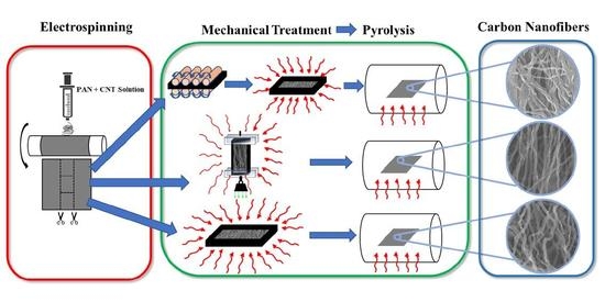
The synthesis route of pyrolytic carbon nanofibers is shown in
Figure 1. First, we prepared solutions of PAN precursors that are infused with carbon nanotubes [
4,
10]. Then, the carbon precursors solution is electrospun into polymer nanofibers mats in a process that is described in detail in our previous reports [
4,
10,
11,
12,
13]. The electrohydrodynamic forces inherent in the electrospinning process, combined with induced shear fields on the boundary layers of CNTs, unwind the polymer chains and carry out the first stage of molecular alignment in the synthesis process [
6,
7,
14]. Upon electrospinning, some of the polymer nanofiber mats are mechanically rolled and treated under approximately 5.88 MPa compressive stress, while another portion of polymer fibers are treated with a tensile load of 52 kPa. The mechanical stresses augment the alignment of the molecular chains and forge the scaffold of the final carbon structure by confining the polymer chains during the formative cross-linking process in stabilization [
1,
2,
3,
4,
10,
11,
12]. Both groups of fiber precursors were stabilized in air at 280 °C and then pyrolyzed under identical conditions at 1000 °C. After implementing fabrication and treatment processes, we analyze the tension-induced pyrolytic carbon nanofibers (TIPC) and compression-induced pyrolytic carbon nanofiber (CIPC) in a series of materials and mechanical characterizations.
3.1. Morphology Analysis of Stress-Induced Carbon Nanofibers
Scanning electron microscopy allows us to study the effects of different treatments on the final morphologies of pyrolytic carbon fibers (
Figure 2). While all three samples’ nanofibers demonstrate modest alignments in the direction of electrospinning, the tensile treatment of electrospun PAN has resulted in moderately more aligned carbon nanofibers compared to the untreated and compression-treated samples. Using the same micrographs, the average diameter of TIPC fibers measured to be around 241 nm, which is smaller than the average diameter of untreated pyrolytic carbon fibers, which was measured to be 267 nm (please see
Figure S1 in the supplementary information).
Conversely, the morphology of CIPC exhibits significant differences from the morphologies of untreated and TIPC samples. From
Figure 2c, it appears that the compression treatment of PAN nanofibers under geometric confinement and at 120 °C (which is higher than PAN glass transition temperature) has initiated the cross-linking between the individual electrospun fibers. This phenomenon is highlighted by the larger average diameter of CIPC fibers, measured to be 378 nm, which have a broader size distribution and appear to have “flattened” cross-sections. Accordingly, in some areas of the CIPC fabric, the fibers merged and formed a more continuous layer of carbon film (
Figure S2 in Supplementary Information), which is less porous (in terms of macropores) compared to TIPC and untreated carbon samples. The effects of these morphological changes on the mechanical properties of the pyrolytic carbon will be discussed further in the mechanical characterization section.
Another noteworthy aspect of the mechanical treatment is how it affects the thickness of the carbon nanofiber mats, and consequently their porosity. We measured the thickness of all three carbon samples, which was obtained by using ribbons from the same electrospun mat and subjecting them to different mechanical treatment. The thickness of untreated pyrolytic carbon, TIPC, and CIPC ribbons measured as 0.213 mm, 0.196 mm, and 0.036 mm, respectively. The thickness measurements indicate that compression treatment significantly reduces the porosity and creates a closer network of CIPC nanofibers. The SEM micrographs in
Figure 2c and
Figure S2 corroborate that CIPC has far fewer pores in its tight geometric confinement compared to TIPC and untreated samples. The morphological characteristics and the likelihood of the interaction among the adjacent nanofibers within the pyrolytic carbon framework is an additional factor that, along with graphitization level, contributes to the mechanical response of stress-induced carbon samples. We will discuss this aspect further in the
Section 3.5.
3.2. Structural Analysis of CIPC and TIPC by Raman Spectroscopy
We open our analysis with a standard Raman spectroscopy of pyrolytic carbons. Subsequent to a considerable number of theoretical and experimental studies dedicated to the Raman spectroscopy of carbon nanomaterials in the past few decades [
8,
15], this method has been established as a standard tool to gain swift, reliable insights into the structures and defects of carbon specimens. Herein, we used Raman to mainly evaluate the graphitic quality of our stress-activated carbons (
Figure 3a). The main metrics of interest for our analysis are the values associated with D and G Raman peaks. The intensity and shape of G peaks is associated with the stretching motion of in-plane c–c bonds with sp2 hybridization. Thus, it represents the graphitic building blocks and crystallinity. The D is a disorder-originated peak and is associated with defects and divergence from the graphitic carbon structure.
Figure 3a displays the Raman spectra of TIPC (1-a1) and CIPC (1-a2).
Our first comparison between Raman spectra gives a clear edge to CIPC in terms of graphitic quality. Here, while CIPC demonstrates
ID/
IG = 0.71, TIPC registers a value of 1.13 for this ratio. The Raman results of tension-treated carbon fibers are consistent with similar studies using similar fabrication procedures [
9,
16]. The inferior graphitic quality of TIPC fibers could be caused by the lower tension threshold of the carbon fibers, which leads to microtears and the disruption of PAN fibers prior to pyrolysis. The presence of partial microtears—inevitable due to the nature of applied loading—in PAN yarns would locally relieve a number of nanofibers from tension (as they are dangling within PAN yarn) and essentially render the mechanical alignment of their molecular chains ineffective. Then, the subsequent stabilization will result in cross-linking among randomly curled precursor chains, yielding amorphous carbon regions.
The comparison between the pick location of CIPC and TIPC does not display any particular pattern. This is expected, as the high-temperature, lengthy pyrolysis step removes the residual mechanical stresses in the final carbons. It should be noted that it is inherently more difficult to control the exertion of tensile forces and produce uniform nanofiber fabrics. A significant number of materials (particularly brittle ones) tend to have lower tolerance for tensile loading compared to compressive loading. This phenomenon, which is due to the presence of discontinuities and micro-flaws, makes the tensile treatment of carbon precursors more challenging, as any effort to align their molecular chains via tensile stresses is capped by their lower limit of tensile strength. A method used in the carbon fiber industry to address this issue is the application of hot drawing, where polymer fibers are woven into robust yarns and are collectively stretched. The robustness of yarn and the intertwined nature of fibers will distribute the tensile stress more uniformly and mitigate the number of microtears. However, the Raman spectroscopy results of the carbon fibers manufactured by this method remain very similar to those of TIPCS reported here, pointing to the inherently different effects of tension and compression treatment [
1,
9].
3.3. Chemical Composition Analysis of CIPC and TIPC
In the next part of our analysis, we investigate how the nature of mechanical loading applied to PAN precursors (compressive or tensile) can influence the chemical bonds and amount of heterogeneous atoms in the resulting pyrolytic carbon fibers. In a previous study, we reported that a sizable amount of graphitic and pyridinic nitrogen atoms is preserved in the stress-activated carbons. We attributed the presence of these atoms to the low temperature of our pyrolysis step, typically carried out at 900–1000 °C, which is far lower than current industry standards (typically 1500–3000 °C). This is advantageous from different aspects; first, fabricating graphitic carbon at a lower pyrolysis temperature is remarkably more cost-effective; second, the presence of functional heterogeneities (such as pyridinic nitrogen) will positively contribute to the electrochemical performance of carbon nanofibers [
12,
17,
18,
19].
To compare the chemical composition of TIPC and CIPC, we performed X-ray Photoelectron Spectroscopy (XPS) and curve fitted the collected spectra to deconvolute the nitrogen peak, N 1s (
Figure 3b–d). The comparison of the XPS data drawn from both carbon types reveals that the total amount of the nitrogen—the main heterogeneous atom in pyrolytic carbon—maintains a similar fraction of approximately 4.7% in both carbons. However, the type of nitrogen exhibits an interesting variation from compression to tension. While CIPC demonstrates high contents of graphitic nitrogen (49.63%) and a small amount of pyrrolic nitrogen (10.24%), TIPC contains noticeably lower graphitic nitrogen (38.77%) and higher pyrrolic nitrogen (12.94%) concentrations. The fraction of pyridinic nitrogen remains similar (22.29% for CIPC and 22.03% for TIPC) in both carbons. TIPC also possesses a higher percentage of oxidized nitrogen (23.88% and 2.39%). The observations drawn from XPS analysis will be specifically meaningful in the context of carbon MEMS and microelectrodes, as graphitic and pyridinic nitrogen are reported to contribute positively to carbon’s electrochemical performance [
10,
11,
20,
21].
Overall, both carbon fibers show a similar breakdown of total carbon, nitrogen, and oxygen (
Figure 3c—top table). However, they exhibit a noticeable disparity in the amounts of graphitic, pyridinic, and pyrrolic nitrogen atoms embedded in their structures.
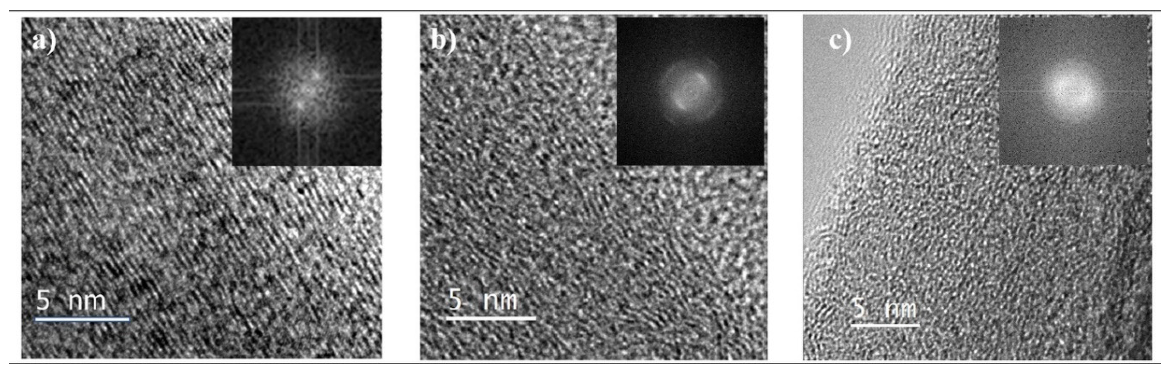
3.4. Transmission Electron Microscopy and Microstructure
To compare the microstructure of CIPC and TIPC, we employed transmission electron microscopy (TEM) imaging. While limited in its field of view, this high-resolution visual technique can offer nano-scale insights into the microstructure of the two carbons.
Figure 4 shows the high-resolution TEM images of CIPC (
Figure 4a) and TIPC (
Figure 4b).
Figure 4c is obtained from PAN/CNT-based pyrolytic carbon synthesized without mechanical treatment, but otherwise under the same synthesis parameters as CIPC (
Figure 4a) and TIPC (
Figure 4b).
Figure 4c provides us with a ground for comparison to see the general impact of mechanical activation (compressive and tensile) on the pyrolytic carbon microstructure.
Overall, both mechanically activated carbons (
Figure 4a,b) show an enhanced level of alignment of carbon planes in comparison with mechanically untreated carbon and amorphous carbon microstructures [
4]. Although both stress-induced carbons show similar microstructures, the CIPC carbon fringes appear to be slightly more aligned than those of TIPC. Moreover, the TIPC structure appears to be coarser with more broken carbon fringes, more undulations, and less ordering. This is consistent with the results of RAMAN spectroscopy analysis, which indicates a higher graphitization degree in CIPC fibers. On the other hand, the untreated sample (
Figure 4c) exhibits a disordered and haphazardly curled microstructure, which is in keeping with the accepted classification of PAN as a non-graphitizable polymer. Furthermore, the Fast Fourier Transform (FFT) of the
Figure 4c micrograph reveals symmetric rings, which is indicative of an amorphous carbon microstructure.
The carbon fringe separation distance (d spacing), derived from processing of the TEM images, corroborates the visual observation of microstructures of the two mechanically induced carbons. Here, TIPC shows an average d spacing of 3.65 Å, while CIPC’s fringe separation is 3.55 Å. The difference implies a closer stacking among CIPC carbon planes, which can be attributed to the nature of compression treatment of carbon precursors. As a reference, the d spacing for most of the carbon nanotubes and highly organized pyrolytic graphite is usually under 3.4 Å [
4,
22,
23]. An interesting element of the microstructure in carbon fibers is the trade-off between ordered graphitic structures and the amount of carbon edge planes. While the quantity of carbon edges is a main contributor to carbon MEMS/electrode’s performance, too much fragmentation of the carbon lattice could disrupt the graphitic network necessary for efficient electron mobility in carbon electrodes.
3.5. Mechanical Characterization of CIPC and TIPC
One of the most tangible synthesis–structure–property relationships in carbon can be studied by mechanical characterization of pyrolytic carbons manufactured through different routes. Mechanical characterization can be done on different scales, ranging from nano-scale/single fiber testing to macro-scale evaluation of carbon fiber mats [
2,
16,
24,
25]. For this study, we decided to obtain the mechanical properties of the stress-induced carbons in their as-pyrolyzed mat format. Assessing the collective properties of carbon nanofibers in functional geometries, such as carbon mats incorporated in electrodes, allows us to predict the mechanical behavior of these materials when used in sensing and storage devices [
26,
27,
28,
29]. While focusing on a single nanofiber has certain scientific advantages, the mechanical properties obtained from a single fiber analysis cannot be easily translated to larger, functional dimensions. Conversely, measuring the mechanical behavior of carbon fabrics in device-relevant dimensions is directly applicable. It is also important to note that the results of mechanical characterization of the larger carbon films may not be directly compared to single fiber characterization due to additional factors in bulk dimensions, such as the porosity of the fiber mat, nanofiber dispersity, and fibers’ orientations. [
16,
24,
25].
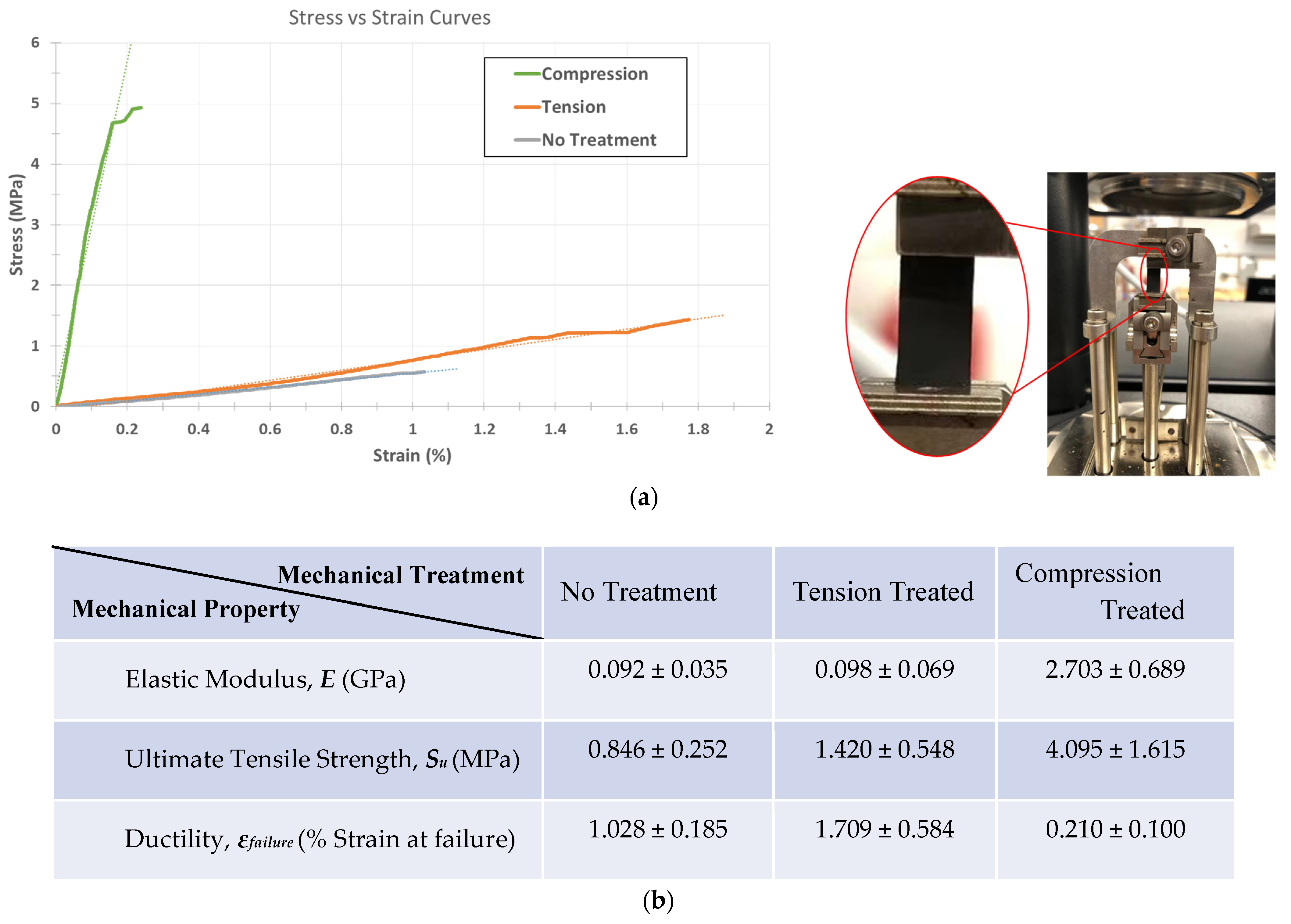
Dynamic Mechanical Analysis (DMA) allowed us to accurately characterize the mechanical behavior of the delicate carbon mats. The main objective of mechanical characterization for this study is to obtain reliable stress–strain curves for the samples. As the focus is to assess the behavior of carbon samples for device integration, we used the engineering definition of stress , where A is the initial cross-sectional area of the strip and F is the forces applied on the carbon fabric strips. Using a tensile film clamp, the standard stress and strain tests were conducted using a controlled force ramping rate at 1 N/min until the samples yielded from the center.
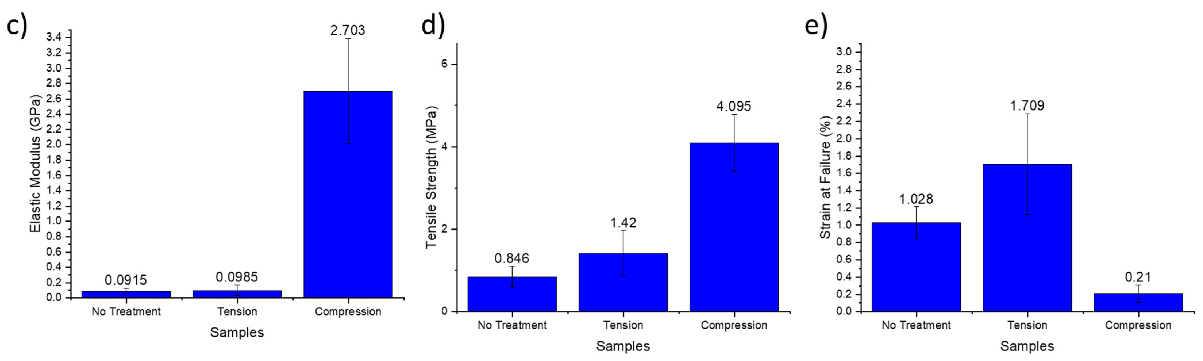
First, we focus on the elastic response of each sample as the most important aspect of mechanical behaviors. As shown in
Figure 5, the compression-induced pyrolyzed carbon demonstrates a remarkable increase in elastic modulus (
ECIPC = 2.703 GPa) with a 29-fold rise over the Young’s modulus of the control untreated pyrolytic carbon (
Euntreated = 92 MPa).
Tension treatment also slightly enhances the stiffness of carbon fiber to
ETIPC = 98 MPa, a 6.5% increase, which is far less than the effect of compression treatment. It is important to note that the over-tensioning of carbon precursors in our experiments often results in compromised/partially torn carbon fiber mats, where the defects are not visually detectable without microscopy. In these cases, over-tensioned carbons will be even weaker than untreated pyrolytic carbons due to the structural damages. Therefore, it is necessary to modulate the tension treatment to an acceptable limit to see its strengthening effect. The elastic behavior results obtained in the current study agree with the previously reported correlation between carbon’s stiffness and its graphitic quality [
30,
31,
32]. Another parallel between carbons’ composition–microstructure and mechanical behavior is the higher concentration of graphitic C–N bonds in CIPC compared to TIPC, which is a likely contributor to a more graphitic microstructure, and consequently, higher stiffness in compression-induced carbon fibers [
30,
31,
32].
Another notable observation is the change in ductility of the carbon fiber fabrics upon mechanical treatment. Using strain at failure as a measure of ductility, DMA shows that while compression treatment drastically boosts the elastic response of pyrolytic carbon, it lowers its strain at failure to
ϵf = 0.21%, denoting a significant drop in carbon mats’ ductility. Interestingly, this pattern is not observed in the tension-treated carbon mats, as they exhibit an enhanced ductility with (
ϵf = 1.71%) compared to that of the control, untreated mat with (
ϵf = 1.03%). The observed ductility trend is mostly for thin film carbon fabrics used as electrodes for sensing and electrochemical application; if the pyrolytic mats are woven into carbon yarns, the result may vary [
30,
31,
32,
33,
34,
35,
36].
The ultimate strength, S
U, of carbon fabrics is another mechanical property that is crucial to carbon device integration. In many applications, the carbon nanofiber fabrics should withstand different loading scenarios while functioning as electrodes and sensing probes. This mechanical tolerance for loads is usually constrained by the sample’s ultimate strength (
Figure 5). Both CIPC and TIPC show a promising enhancement in their ultimate strength, with TIPC registering 68% enhancement (
SU,TIPC = 1.420 MPa) and CIPC demonstrating a 484% increase (
SU,TIPC = 4.095 MPa) in their ultimate strength values. Combined with their elastic behavior, the mechanical characterization suggests that compression treatment enhances the stiffness and strength of pyrolytic carbon mats notably more than tension treatment at the cost of making them more brittle.
It is beneficial to explore the effects of the morphologies of different carbon nanofibers on their mechanical properties. From the SEM micrographs, tensile treatment—performed along the electrospinning direction—has enhanced the alignment of carbon nanofibers in TIPC mats. This augmented alignment is likely another factor that contributes to the increase in TIPC’s elasticity and strength, which are measured along the electrospinning/treatment direction. Conversely, in the case of CIPC mats, the compression treatment of spun fibers has visibly resulted in the inter-fiber cross-linking and formation of semi-continuous carbon layers during the pyrolysis (
Figure S2). The enhanced continuity and inter-connection of nanofibers results in a more rigid 2D, less porous carbon framework, which exhibits a significant surge in stiffness and strength. However, such continuity can lead to reduced ductility in CIPC, as a small tear in the carbon film can propagate and result in failure at smaller strains compared to more porous TIPC and untreated mats.
The mechanical, structural, and morphological characterizations in the current study suggest that the morphology and alignment of carbon nanofibers, along with their graphitization level (an established factor on the mechanical properties of carbon) are among the main contributors to the mechanical properties of stress-induced pyrolytic carbons. While this report provides useful insights on the mechanical behavior of carbon nanofibers, the influence of fiber alignment and testing direction on the mechanical response of carbon fibers requires further investigation, which the authors plan to pursue in a future study.
The mechanical behavior has numerous characteristics, including but not limited to fracture toughness, rigidity, resilience, etc. The complete mechanical characterization of the carbon fibers merits a dedicated study that explores the dimension of the pyrolytic carbon samples (such as micro-/single fiber, meso-, and macro-scale) as well as the scale of characterization and the effects of nanofibers’ orientation and alignment. The current study provided an overview of the methodology and main mechanical characteristics of mechanically induced pyrolytic carbons in the geometries relevant to devices integration. This report will be followed up with further studies of the mechanics of stress-induced pyrolytic carbons in our future works.


