Abstract
The flow channel design of bipolar plates plays a significant role in the proton exchange membrane fuel cells operation, particularly in thermal and water management. The pursuit of low-pressure drop supply and flow field uniformity in PEM fuel cells has not stopped, resulting in numerous new bipolar plate flow channel designs. The biomimetic leaf vein shape-based flow channel and lung flow channel designs can significantly improve gas supply uniformity and reduce pressure drop. Therefore, we propose a snowflake-shaped bionic channel design by integrating the advantages of the leaf vein shape and lung shape channel. A 3D multi-physics fuel cell model is used to verify the feasibility and superiority of the bionic snowflake design in improving fuel cell performance, especially in reducing the pumping work. The local pressure distribution, oxygen distribution, water distribution, and current density distribution are used to reveal the enhancement mechanism of the new snowflake flow channel. The flow uniformity is further enhanced by using multi-objective (13 target parameters) and multi-parameter (18 independent variables) genetic algorithm optimization. The general goal of this work is to provide a new strategy for the thermal and water management of PEM fuel cells.
1. Introduction
Proton exchange membrane (PEM) fuel cells are electrochemical devices that convert hydrogen energy into electricity [1,2]. PEM fuel cells have become a promising substitute for fossil-fueled technologies because of their high efficiency, low operating temperature, fast start-up, low noise, and low emissions [3,4]. With such advantages, PEM cells have great potential applications in the automotive industry, small stationary power generation systems, or distributed energy systems [5,6].
The bipolar plates play significant roles in the PEM fuel cells, such as distributing fuel and oxidant, collecting and transporting current, removing product gas and liquid water, and providing structural rigidity for the cell stack assembly. Hence, the bipolar plate design has a significant impact on the performance of the fuel cell, which has been studied extensively [3,4]. The commonly used microchannel styles include parallel straight channel, serpentine, cross-finger [5], dotted [6], and so forth. These channel styles are simple and easy to fabricate, but there is still much room for improvement and optimization in the aspects of reactant uniformity, pressure drop, and water removal [7,8]. To deal with such issues, various channel designs have been proposed, such as fractal channels [9], composite flow channels [10], spiral flow channels [11], radial flow channels [12,13], and optimized pin-type flow channels [14]. These novel types of flow channels aim to make the reactants uniformly distributed inside the cell and facilitate water removal, thus improving the overall performance of the fuel cell.
In addition to these novel flow channels, a series of bionic structural flow channel designs inspired by nature are also proposed, such as leaf veins [15,16,17,18,19,20], lung tubes [21,22,23,24], and lymphatic topology [25]. These novel bionic designs aim to solve the issues of flow field uniformity [16], gas diffusion and liquid water removal [17], and system pressure drop [21]. Table 1 compares current flow channel designs in PEMFCs. In summary, the general principles of the flow channel design are to address the following issues: (1) according to Murray’s law, the size of the channel should be proportional to its volumetric flow requirements; (2) when using a branching structure, the branching angle should be less than 90-degree bends to avoid stagnation zones and the short cut of flows; (3) the flow field design should take the reactant consumption along the flow channel into account; (4) the appropriate proportion of the flow channel area and rib area in order to provide sufficient oxygen and effective conductivity of the electrode plate over the cathode reaction zone; (5) subcostal convection can facilitate the oxygen transport in gas diffusion layer; and (6) provide effective liquid water removal inside the cathode to prevent clogging.

Table 1.
Summary of flow channel design for PEM fuel cells.
According to these principles, neither a single leaf vein design nor a single lung tube design will suffice. For example, the lung design is favorable for the small pressure drop, while the leaf vein branching design is better for the flow uniformity. However, both pressure drop and uniformity are favorable for the flow channel design of fuel cells. Therefore, we introduce a new flow channel design inspired by nature’s snowflake, which considers both the lung fractal and leaf vein branching bionic structures. Compared with the traditional flow channel designs, the new flow channel design can achieve better gas diffusion and liquid water removal performance with lower pressure drops. Fuel gas mass transport, microchannel liquid water management, overall pressure drop, and fuel cell performance are examined by a 3D multiscale and multi-physical model. The flow channels are further optimized by a multi-objective optimization method based on a genetic algorithm. The general goal of this work is to provide a new strategy for the thermal and water management of PEM fuel cells.
2. Numerical Model
2.1. Geometric Model
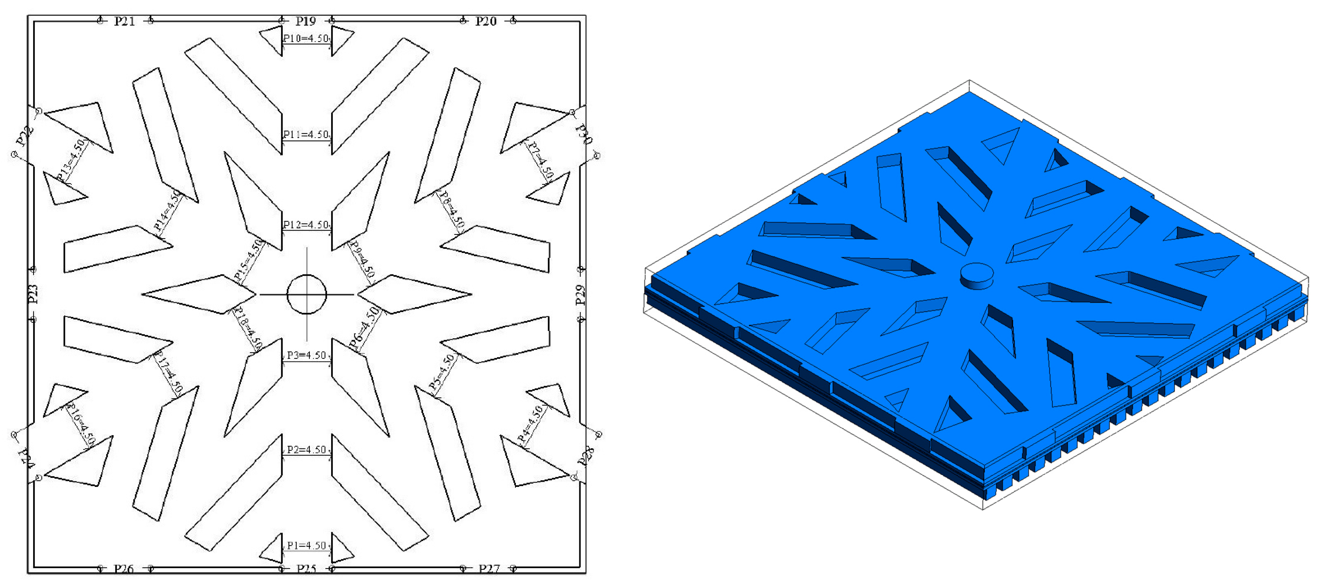
A PEM fuel cell model with a 3D sandwich structure is built in this work, which has been widely used to study mass transport and energy conversion numerically. The PEM fuel cell comprises five parts: bipolar plates, flow channels, gas diffusion layer, catalytic layer, and proton exchange membrane. Since the cathode flow channel is more significant for the PEM fuel cell than the anode, we only induce the snowflake design for the cathode flow channel. The details of the design geometry are shown in Figure 1. The width of the six main channels, branch, surrounding channel, and outlet of the snowflake bionic flow channel are 4.5 mm, 3.5 mm, 0.75 mm, and 0.5 mm. The circular inlet is located in the center of the bipolar plate with a diameter of 3.5 mm. The total area is 25 cm−2, with a channel area ratio of 58.29%. The thicknesses of the proton exchange membrane, catalyst layer, gas diffusion layer, and collector plate are 0.15 mm, 0.01 mm, 0.35 mm, and 2.5 mm, respectively. The height of the anode and cathode channel is 1.5 mm.
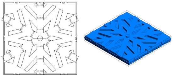
Figure 1.
Snowflake bionic flow channel design.
2.2. Governing Equations
Different positions in the fuel cell correspond to different governing equations, which are divided into two parts: fluid flow and electrochemical reaction. Three-dimensional, single-phase, isothermal PEM models include momentum equations, continuity equations, conservation equations, water content equations, and potential equations. The following assumptions are induced to build the multi-physical model. The fluid is non-Newtonian, incompressible, flowing micro-laminar flow, and constant physical properties. The porous layers are all isotropic.
The continuity equation is solved by
The momentum equation is solved by
The source term is the resistance source term of the porous structure
The component equation is solved by
The source term is solved by
The property, such as two-phase density, is calculated by,
The transfer equation of product water in the flow channel, gas diffusion layer, and catalytic layer is calculated by,
The product water transfer equation in the membrane is calculated by
The electrochemical reaction proceeds in the catalytic layer and the reaction equation is
The current collector and membrane potentials are calculated as:
The source term is solved by
Assuming that the anode potential is equal to the ground potential,
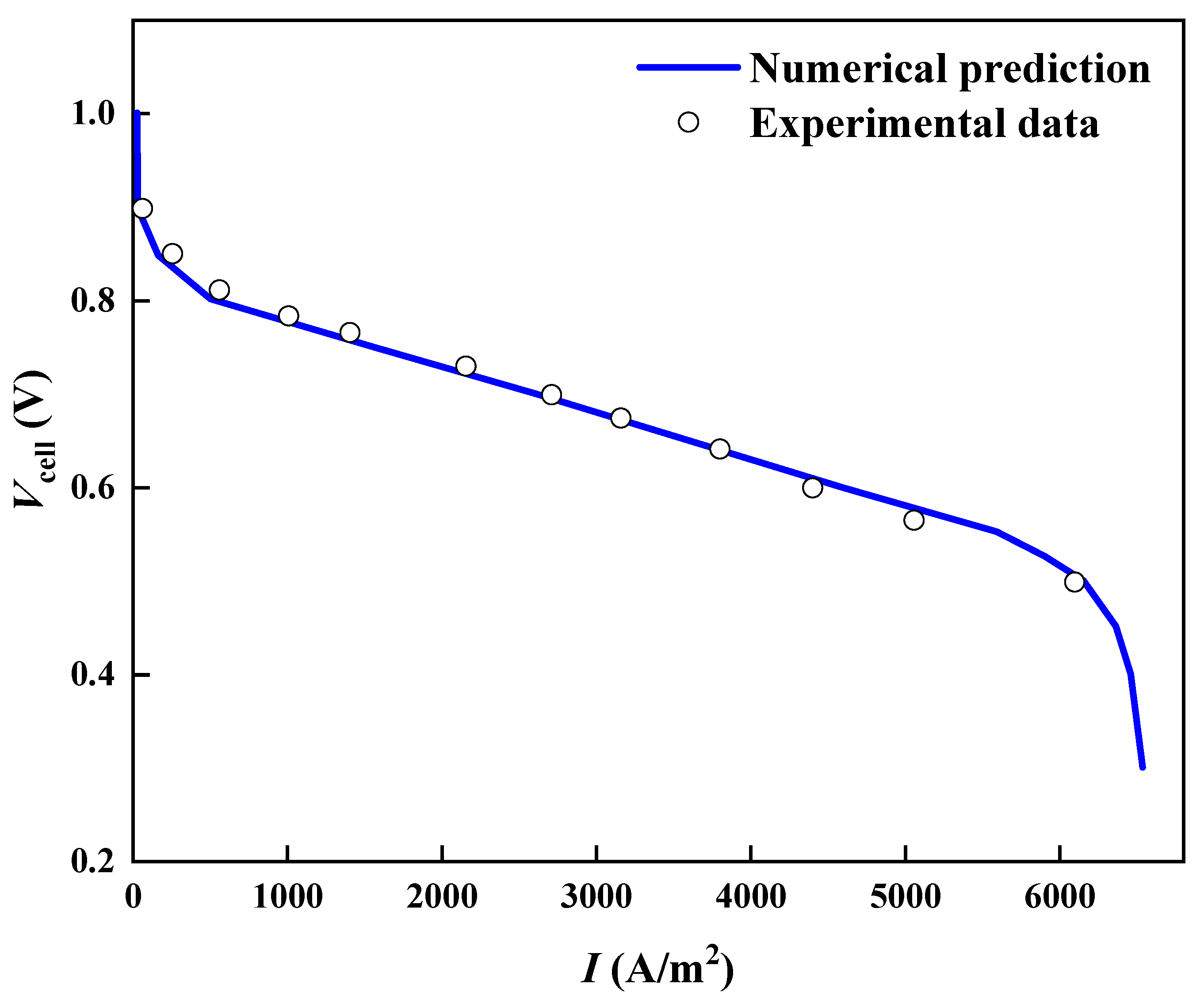
The initial temperature of the PEMFC for this study is 353 K. The anode inlet fuel is 20% H2O, 80% H2, which has a mass flow rate of 2.7 × 10⁻⁷ kg s−1. The cathode inlet is 10% H2O, 20% O2, and 70% N2, with a mass flow rate of 7.5 × 10.6 kg s−1. The physical property parameters are shown in Table 2. The model validation is shown in Figure 2, which shows a good agreement between the experiments and the present multi-physical model.
Table 2.
Fuel cell parameters.

Figure 2.
Model validation.
3. Results and Discussion
3.1. Feasibility and Advantage of Snowflake Bionic Flow Channel
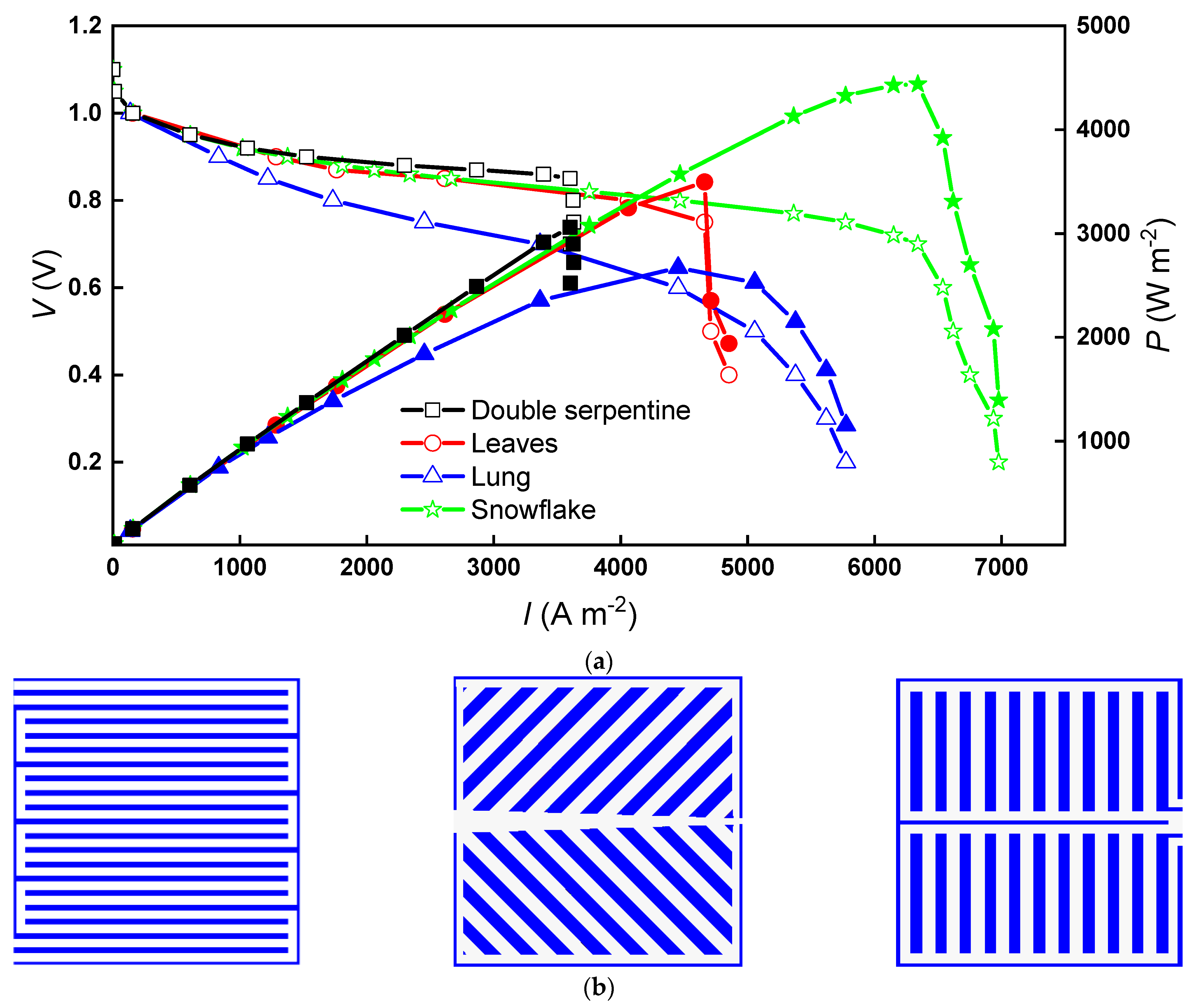
Figure 3 shows the polarization curve and the power density curve for the snowflake bionic flow channel with three classical flow channels, dual serpentine (DS), leaf (LE), and lung (LU). At high potentials, the difference in cell current density between the leaf-shaped flow channel, snowflake flow channel, and double-snake flow channel designs is small, but all three flows are higher than the lung-shaped flow channel. When the potential is between 0.92 V and 0.82 V, the current density of the PEM fuel cell with the dual serpentine flow channel is slightly higher than that of the lung flow channel and the snowflake flow channel, with a maximum difference of 1060 A m−2. This region is in the ohmic polarization region, in which the main reason affecting the current output is the need to overcome the resistance of electron conduction through the electrode material and various connecting components and the ion conduction through the electrolyte. Therefore, the resistance of the leaf-shaped flow channel, lung-shaped flow channel, and snowflake flow channel cells are all greater than that of the dual serpentine flow field cell.
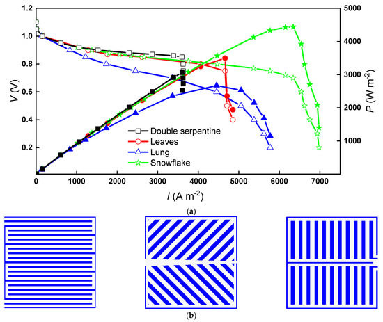
Figure 3.
The polarization curve and power density curve of PEM fuel cells with various designs: (a) U-I curve; (b) dual serpentine, leaf, and lung designs.
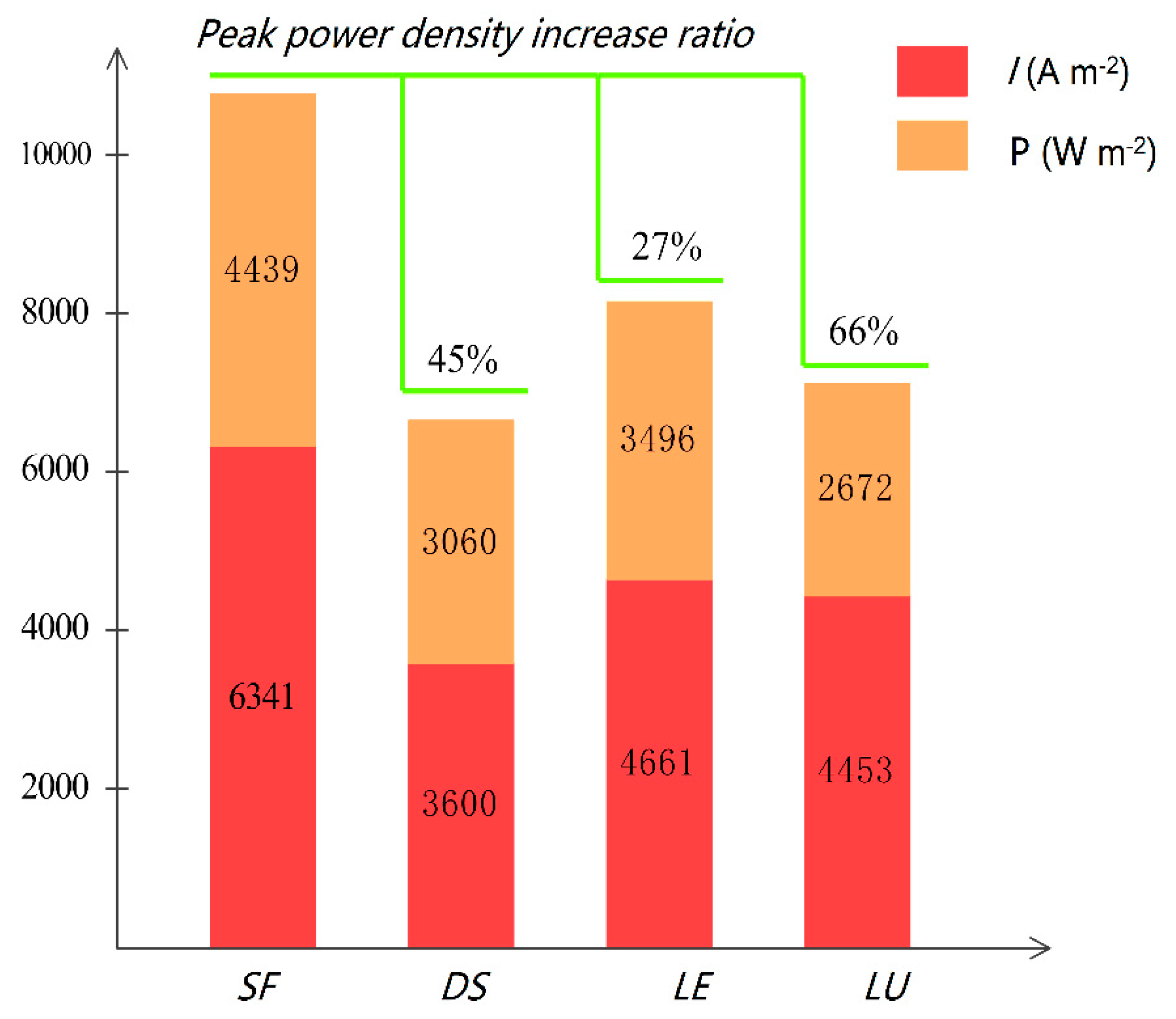
As the potential decreases, the current density in the dual serpentine flow channel hardly changes and enters the concentration polarization region early. The current of the PEM fuel cell with the leaf-shaped flow channel, lung-shaped flow channel, and snowflake flow channel will continue to increase. The current density corresponding to the occurrence of concentration polarization in the snowflake channel is 1.7 times higher than that in the dual serpentine channel fuel cell, 1.3 times higher than that in the leaf-shaped, and 1.4 times higher than that in the lung-shaped channel fuel cell. When the leaf flow channel, snowflake flow channel, and dual serpentine flow channel enter into the concentration difference polarization zone, the current density of the lung-shaped flow channel still increases with the decrease of potential. The overall polarization curve is relatively flat. The unique concentration polarization characteristics of the lung-shaped flow channel are closely related to its water management, which will be discussed in detail below. The concentration of reactant gases in the concentration polarization zone is heavily depleted, resulting in a low concentration of reactants on the electrode surface. Due to mass transfer limitations, sufficient reactants cannot be supplied to the electrode surface, resulting in voltage loss. Therefore, it can be expected that the snowflake flow channel has better mass transfer performance in the reaction interface. Figure 4 shows the peak power density values for the various flow channels. A maximum of 66% increases the snowflake-shaped flow channel’s peak power density compared to the other three flow channels.
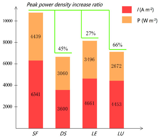
Figure 4.
Peak power density of PEM fuel cells with various flow channels.
The performance-enhancing mechanism of the snowflake flow channel can be explored by the local transfer characteristics of cathode pressure drop, oxygen mass fraction, water content and current density in the membrane.
3.2. Local Distribution and Transport Characteristics for the Snowflake Flow Channel
The overall pressure drop in the fuel cell flow channel is critical for evaluating fuel cell performance, which is relevant to the pump power to feed the fuel and oxidant to the fuel cell [30,31]. More minor pressure loss indicates a higher cost-benefit for cell power generation. In contrast, a large pressure drop can force more fluid fuel or oxidant to penetrate the diffusion layer to the catalytic layer for reaction. At the same time, it will enhance the forced convection of liquid water and facilitate the removal of product water. Therefore, finding an optimal pressure drop value is significant to improving the fuel cell performance.
Table 3 compares the pressure drop of the four flow channels inside the cathode bipolar plate. Pressure drop is calculated as the area-weighted average pressure at the inlet minus the area-weighted average pressure at the outlet. The snowflake-shaped flow channel designed in this paper has a vertical inflow in the middle and outflow all around. Hence, the overall pressure drop is tiny, with an average pressure drop of only about 1.1 Pa under ideal conditions. The average pressure drop in the double serpentine flow channel is 56.40 Pa, the average pressure drop in the leaf-shaped flow channel is 8.48 Pa, and the average pressure drop in the lung-shaped flow channel is 7.92 Pa. As the reaction gas is gradually consumed from the inlet to the outlet, the local pressure in the flow channel gradually decreases from the inlet to the outlet. The slightest pressure drop in the snowflake-shaped flow channel makes the reactant gas diffuse thoroughly and uniformly throughout the flow channel, increases the concentration of reactants on the catalytic layer surface, and delays the concentration polarization of the whole cell. The slight pressure drop allows the snowflake flow channel to not cause local fuel supply shortage due to a too fast local reaction, which significantly affects the cell performance.
Table 3.
The pressure drops for the PEM fuel cells.
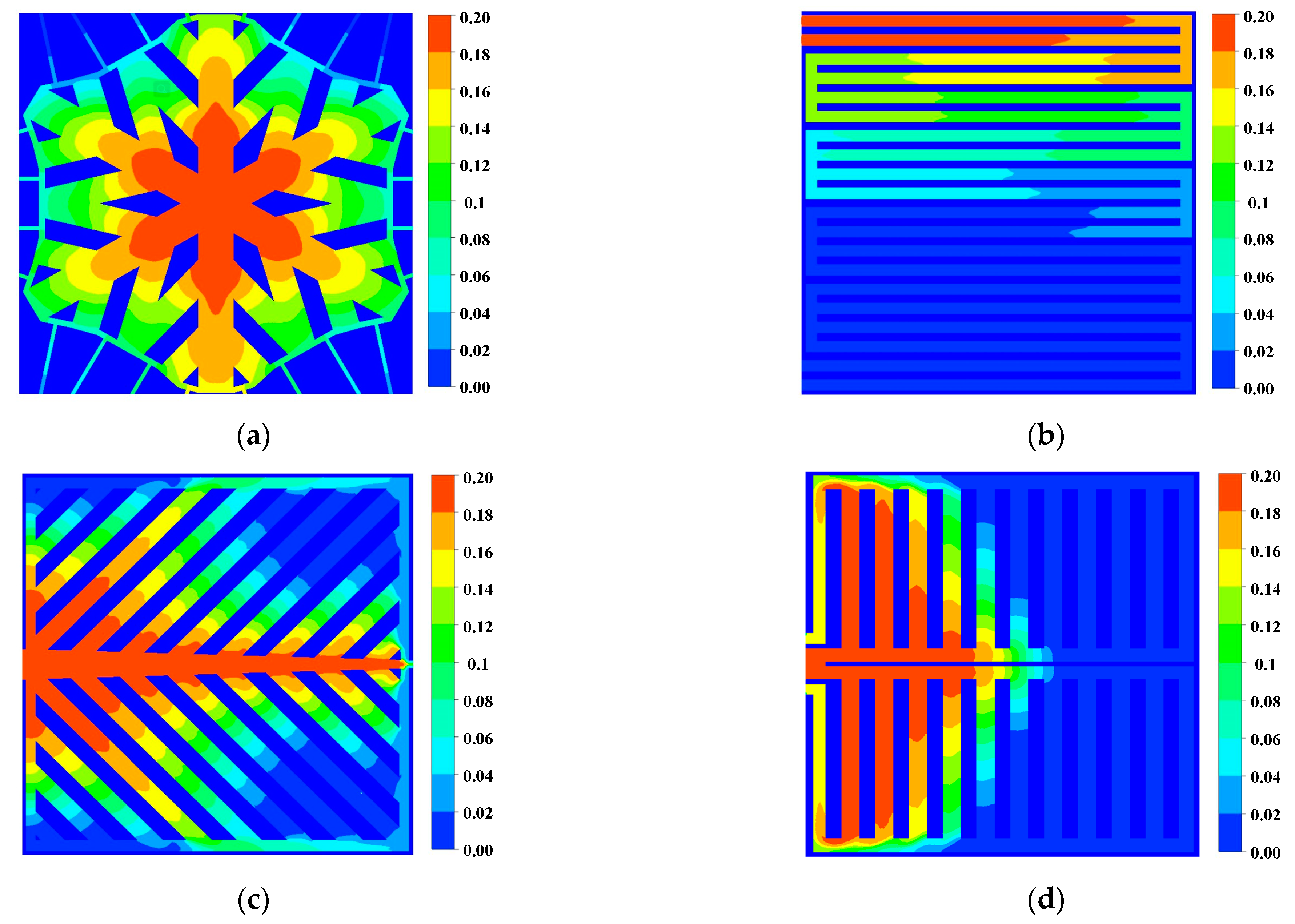
The oxygen content directly affects the electrochemical reaction rate of the PEM fuel cell. As shown in Figure 5, the oxygen mass fraction in the second half of the snowflake flow channel is reduced to 0.06. The local mass fractions in the other three channels are almost 0, indicating that the cell experiences a local gas supply deficiency, which affects the overall cell performance. In addition, the distribution of oxygen in the flow channel region of the snowflake flow channel is more uniform than that of the other flow channels. Comparing the area of the high concentration region in Figure 6 with Figure 5, it can be found that the oxygen content in the diffusion layer will be slightly lower than that in the channel. With sufficient oxygen supply in the snowflake flow channel, the leaf-shaped flow channel, and the lung-shaped flow channel, there is no fuel outflow at the exit of the dual serpentine flow channel and the oxygen supply is insufficient. Therefore, the fuel utilization rate of snowflake, leaf, and lung channels is lower than that of double serpentine channels. The lack of local fuel supply in the leaf-shaped and lung-shaped channels is mainly due to poor water management. The snowflake channel is mainly due to low channel resistance and rapid oxygen flow through the cell channel. Thus, the channel topology should be further optimized, which will be discussed in the following section.

Figure 5.
Oxygen mass fraction in the flow channel (0.8 V): (a) Snowflake bionic flow channel; (b) dual serpentine flow channel; (c) leaf-shape bionic flow channel; (d) lung-shape bionic flow channel.
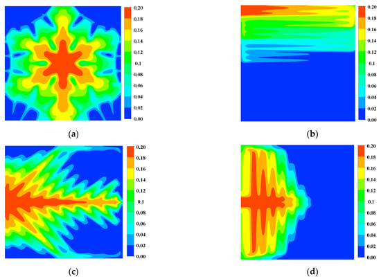
Figure 6.
Oxygen mass fraction of cathode gas diffusion layer (0.8 V): (a) Snowflake bionic flow channel; (b) dual serpentine flow channel; (c) leaf-shape bionic flow channel; (d) lung-shape bionic flow channel.
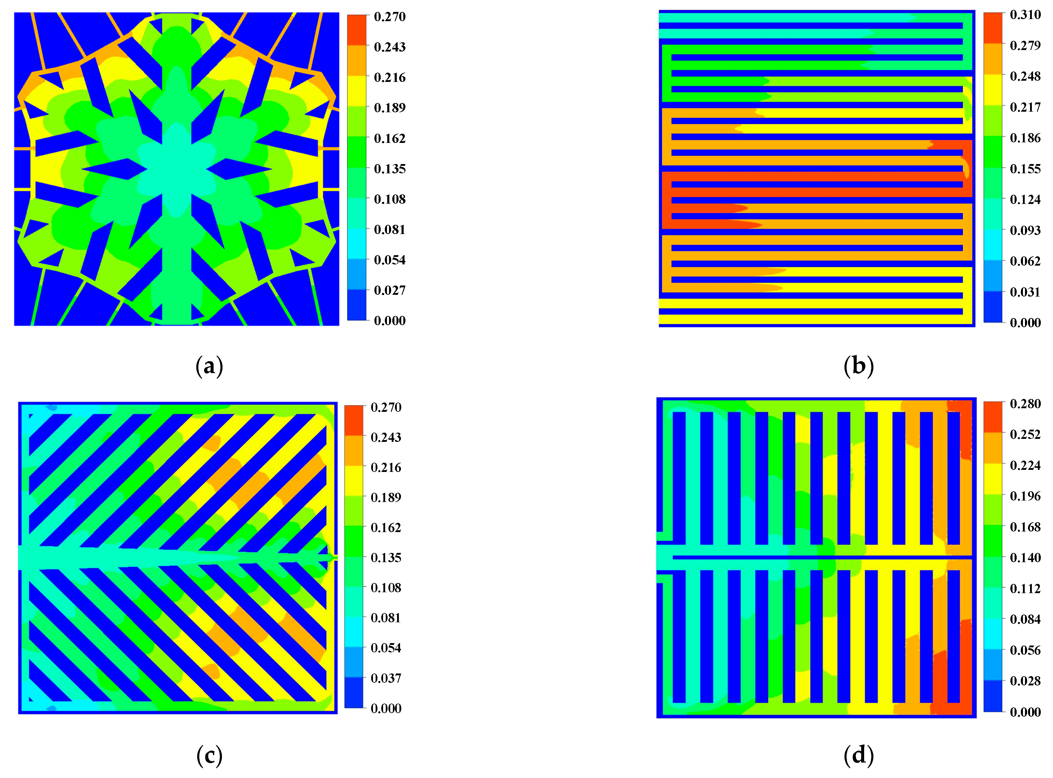
Figure 7 and Figure 8 show water distribution within the flow channel and diffusion layer. In the middle region of the dual serpentine flow channel, the liquid water content, the maximum is 31% and the leaf-shaped and lung-shaped flow channels have the most liquid water at 27% and 28% downstream of the flow channel. In the snowflake flow channel, the liquid water concentration is near the outlet, which has much less effect on the electrochemical reaction than the double serpentine flow channel, the leaf-shaped flow channel, and the lung-shaped flow channel. In addition, the maximum value of water content in the snowflake channel is also lower than that in the dual serpentine channel and the lung-type flow channel. The distribution of liquid water within the diffusion layer was similar. Therefore, the water management of the snowflake flow channel bionic structure flow channel is better than other comparison flow channels.
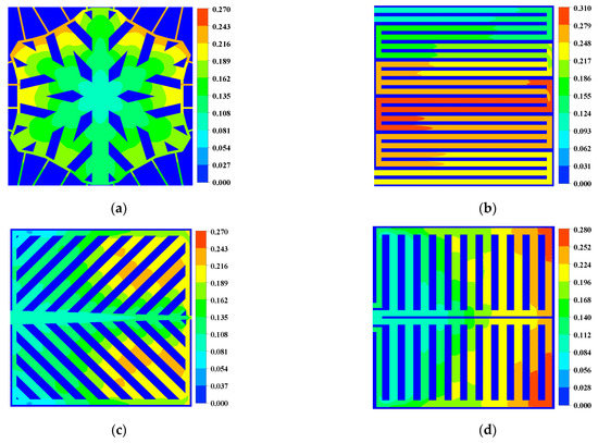
Figure 7.
Water mass fraction in cathode channel (0.8 V): (a) Snowflake bionic flow channel; (b) dual serpentine flow channel; (c) leaf-shape bionic flow channel; (d) lung-shape bionic flow channel.
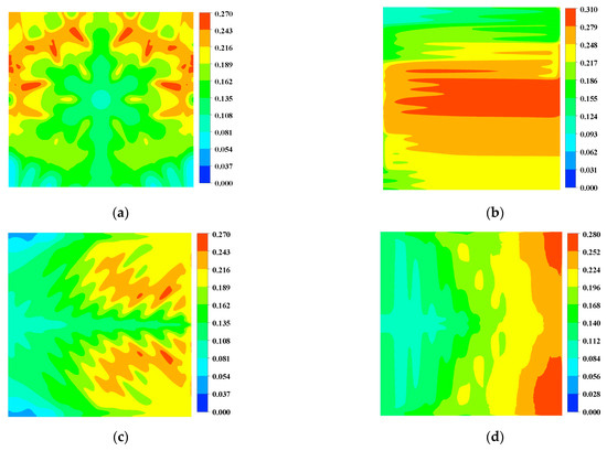
Figure 8.
Water mass fraction in cathode diffusion layer (0.8 V): (a) Snowflake bionic flow channel; (b) dual serpentine flow channel; (c) leaf-shape bionic flow channel; (d) lung-shape bionic flow channel.
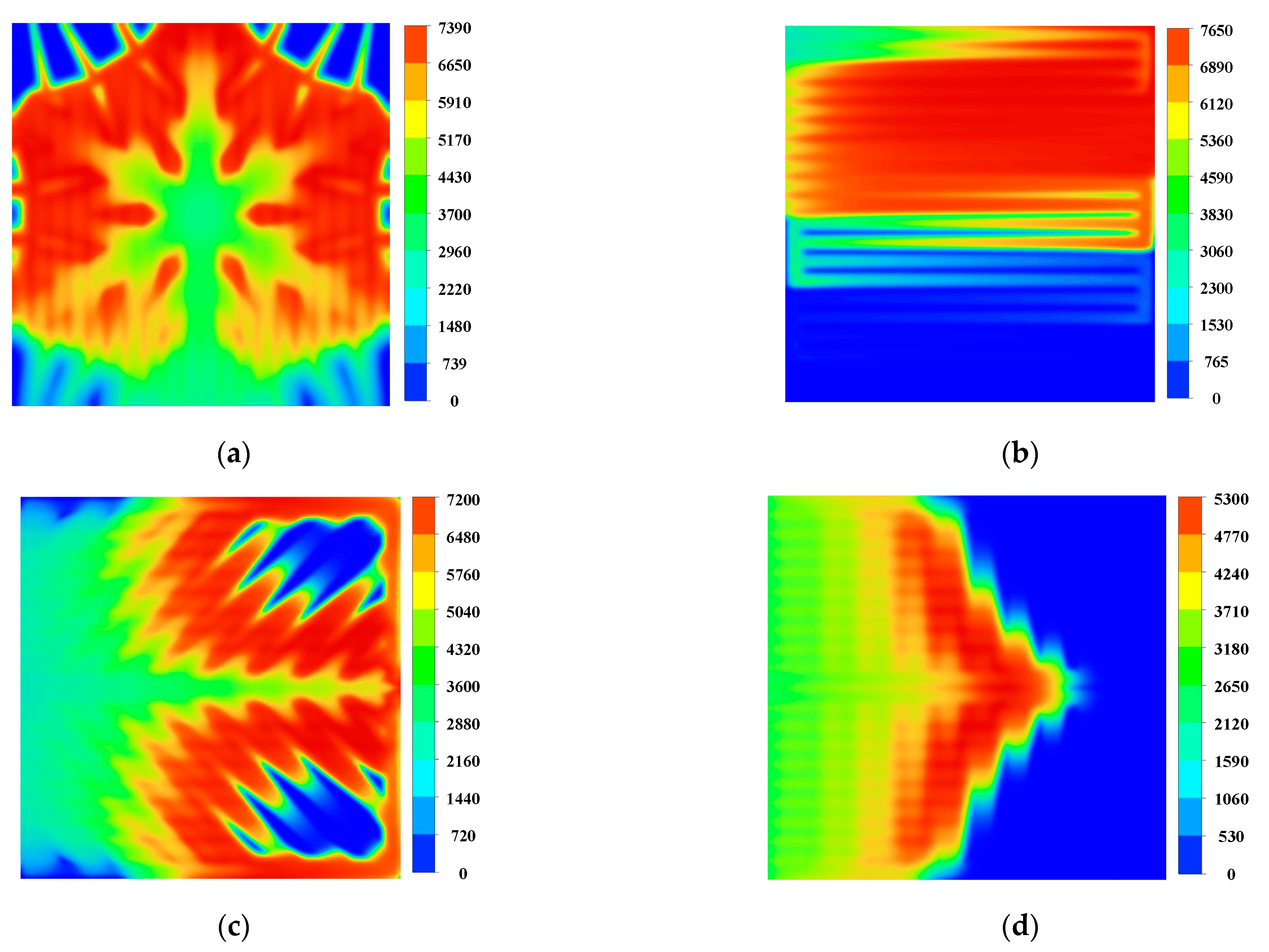
The current density of the fuel cell can directly reflect the electrochemical reaction of the cell, which can specifically reflect the cell’s performance locally and provide guidance to the improving design of the fuel cell. Figure 9 shows the current density distribution in the membrane. The gas flow rate is the largest in the inlet region, so that the electrochemical reaction does not have time to occur. In this region, the current density generated will be smaller than other parts. The current density in the second half of the flow channel is almost zero, with a surface average current density of 3641.78 A m−2. The oxygen supply in the double serpentine flow channel is insufficient. At the same time, there is a right angle at the turn, where a current surge occurs. The leaf-shaped and lung-shaped channels also have local fuel supply deficiencies because of poor water management, with face-averaged current densities of 4099.66 A m−2 and 1980.22 A m−2. On the other hand, the snowflake-shaped channel is relatively homogeneous, with no right angles present in the primary reaction area and a face-averaged current density of 4656.20 A m−2, which is 135.14% higher than that of the lung-shaped channel.

Figure 9.
The current density distribution of the membrane (A m−2) (0.8 V): (a) Snowflake bionic flow channel; (b) dual serpentine flow channel; (c) leaf-shape bionic flow channel; (d) lung-shape bionic flow channel.
3.3. Muti-Objection and Multi-Parameter Optimization of the Snowflake Flow Channel
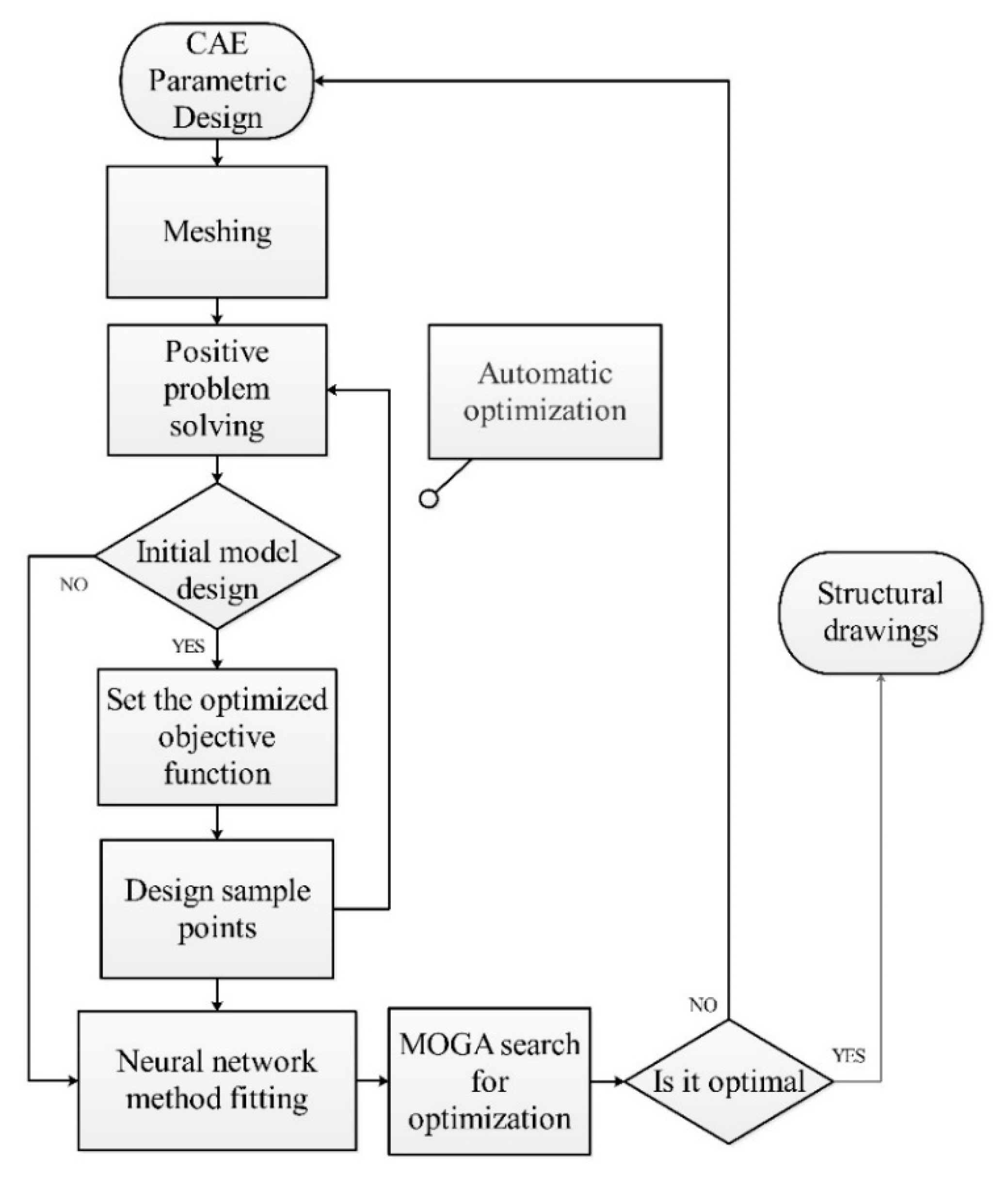
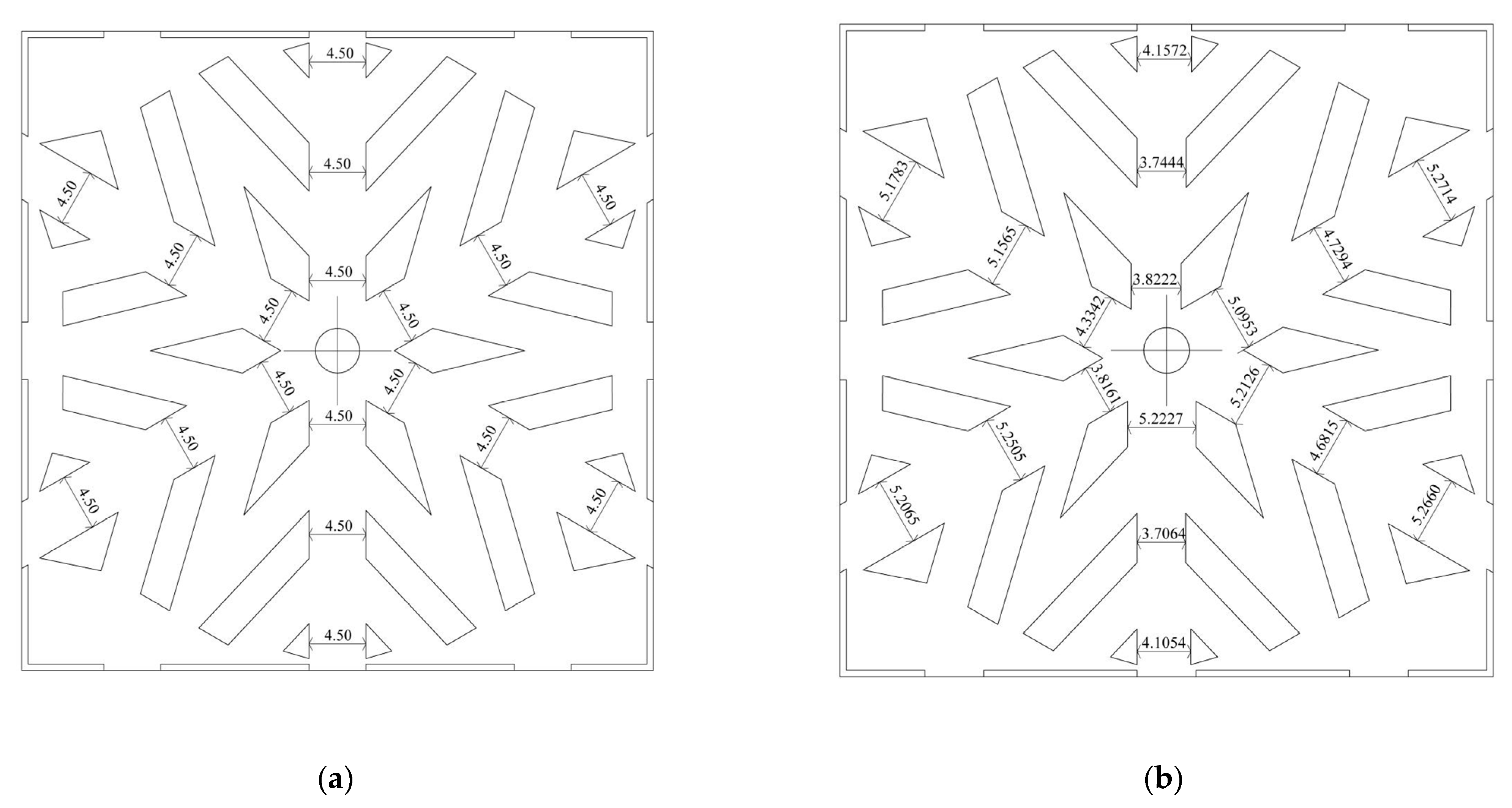
In summary, the snowflake flow channel has proven effective for oxygen diffusion and water removal with less pressure drop punished. However, we can see the limitation of this novel flow channel from the local transport characteristics. For example, the pressure drop of the snowflake flow channel is so tiny that the oxygen flows through the fuel cell too quickly to be consumed. Secondly, the area ratio of the channel is too small. The ribs around the flow channel block the gas flow and diffuse to the diffusion layer. The existence of the capillary outlet will hinder the transportation of water to a certain extent. Such limitations can be improved by using topology optimization. To do this, the parametric design was implemented to search the optimization value of flow channel topology automatically, as shown in Figure 10. There are 18 designed parameters in the snowflake channels shown in Figure 11, which are the input parameters of the optimization. The selected input parameter is the rib spacing of the six main roads, the mass flow of each exit, and the degree of deviation between them, as shown in Table 4 and Figure 11. The optimized objective is the uniform mass flow rates of 12 cathode outlets. To quantize this effect, a new uniform parameter, which is the differences among these flow rates of 12 outlets, is defined as,
P31 = (P19 − P20) × 2 + (P19 − P21) × 2 + (P23 − P22) × 2 + (P23 − P24) × 2 +
(P25 − P26) × 2 + (P25 − P27) × 2 + (P29 − P28) × 2 + (P29 − P30) × 2
(P25 − P26) × 2 + (P25 − P27) × 2 + (P29 − P28) × 2 + (P29 − P30) × 2
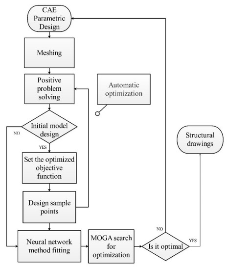
Figure 10.
Flow diagram of MOGA optimization for the snowflake flow channel fuel cells.
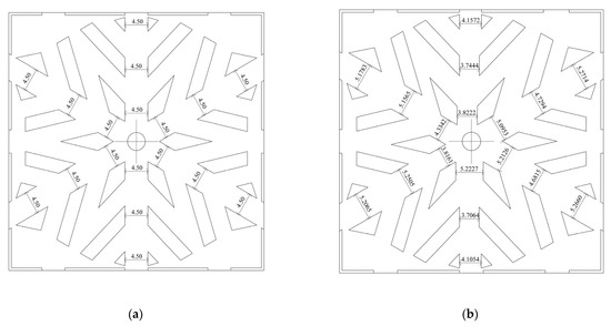
Figure 11.
The MOGA optimization for snowflake flow channel fuel cell: (a) initial design parameters; (b) optimized parameters.
Table 4.
Multi-objective genetic algorithm parameters.
4. Conclusions
In this work, we propose a snowflake-shaped bionic channel design by integrating the advantages of the leaf vein-shaped and lung-shaped channels. A 3D multi-physics fuel cell model is used to verify the feasibility and superiority of the bionic snowflake design in improving fuel cell performance and reducing the pumping work. The local pressure distribution, oxygen distribution, water distribution, and current density distribution are used to reveal the enhancement mechanism of the new snowflake flow channel. The multi-objective and multi-parameter genetic algorithm optimization further improves the flow uniformity. The main conclusions are as follows.
(1) In overall performance, particularly in the concentration polarization, the snowflake flow channel fuel cell is better than the leaf flow channel, the lung flow channel, and the dual serpentine flow channel. For the peak power density, the snowflake channel design has a 27% improvement over the leaf vein channel, 66% improvement over the lung channel, and 45.5% improvement over the dual serpentine channel.
(2) The snowflake bionic flow channel has significant superiority in reducing pressure drop punishment for the fuel cell. Such superiority can fully diffuse the reaction gas, resulting in a uniform oxygen distribution in the entire flow channel, the diffusion layer. Moreover, the concentration polarization region of the entire fuel cell is delayed. The average current density in the membrane cross section is 27.86% larger than the dual serpentine flow channel, 13.58% larger than the leaf flow channel, and 135.14% larger than the lung flow channel.
(3) With a MOGA optimization, the snowflake shape-improved flow field is optimized to improve the uniformity of the entire flow field. The degree of deviation of the mass flow of each outlet before and after optimization was reduced by 29.98%.
Author Contributions
Conceptualization, Y.L. and J.B.; methodology, M.T.; writing—original draft preparation, Y.L. and J.B.; writing—review and editing, G.L.; visualization, M.T.; supervision, G.L. All authors have read and agreed to the published version of the manuscript.
Funding
The authors acknowledge financial support from the National Natural Science Foundation of China (Nos. 52076074 and 12005217). Young Elite Scientists Sponsorship Program by CAST(No. 2019QNRC001).
Institutional Review Board Statement
Not applicable.
Informed Consent Statement
Not applicable.
Data Availability Statement
Not applicable.
Conflicts of Interest
The authors declare no conflict of interest.
Nomenclature
| Par. | Definitions | Par. | Definitions |
| Pop | Operating pressure, Pa | ε | Porosity |
| R | Universal gas constant, 8.314 J mol−1 K−1 | ρ | Density, kg m−3 |
| T | Operating temperature, K | u | Velocity vector, m s−1 |
| Xk | Mole fraction of substance | μ | Viscosity, kg m−1 s−1 |
| Ck | Mass fraction of substance | ƞ | Overpotential |
| CF | Quadratic drag factor | λ | Water content in membrane |
| kp | Permeability, m2 | ρdry | Membrane dry density, kg m−3 |
| krg | Relative permeability of the gaseous mixture | σs | Electron conductivity, s m−1 |
| Dk,eff | Effective diffusion coefficient of substance k | σm | Proton conductivity, s m−1 |
| F | Faraday constant, 96.487 °C mol−1 | Φs | Electronic phase potential, V |
| j | Transfer current density, A m−3 | Φm | Ionic phase potential, V |
| M | Molecular weight, kg mol−1 | nd | Electro-osmotic drag coefficient |
| im | Current density in the membrane, A m−2 | Pc | Capillary pressure, Pa |
| Mm | Membrane equivalent weight, kg mol−1 | Subscripts | |
| Dλ | Water diffusivity in the membrane | a | Anode |
| Aj0 | Exchange current density, A m−3 | c | Cathode |
| C | Mass fraction | l | Liquid phase |
| Vcell | Operating voltage v | ref | Reference value |
References
- Damian-Ascencio, C.E.; Saldaa-Robles, A.; Hernandez-Guerrero, A.; Cano-Andrade, S. Numerical modeling of a proton exchange membrane fuel cell with tree-like flow field channels based on an entropy generation analysis. Energy 2017, 133, 306–316. [Google Scholar] [CrossRef]
- Rostami, L.; Nejad, P.M.G.; Vatani, A. A numerical investigation of serpentine flow channel with different bend sizes in polymer electrolyte membrane fuel cells. Energy 2016, 97, 400–410. [Google Scholar] [CrossRef]
- Qi, Z.; Kaufman, A. PEM fuel cell stacks operated under dry-reactant conditions. J. Power Sources 2002, 109, 469–476. [Google Scholar] [CrossRef]
- Karthikeyan, M.; Muthukumar, M.; Kannan, V.M.; Thanarajan, K.; Maiyalagan, T.; Hong, C.-W.; Jothi, V.R.; Yi, S.-C. Adoption of novel porous inserts in the flow channel of pem fuel cell for the mitigation of cathodic flooding. Int. J. Hydrogen Energy 2020, 45, 7863–7872. [Google Scholar] [CrossRef]
- Spernjak, D.; Prasad, A.K.; Advani, S.G. In situ comparison of water content and dynamics in parallel, single-serpentine, and interdigitated flow fields of polymer electrolyte membrane fuel cells. J. Power Sources 2010, 195, 3553–3568. [Google Scholar] [CrossRef]
- Wilberforce, T.; El Hassan, Z.; Ogungbemi, E.; Ijaodola, O.; Khatib, F.; Durrant, A.; Thompson, J.; Baroutaji, A.; Olabi, A. A comprehensive study of the effect of bipolar plate (BP) geometry design on the performance of proton exchange membrane (PEM) fuel cells. Renew. Sustain. Energy Rev. 2019, 111, 236–260. [Google Scholar] [CrossRef]
- Atyabi, A.; Afshari, E.; Wongwises, S.; Yan, W.-M.; Hadjadj, A.; Shadloo, M.S. Effects of assembly pressure on PEM fuel cell performance by taking into accounts electrical and thermal contact resistances. Energy 2019, 179, 490–501. [Google Scholar] [CrossRef]
- Li, X.; Sabir, I. Review of bipolar plates in PEM fuel cells: Flow-field designs. Int. J. Hydrogen Energy 2005, 30, 359–371. [Google Scholar] [CrossRef]
- Tüber, K.; Oedegaard, A.; Hermann, M.; Hebling, C. Investigation of fractal flow-fields in portable proton exchange membrane and direct methanol fuel cells. J. Power Sources 2004, 131, 175–181. [Google Scholar] [CrossRef]
- Neto, D.M.; Oliveira, M.C.; Alves, J.L.; Menezes, L.F. Numerical study on the formability of metallic bipolar plates for proton exchange membrane (PEM) fuel cells. Metals 2019, 9, 810. [Google Scholar] [CrossRef] [Green Version]
- Jang, J.-Y.; Cheng, C.-H.; Liao, W.-T.; Huang, Y.-X.; Tsai, Y.-C. Experimental and numerical study of proton exchange membrane fuel cell with spiral flow channels. Appl. Energy 2012, 99, 67–79. [Google Scholar] [CrossRef]
- Friess, B.R.; Hoorfar, M. Development of a novel radial cathode flow field for PEMFC. Int. J. Hydrogen Energy 2012, 37, 7719–7729. [Google Scholar] [CrossRef]
- Cano-Andrade, S.; Hernández-Guerrero, A.; Von Spakovsky, M.; Damian, C.; Rubio-Arana, J. Current density and polarization curves for radial flow field patterns applied to PEMFCs (Proton Exchange Membrane Fuel Cells). Energy 2010, 35, 920–927. [Google Scholar] [CrossRef]
- Guo, N.; Leu, M.C.; Koylu, U.O. Network based optimization model for pin-type flow field of polymer electrolyte membrane fuel cell. Int. J. Hydrogen Energy 2013, 38, 6750–6761. [Google Scholar] [CrossRef]
- Wilberforce, T.; Khatib, F.; Ijaodola, O.; Ogungbemi, E.; El-Hassan, Z.; Durrant, A.; Thompson, J.; Olabi, A. Numerical modelling and CFD simulation of a polymer electrolyte membrane (PEM) fuel cell flow channel using an open pore cellular foam material. Sci. Total Environ. 2019, 678, 728–740. [Google Scholar] [CrossRef]
- Wang, X.-D.; Lu, G.; Duan, Y.-Y.; Lee, D.-J. Numerical analysis on performances of polymer electrolyte membrane fuel cells with various cathode flow channel geometries. Int. J. Hydrogen Energy 2012, 37, 15778–15786. [Google Scholar] [CrossRef]
- Roshandel, R.; Arbabi, F.; Moghaddam, G.K. Simulation of an innovative flow-field design based on a bio inspired pattern for PEM fuel cells. Renew. Energy 2012, 41, 86–95. [Google Scholar] [CrossRef]
- Guo, N.N.; Leu, M.C.; Koylu, U.O. Bio-inspired flow field designs for polymer electrolyte membrane fuel cells. Int. J. Hydrogen Energy 2014, 39, 21185–21195. [Google Scholar] [CrossRef]
- Saripella, B.P.; Koylu, U.O.; Leu, M.C. Experimental and computational evaluation of performance and water management characteristics of a bio-inspired proton exchange membrane fuel cell. J. Fuel Cell Sci. Technol. 2015, 12, 061007. [Google Scholar] [CrossRef]
- Ouellette, D.; Ozden, A.; Ercelik, M.; Colpan, C.O.; Ganjehsarabi, H.; Li, X.; Hamdullahpur, F. Assessment of different bio-inspired flow fields for direct methanol fuel cells through 3D modeling and experimental studies. Int. J. Hydrogen Energy 2017, 43, 1152–1170. [Google Scholar] [CrossRef]
- Ozden, A.; Ercelik, M.; Ouellette, D.; Colpan, C.O.; Ganjehsarabi, H.; Hamdullahpur, F. Designing, modeling and performance investigation of bio-inspired flow field based DMFCs. Int. J. Hydrogen Energy 2017, 42, 21546–21558. [Google Scholar] [CrossRef]
- Trogadas, P.; Cho, J.I.S.; Neville, T.P.; Marquis, J.; Wu, B.; Brett, D.J.L.; Coppens, M.-O. A lung-inspired approach to scalable and robust fuel cell design. Energy Environ. Sci. 2018, 11, 136–143. [Google Scholar] [CrossRef] [Green Version]
- Cho, J.; Neville, T.; Trogadas, P.; Bailey, J.; Shearing, P.; Brett, D.; Coppens, M.-O. Capillaries for water management in polymer electrolyte membrane fuel cells. Int. J. Hydrogen Energy 2018, 43, 21949–21958. [Google Scholar] [CrossRef]
- Cho, J.; Neville, T.; Trogadas, P.; Meyer, Q.; Wu, Y.; Ziesche, R.; Boillat, P.; Cochet, M.; Manzi-Orezzoli, V.; Shearing, P.; et al. Visualization of liquid water in a lung-inspired flow-field based polymer electrolyte membrane fuel cell via neutron radiography. Energy 2019, 170, 14–21. [Google Scholar] [CrossRef]
- Currie, J.M. Biomimetic Design Applied to the Redesign of a Pem Fuel Cell Flow Field; University of Toronto: Toronto, ON, Canada, 2010. [Google Scholar]
- Abdulla, S.; Patnaikuni, V.S. Detailed analysis of polymer electrolyte membrane fuel cell with enhanced cross-flow split serpentine flow field design. Int. J. Energy 2019, 43, 2806–2820. [Google Scholar] [CrossRef]
- Arvay, A.; French, J.; Wang, J.-C.; Peng, X. Modeling and simulation of biologically inspired flow field designs for proton exchange membrane fuel cells. Open Electrochem. J. 2015, 6, 1–9. [Google Scholar]
- Joshua, H. Bio-Inspired Flow Fields for PEM Fuel Cells Decoupling Pressure and Distribution Effects on Performance and Identifying Design Opportunities; Missouri University of Science and Technology: Rolla, MO, USA, 2017. [Google Scholar]
- Asadzade, M.; Shamloo, A. Design and simulation of a novel bipolar plate based on lung-shaped bio-inspired flow pattern for PEM fuel cell. Int. J. Energy Res. 2017, 41, 1730–1739. [Google Scholar] [CrossRef]
- Brkić, D.; Praks, P. Air-forced flow in proton exchange membrane fuel cells: Calculation of fan-induced friction in open-cathode conduits with virtual roughness. Processes 2020, 8, 686. [Google Scholar] [CrossRef]
- Barreras, F.; López, A.M.; Lozano, A.; Barranco, J.E. Experimental study of the pressure drop in the cathode side of air-forced open-cathode proton exchange membrane fuel cells. Int. J. Hydrogen Energy 2011, 36, 7612–7620. [Google Scholar] [CrossRef]


Publisher’s Note: MDPI stays neutral with regard to jurisdictional claims in published maps and institutional affiliations. |
© 2022 by the authors. Licensee MDPI, Basel, Switzerland. This article is an open access article distributed under the terms and conditions of the Creative Commons Attribution (CC BY) license (https://creativecommons.org/licenses/by/4.0/).