
Trajectory Modulation for Impact Reducing of Lower-Limb Exoskeletons

Abstract
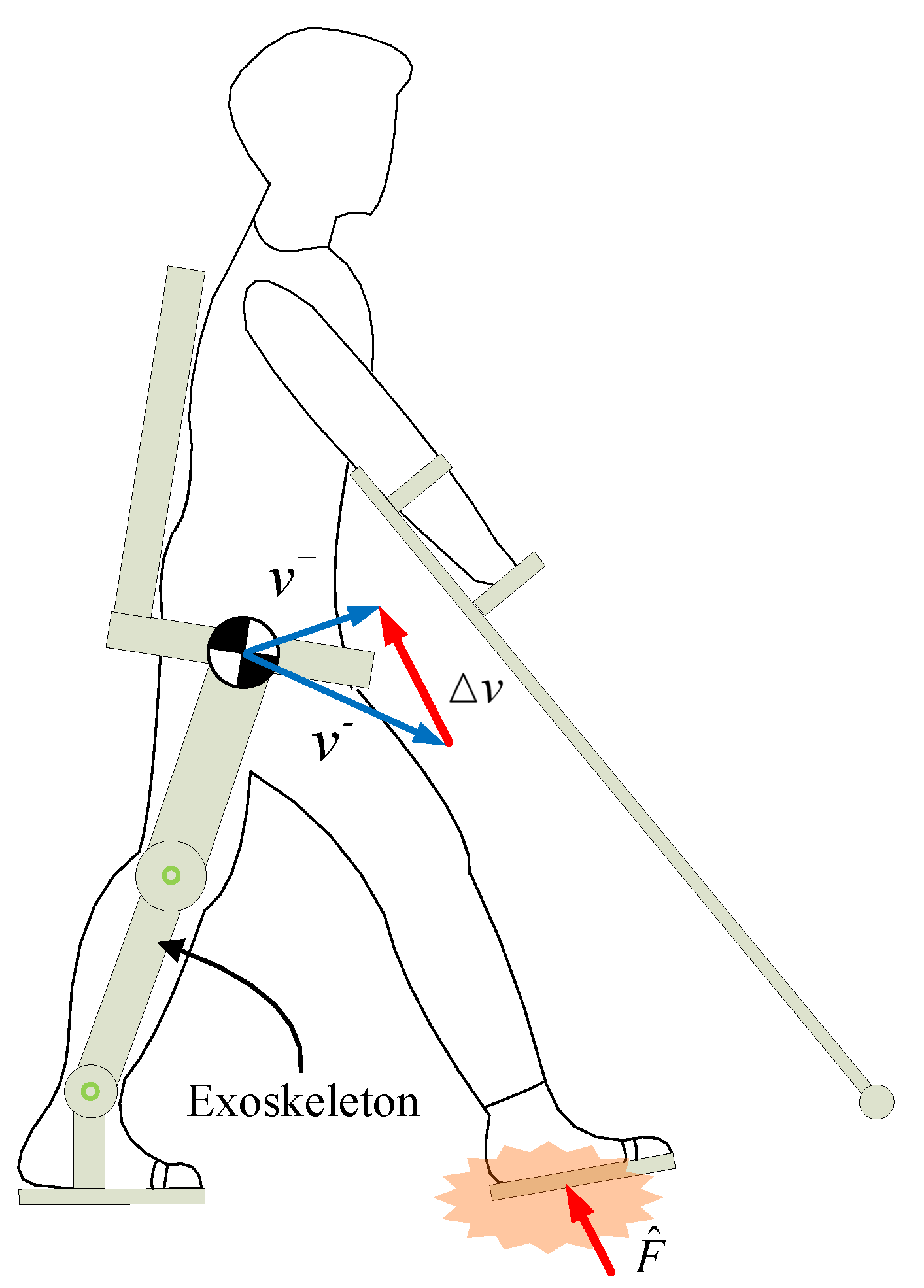
:1. Introduction
- An optimized knee trajectory modulation (OKTM) is proposed for walking-impact reduction in lower limb exoskeletons.
- An HTM is proposed to compensate for excessive torso pitch deflection caused by the OKTM.
- The proposed approach is validated by simulations and the AIDER lower-exoskeleton system. Results show that the OKTM is effective in reducing the PGRF and that the HTM can reduce torso deflection during walking.
2. Methods
2.1. Optimized Knee-Trajectory Modulation
2.1.1. Optimized Shock-Absorption Model
2.1.2. Knee-Trajectory Modulator
2.2. Hip-Trajectory Modulation
3. Experiments and Discussion
3.1. Simulation of the OKTM
3.2. Experiments on the AIDER Exoskeleton System
4. Conclusions and Future Works
Author Contributions
Funding
Institutional Review Board Statement
Informed Consent Statement
Data Availability Statement
Conflicts of Interest
References
- Astorino, T.A.; Harness, E.T. Effect of chronic activity-based the rapy on bone mineral density and bone turnover in persons with spinal cord injury. Arbtsphysiologie 2013, 113, 3027–3037. [Google Scholar]
- Fineberg, D.B.; Asselin, P.; Harel, N.Y.; Agranova-Breyter, I.; Kornfeld, S.D.; Bauman, W.A.; Spungen, A.M. Vertical ground reaction force-based analysis of powered exoskeleton-assisted walking in persons with motor-complete paraplegia. J. Spinal Cord Med. 2013, 36, 313–321. [Google Scholar] [CrossRef] [PubMed] [Green Version]
- Simonsen, C.S.; Celius, E.G.; Brunborg, C.; Tallaksen, C.; Moen, S.M. Bone mineral density in patients with multiple sclerosis, hereditary ataxia or hereditary spastic paraplegia after at least 10 years of disease—A case control study. BMC Neurol. 2016, 16, 252. [Google Scholar] [CrossRef] [PubMed] [Green Version]
- Esquenazi, A.; Talaty, M.; Packel, A.; Saulino, M. The ReWalk powered exoskeleton to restore ambulatory function to individuals with thoracic-level motor-complete spinal cord injury. Am. J. Phys. Med. Rehabil. 2012, 91, 911–921. [Google Scholar] [CrossRef] [PubMed] [Green Version]
- Read, E.; Woolsey, C.; Mcgibbon, C.A.; O’Connell, C. Physiotherapists’ Experiences Using the Ekso Bionic Exoskeleton with Patients in a Neurological Rehabilitation Hospital: A Qualitative Study. Rehabil. Res. Pract. 2020, 2020, 1–8. [Google Scholar] [CrossRef] [PubMed]
- Tefertiller, C.; Hays, K.; Jones, J.; Jayaraman, A.; Hartigan, C.; Bushnik, T.; Forrest, G. Initial Outcomes from a Multicenter Study Utilizing the Indego Powered Exoskeleton in Spinal Cord Injury. Top. Spinal Cord Inj. Rehabil. 2018, 24, 78–85. [Google Scholar] [CrossRef]
- Donelan, J.M.; Kram, R.; Kuo, A.D. Mechanical work for step-to-step transitions is a major determinant of metabolic cost of human walking. J. Exp. Biol. 2003, 205, 3717–3727. [Google Scholar] [CrossRef]
- Zelik, K.E.; Kuo, A.D. Human walking isn’t all hard work: Evidence of soft tissue contributions to energy dissipation and return. J. Exp. Biol. 2010, 213, 4257–4264. [Google Scholar] [CrossRef] [Green Version]
- Koyama, K.; Umezawa, J.; Kurihara, T.; Naito, H.; Yanagiya, T. The Influence of Position and Area of Shock Absorbing Material of Shoes on Ground Reaction Force during Walking. IFMBE Proc. 2010, 31, 262–265. [Google Scholar]
- Ueda, J.; Turkseven, M.; Kim, E.; Lowery, Q.; Mayo, M. Shock absorbing exoskeleton for vertical mobility system: Concept and feasibility study. In Proceedings of the 2018 IEEE/RSJ International Conference on Intelligent Robots and Systems (IROS), Madrid, Spain, 1–5 October 2018; pp. 3342–3349. [Google Scholar]
- Park, J.; Lee, D.; Park, k.; Kong, K. Reduction of Ground Impact of a Powered Exoskeleton by Shock Absorption Mechanism on the Shank. In Proceedings of the 2021 International Conference on Robotics and Automation (ICRA), Xian, China, 30 May–5 June 2021; pp. 2085–2090. [Google Scholar]
- Zelik, K.E.; Huang, T.W.P.; Adamczyk, P.G.; Kuo, A.D. The role of series ankle elasticity in bipedal walking. J. Theor. Biol. 2014, 346, 75–85. [Google Scholar] [CrossRef] [Green Version]
- Huang, T.W.P.; Shorter, K.A.; Adamczyk, P.G.; Kuo, A.D. Mechanical and energetic consequences of reduced ankle plantar-flexion in human walking. J. Exp. Biol. 2015, 218, 3541–3550. [Google Scholar] [PubMed] [Green Version]
- Malcolm, P.; Quesada, R.E.; Caputo, J.M.; Collins, S.H. The influence of push-off timing in a robotic ankle-foot prosthesis on the energetics and mechanics of walking. J. Neuroeng. Rehabil. 2015, 12, 1–15. [Google Scholar] [CrossRef] [PubMed] [Green Version]
- Yue, H.; Mombaur, K. Analysis of human leg joints compliance in different walking scenarios with an optimal control approach. IFAC Int. Workshop Period. Control. Syst. 2016, 49, 99–106. [Google Scholar]
- Seyfarth, A.; Lipfert, S.; Rummel, J.; Maus, M.; Maykranz, D. Walking and running: How leg compliance shapes the way we move. In Modeling, Simulation and Optimization of Bipedal Walking; Springer: Berlin/Heidelberg, Germany, 2013; pp. 211–222. [Google Scholar]
- Gard, S.A.; Childress, D.S. The effect of pelvic list on the vertical displacement of the trunk during normal walking. Gait Posture 1997, 5, 233–238. [Google Scholar] [CrossRef]
- Russell, F.; Takeda, Y.; Kormushev, P.; Vaidyanathan, R.; Ellison, P. Stiffness Modulation in a Humanoid Robotic Leg and Knee. IEEE Robot. Autom. Lett. 2021, 6, 2563–2570. [Google Scholar] [CrossRef]
- Liu, N.W. The effect of muscle stiffness and damping on simulated impact force peaks during running. J. Biomech. 1999, 32, 849–856. [Google Scholar]
- Zhang, L.; Song, G.; Zou, C.; Cheng, H.; Huang, R.; Qiu, J. Knee trajectory modulation for impact reducing of lower limb exoskeletons. In Proceedings of the 2021 IEEE International Conference on Robotics and Biomimetics (ROBIO), Sanya, China, 6–10 December 2021; pp. 160–167. [Google Scholar]
- Adamczyk, P.G.; Kuo, A.D. Redirection of center-of-mass velocity during the step-to-step transition of human walking. J. Exp. Biol. 2009, 212, 2668–2678. [Google Scholar] [CrossRef] [Green Version]
- Cestari, M.; Sanz-Merodio, D.; Arevalo, J.C.; Garcia, E. An Adjustable Compliant Joint for Lower-Limb Exoskeletons. IEEE/ASME Trans. Mechatron. 2014, 20, 889–898. [Google Scholar] [CrossRef] [Green Version]
- Cestari, M.; Sanz-Merodio, D.; Garcia, E. Preliminary Assessment of a Compliant Gait Exoskeleton. Soft Robot 2017, 2, 135–146. [Google Scholar] [CrossRef]
- Akl, A.R.; Baca, A.; Richards, J.; Conceicao, F. Leg and lower limb dynamic joint stiffness during different walking speeds in healthy adults—ScienceDirect. Gait Posture 2020, 82, 294–300. [Google Scholar] [CrossRef]
- Jeon, H.M.; Heo, J.H.; Choi, E.B.; Eom, G.M. Upper body axial rotations in different age-groups during level walking. J. Mech. Med. Biol. 2019, 19, 1940049. [Google Scholar] [CrossRef]
- Spinal Cord Injury Levels & Classification. Available online: http://www.sci-info-pages.com/levels.html (accessed on 4 April 2021).


| Description | Value |
|---|---|
| CoM mass m | 80 kg |
| Gravitational acceleration g | 9.8 m/s |
| Calf length | 0.44 m |
| Thigh length | 0.41 m |
| Initial ground contact knee angle | 5 deg |
| Initial ground contact velocities | 0.1 m/s |
| Initial ground contact velocities | 0.3 m/s |
| Damping ratio of OSAM | |
| Landing leg bodyweight supported rate | |
| The angle |
| Initial Ground Contact Velocities m/s | |||||
|---|---|---|---|---|---|
| [N/m] | [N] | [deg] | [N] | Description | |
| A1 | 6000 | 250 | 37.4 | 647.6 | Excessive |
| B1 | 10,000 | 370 | 21.9 | 635 | Optimal set |
| C1 | 18,000 | 485 | 9.8 | 727.4 | Inferior |
| D1 | 19,200 | 575 | 5.5 | 825.4 | Inferior & leg vibrations |
| Initial Ground Contact Velocities m/s | |||||
|---|---|---|---|---|---|
| [N/m] | [N] | [deg] | [N] | Description | |
| A1 | 12000 | 200 | 28.4 | 793.8 | Excessive |
| B1 | 18,900 | 140 | 22 | 885.2 | Optimal set |
| C1 | 18,000 | 360 | 15.9 | 1087 | Inferior |
| D1 | 18,000 | 445 | 13.7 | 1172 | Inferior & leg vibrations |
| Description | Value |
|---|---|
| Pilot weight | 60 kg |
| Exoskeleton weight | 25 kg |
| Damping ratio of SAM | |
| Landing-leg bodyweight supported rate |
| Walking Gaits | k[N/m] (Mean) | Fpre [N] (Mean) | max[deg] (Mean) | PGRF [N] (Mean ± SD) | Decline |
|---|---|---|---|---|---|
| CG | / | / | / | 1140 ± 150 | / |
| MGA | 19140 | 350 | 15.4 | 1029 ± 87 | 10.70% |
| MGB | 19100 | 130 | 22 | 930 ± 45 | 22.50% |
| Walking Gaits | k[N/m] (Mean) | Fpre [N] (Mean) | max[deg] (Mean) | PGRF [N] (Mean ± SD) | Decline |
|---|---|---|---|---|---|
| CG | / | / | / | 1030 ± 138.5 | / |
| MGA | 18281 | 504.3 | 15.6 | 952 ± 71 | 8.10% |
| MGB | 14452 | 332.5 | 22 | 893 ± 60 | 15.30% |
| Maximum Torso Pitch Angle [deg] | Minimum Torso Pitch Angle [deg] | |
|---|---|---|
| (Mean ± SD) | (Mean ± SD) | |
| Walk without HTM | 6.53 ± 0.45 | −4.11 ± 0.51 |
| Walk with HTM | 6.22 ± 0.3 | 2.72 ± 0.25 |
Publisher’s Note: MDPI stays neutral with regard to jurisdictional claims in published maps and institutional affiliations. |
© 2022 by the authors. Licensee MDPI, Basel, Switzerland. This article is an open access article distributed under the terms and conditions of the Creative Commons Attribution (CC BY) license (https://creativecommons.org/licenses/by/4.0/).
Share and Cite
Zhang, L.; Song, G.; Zou, C.; Huang, R.; Cheng, H.; Hu, D. Trajectory Modulation for Impact Reducing of Lower-Limb Exoskeletons. Micromachines 2022, 13, 816. https://doi.org/10.3390/mi13060816
Zhang L, Song G, Zou C, Huang R, Cheng H, Hu D. Trajectory Modulation for Impact Reducing of Lower-Limb Exoskeletons. Micromachines. 2022; 13(6):816. https://doi.org/10.3390/mi13060816
Chicago/Turabian StyleZhang, Long, Guangkui Song, Chaobin Zou, Rui Huang, Hong Cheng, and Dekun Hu. 2022. "Trajectory Modulation for Impact Reducing of Lower-Limb Exoskeletons" Micromachines 13, no. 6: 816. https://doi.org/10.3390/mi13060816