In order to study the influence of the
ratio on the cutting process, a cut angle
ɣ = 8° is fixed. The cutting edge radius
rβ and the cutting height
hc are set at 2–5–8–10 µm and 2–4 µm respectively, as shown in
Table 5. Observation of the von Mises equivalent stress shows that whatever the cutting depth or the cutting edge radius, the maximum stress is in order of 1500 MPa in all cases.
On the other hand, the chip morphology and the stress field distribution are different depending on the case. Simulation results with a larger edge radius show that the shear zones merge to form a single zone. This explains the increase in the feed force
Ff for cases where the
ratio is less than one see
Figure 8. As a result, the material is hardened and the stress rises in front of the cutting edge, and in consequence, cutting forces rise as well.
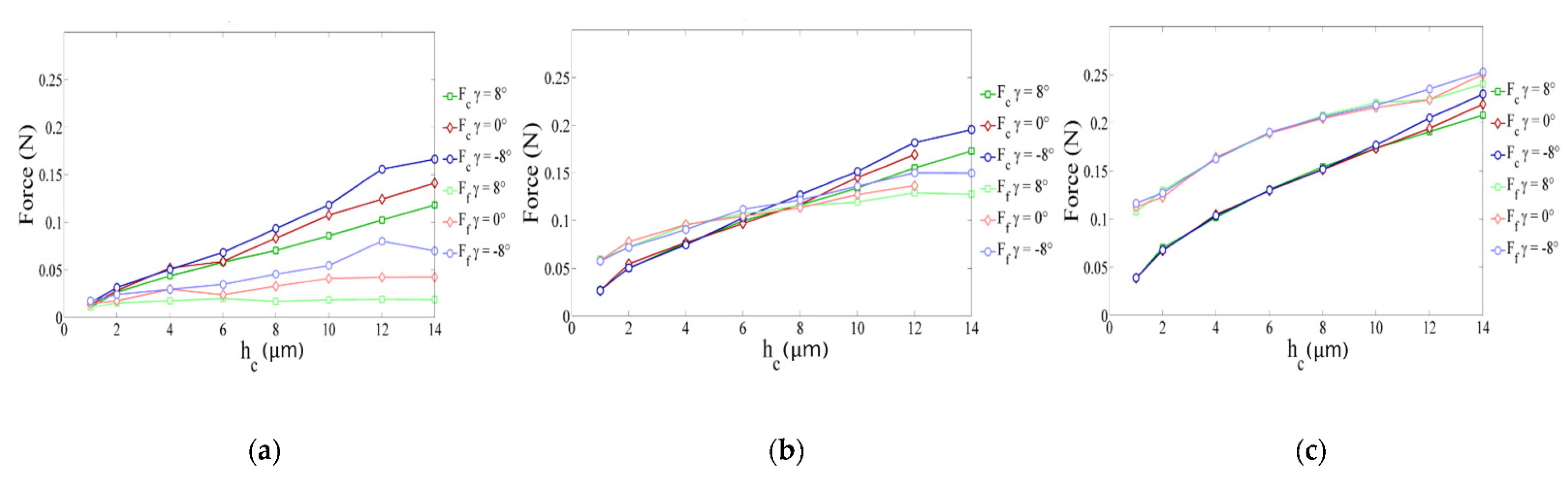
For the SPH method, the main studied parameters were the edge radius, the cutting depth and the cutting angle. Only three values of
hc (2, 11, 20 µm) and
(−8°, 0° et 8°) were studied. The
hc parameter varied between 1 and 14 µm. As noticed in the FE method, the maximum von Mises stress of 1320 MPa is reached in almost all cases.
Figure 9 shows the evolution of cutting forces (in absolute value) in the different cases (various values of edge radius, rake angle and cutting depth). Several points should be mentioned. Firstly,
rβ has a large influence on the cutting forces. Secondly, when
hc is smaller than
rβ (0.5
hc ≤
rβ ≤
hc) force curves overlap, which means that the cutting angle has no influence on cutting forces for small cutting depths
hc. For higher values of
hc, cutting forces depend on cutting angle, i.e., cutting forces increase when cutting angle decreases. Finally, for important values of
rβ, the cutting force component is lower than the feed force component (mainly when the cutting angle is no longer influencing). We can notice the independence of cutting forces from rake angle by plotting the obtained results as a function of cutting depth and cutting edge radius in
Figure 10. It is clear that for a ratio
less than 0.8, the feed force
Ff is greater than the cutting force
Fc. Likewise, the cutting angle no longer influences forces for a ratio
lesser than 1 and expresses a predominant plowing regime. Concerning the stress distribution observed from SPH simulations, we can notice that the dimensionless parameter
provides results completely independent of the edge radius value.
Figure 11 illustrates the geometry of the chip formation zone through the maximum of Von Mises stress as a function of
. We can see for low ratios of
, that the zone starts at the lowest point of the tool and then takes a comma shape without following the radiated part of the tool, suggesting the appearance of a dead zone. For the higher ratios, we obtain a band shape, which is common in the literature. It should be noticed that with the SPH model, the material flow near the cutting edge is highly reduced with important values of
. It corresponds to experimental observations made from quick stop tests in micro-cutting where a sticking phenomenon is clearly identified in this region of the chip for high values of edge radius [
11].
The two models show as outputs the distribution of von Mises stress, cutting force and chip shape in order to study the influence of tool geometry, especially the cutting edge radius on th ecutting process. Results show that in micro-cutting, maximum cutting force and Von Mises stress values are proportionally greater than in conventional machining. This is due to the reduction in the dimensions of the tool in regard to cutting depth.
With the FE model using a Lagrangian formulation, the cutting forces correspond well to the experimental results. High sensitivity to the hc/rβ ratio was observed from the stress field distribution and the chip morphology is consistent. We noticed that force values were higher than the experimental forces due to excessive element distortion using the Lagrangian approach.


 ,
, 


