1. Introduction
Electronics are becoming increasingly sophisticated while decreasing in size. For high-resolution displays, 0201 sized electronic chip parts and micro-LEDs of less than 100 μm have been developed [
1]. Microfiber assembly is also one of the most significant technologies for the advancement of information processing instruments [
2].
In conventional surface mounting technology (SMT), the suction force generated by compressed air is used mainly to pick up flat components. However, as the size of the chip decreases, a higher mounting speed and accuracy are required to achieve an adequate mounting density. Transfer printing technologies are feasible methods for assembling micro-LEDs [
3,
4,
5]. Mechanical grippers have important applications, such as medical operations on eyeballs [
6]. Shape memory polymers have also been investigated as a feasible micromanipulation method [
7,
8].
These techniques are based on the contact between the micro-object and the gripper, which may damage the targets. In contact-type grippers, it is necessary to control the gripping force while handling fragile objects. A noncontact-type gripper decreases the possibility of damaging the parts being handled.
In liquids, various non-contact micromanipulation methods have been reported, such as using steady streaming [
9,
10], electric fields [
11], and laser tweezers [
12,
13] for fragile positioning, such as biological cells and microorganisms.
In the atmosphere, ultrasonic levitation [
14,
15] and a liquid bridge force (hereinafter referred to as capillary force-based gripper) are categorized as non-contact grasping methods with self-alignment [
16,
17]. Several studies have been conducted on capillary force grippers for pick-and-place operations [
18,
19,
20,
21,
22]. Estimation of capillary force [
23,
24], and image processing technologies [
25,
26] are also significant research categories for the automation of micromanipulation and the classification of micro fossils [
25], micro particles [
26], soft robotics [
27], soft matters [
28], and biomedical fields.
In a previous article, Tanaka et al. reported a double nozzle gripper using two liquid transporting methods: a diaphragm pump and the capillary phenomenon [
22]. This study focused on the picking and placing of 1-mm sized objects with various shapes and did not describe a vision feedback control method for decreasing the positioning errors.
In this paper, we describe the details of the image processing procedure and the investigation of a size matching effect that influences final alignment accuracy [
28]. We also describe the attitude control by a shape matching effect between the nozzle shape and the picked object [
28,
29].
The remainder of the paper is structured as follows. We describe the static analysis in
Section 2; the mechanical design in
Section 3; the experimental setup, as shown in
Figure 1, in
Section 4; the image processing in
Section 5; the success rate, placing error, and attitude control in
Section 6; and concluding remarks and future research scope in
Section 7. (See also
Video S1 “Digest movie” for the outline).
2. Approximation of the Capillary Force
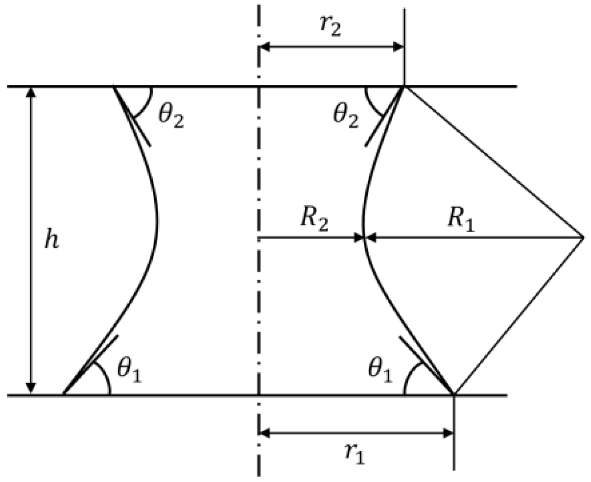
In this section, we estimate the capillary forces using the geometrical parameters of the objects when the top surface of the picked-up object is a plane.
Figure 2 shows the capillary bridge between the nozzle and the object. Here, the shape of the bottom of the liquid bridge is approximated to be circular. We defined the radius of the interface between the liquid bridge and the nozzle as
r2 and the radius of the interface between the liquid bridge and the object as
r1. In this case, assuming that the water spreads over the nozzle, we could estimate
r2 to be the radius of the nozzle.
h is the height of the liquid bridge, as shown in
Figure 2.
and
are the arc-approximated meniscus radii of the liquid bridges caused by the interfacial tension, respectively. In this case, it is the length of the wispiest part of the liquid bridge. Moreover,
and
are the contact angles between the object and the liquid and the nozzle and the liquid, respectively.
The capillary force is determined geometrically if the section curves of the meniscus are approximated as parts of the arc [
23,
24]. In this case,
and
are expressed as follows:
The mean curvature
C of the meniscus is determined as follows:
where
is positive. When the shape is convex,
is defined as negative. The difference in pressure across the interface, given by Laplace’s equation, is as follows:
Here,
is the surface tension, and
is given as follows:
Thus, the suction force acting on the flat plane (top surface of the cube) by the Laplace pressure
is expressed as follows:
The pulling force acting on the flat plane owing to the surface tension is given as follows:
From (6) and (7), the required capillary force
, which is the sum of
and
, is given as follows:
3. Design
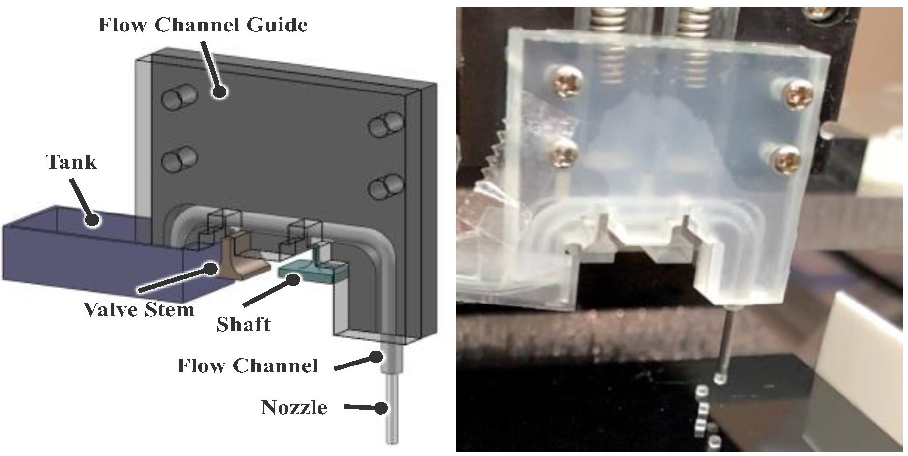
The gripper consists of a flow device, flow channel, tank, shaft, and valve stem, all fabricated from acrylic. The flow channel was made of a silicon tube. A stainless-steel tube was used at the end of the flow channel, which is called the nozzle. We used the valve stem and the shaft to refill water and form droplets, and we adopted a spring interlocking mechanism, developed by Hagiwara et al. [
21], to move them with the Z-stage.
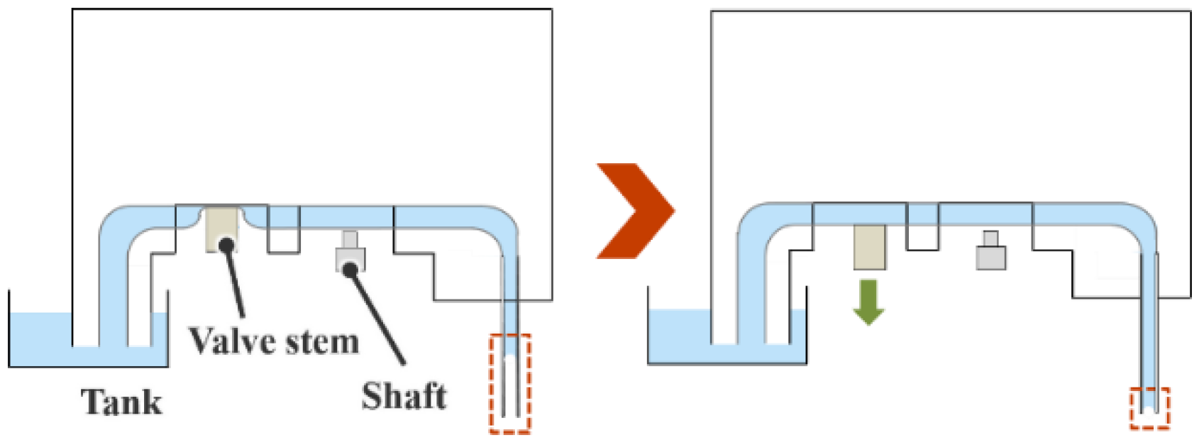
Figure 3 illustrates the filling of water in the channel through capillary action. As shown in the left panel, even if the water at the tip of the channel disappears owing to evaporation or experiment conduction, water can again be filled to the tip of the channel by pulling down the valve and opening the channel, as shown in the right panel.
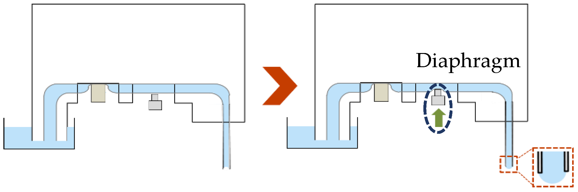
Figure 4 shows the formation of a droplet. When the water channel moves down, the valve closes the channel to prevent backflow (left panel), and the shaft then pushes the channel and forms the droplet at the channel tip using a diaphragm pump mechanism. Since the deformed volume of the diaphragm and the volume displaced from the shaft are almost equal, the volume of the droplet is determined by measuring the length of the shaft pushed in.
The object is picked up by contacting a formed droplet with the object. The object is placed by first contacting and applying a formed droplet to the place surface, and then contacting the bottom surface of the object picked up by the nozzle with the applied droplet.
Table 1 shows the parameters of the micro-objects used in the pick-and-place experiments.
In the experiments, we used various sizes and shapes of nozzles for each object. The experimental conditions and parameters used to calculate the estimated value of the capillary force for each condition are organized and shown in
Table 2; the estimated capillary forces are also shown.
,
, and
were typical values measured from the charge coupled device (CCD) camera image during the experiments. The surface tension
γ, measured by the ring method, was 72.9 mN/m; we used purified water as the liquid.
From
Table 2, it can be seen that the estimated capillary force had a much larger value than the corresponding gravitational force, and hence, this gripper could grasp the object under all conditions if there were no additional adhesive or electrostatic forces.
4. Experimental Setup
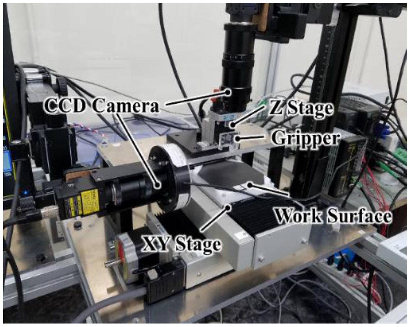
To increase the success rate of the pick-and-place, we developed an automatic pick-and-place with vision feedback function. The organization of the entire setup is shown in
Figure 5.
In this study, the work surface was positioned in the X- and Y-axis with a positioning resolution of 1 μm and a repeatability of ±0.5 μm (YA10A-L1, Kohzu Precision Co., Ltd., Kawasaki City, Japan). The gripper was connected to a linear stage (MMU-40X, Chuo Precision Industrial Co., Ltd., Tokyo, Japan) and moved along the Z-axis. It was also connected to the interlocking mechanism, which controls the shaft and the valve to form a droplet. The traverse limits of the XY- and Z-stages were ±50 mm and ±5 mm, respectively.
To measure the position of the samples, the vision feedback system by OpenCV was used. This system imported the image from the CCD camera set on top of the work bench. The camera had a resolution of 2432 × 2050 pixels (CV-H500M, KEYENCE Corp., Osaka, Japan). The CCD camera also attached to the side of the workbench, and it had a resolution of 1216 × 1025 pixels (CV-200C, KEYENCE Corp.). Each camera had a magnification lens (LA-LM510, Keyence Co.), and the depth of field was 1.28 mm.
The pixel resolutions of the top and side cameras were, approximately, 7 μm/pixel and 9 μm/pixel, respectively. We confirmed that the image processing and gravity center detection process in the vision feedback resulted in a final X- and Y-axis measurement resolution of 1 µm because of the averaging effect.
LabVIEW2018 (National Instruments, Austin, TX, USA) was used as the programming language, and OpenCV was used to conduct image processing. The detailed procedure for the image processing is described in
Section 5. The pick-and-place process is as follows:
- (1)
The object is placed within view of the top camera on the surface to measure the X- and Y- coordinates;
- (2)
The XY-stage is moved so that the placement position on the work surface is directly below the nozzle;
- (3)
The gripper is moved up and down by the Z-stage, and a droplet is applied to the work surface;
- (4)
The XY-stage is moved, and the object is placed directly under the nozzle;
- (5)
The gripper moves first down and then up to pick up the object;
- (6)
The XY-stage is moved such that the target placement position is directly below the nozzle grasping the object;
- (7)
The gripper moves down to place the picked-up object on the pre-applied droplet of (3);
- (8)
The XY-stage is moved such that the object is within view of the CCD camera to measure the X- and Y- coordinates.
In steps (3), (5), and (7) of the above process, the amount of Z-stage movement is calculated and determined by the image processing program written in Python from images captured by the side camera.
5. Image Processing
In this section, we explain the vision feedback system. The program used Open CV by Python. The system was used when applying place droplets, picking up, and placing objects.
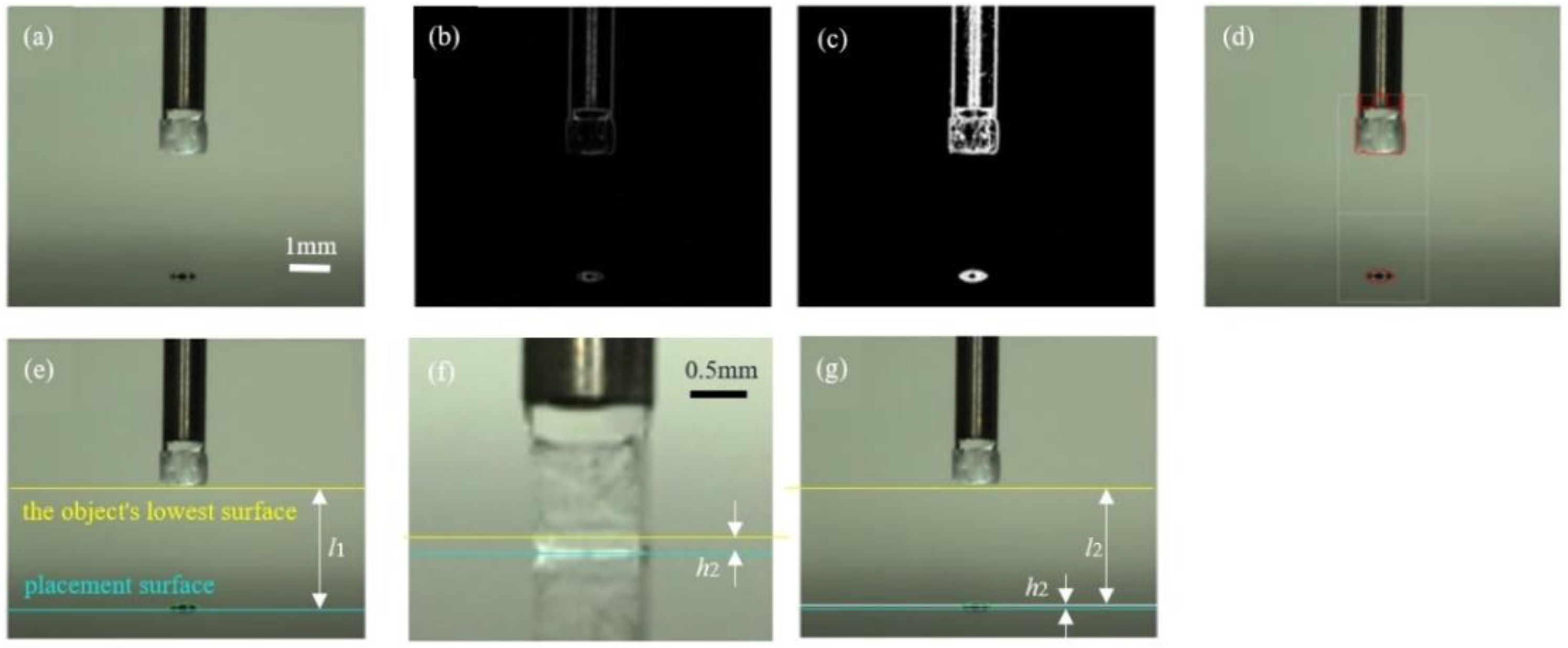
Figure 6 shows the image of the process of the vision feedback system in placement, and this process is described as follows:
- (1)
The side camera captures the image so that both the object and the place droplets are visible (
Figure 6a);
- (2)
The captured image is imported to the PC and the Sobel filter is applied (
Figure 6b).
- (3)
Next, the image is binarized by the threshold (
Figure 6c);
- (4)
The image is then used to detect the contour of the object (
Figure 6d);
- (4)
The distance
between the object and the place surface is calculated from the coordinates of the lowest surface of the object (
Figure 6e);
- (6)
In this experiment, the parameter is the liquid bridge height
h2 between the object and the place surface at placing (
Figure 6f). Thus, from
h2 and
, the stage descent amount
is determined as follows:
- (7)
The amount of Z-stage descent determined in (6) is fed back to the control (
Figure 6g).
As described in step 6, we used
h2 as a parameter in this experiment. Here,
Table 3 shows the set values of
h2 for each experimental condition.
Here, the condition values of (C1)–(C5) are the same as in
Table 2. We conducted the pick-and-place experiment 10 times for each condition.
6. Experiments
6.1. Comparison of Results with Height h2
We conducted the pick-and-place operation under the five conditions.
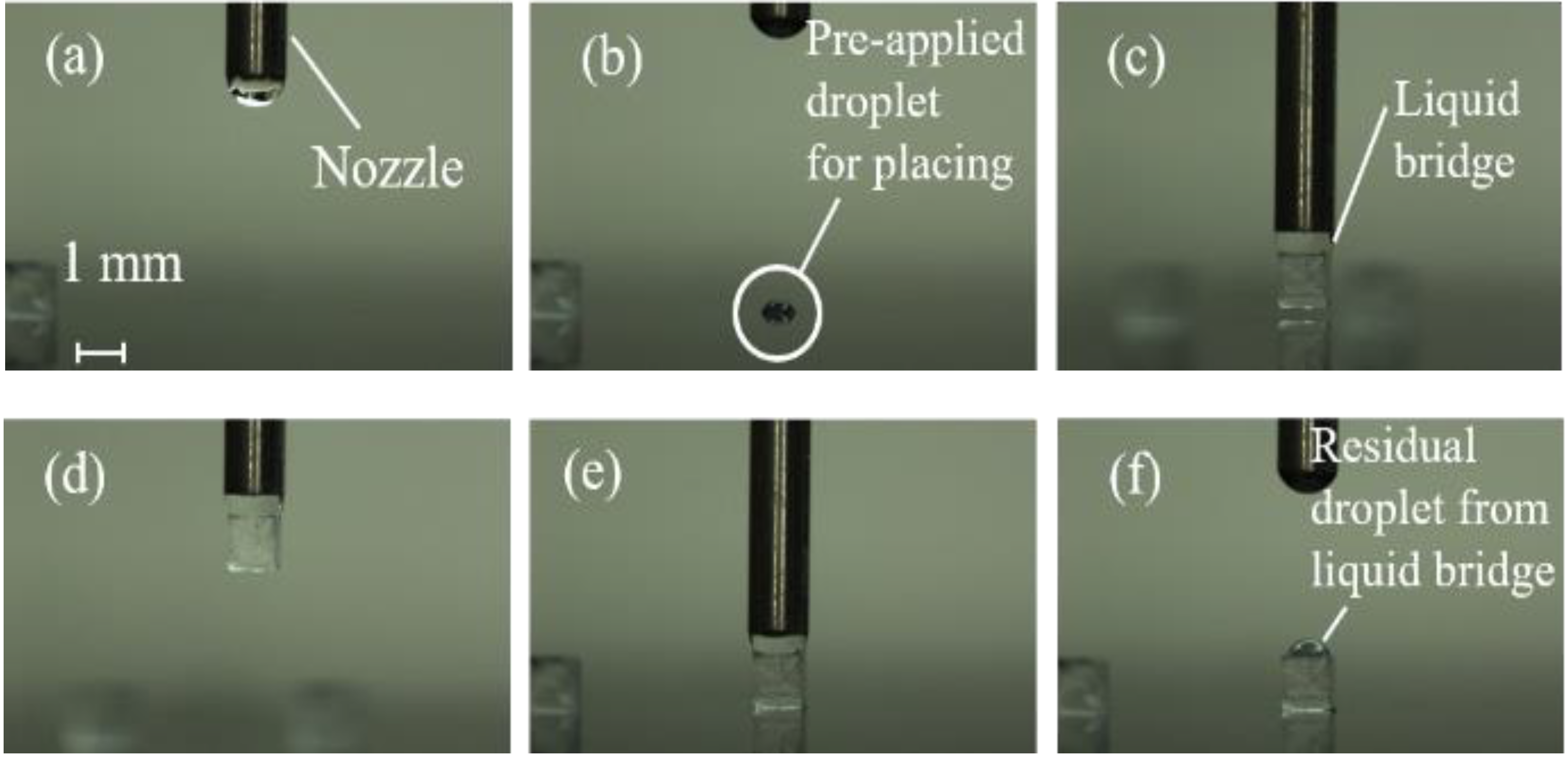
Figure 7 shows the sequence of pick-and-place operations under the condition of (C3) for
h2 of 50 μm.
In
Table 4, the success rates and positioning errors for
h2 = 0, 50, 70, 100, and 120 μm are compared. From
Table 4 and
Figure 7, the newly developed vision feedback system confirmed that the gripper could automatically pick-and-place objects without solid contact.
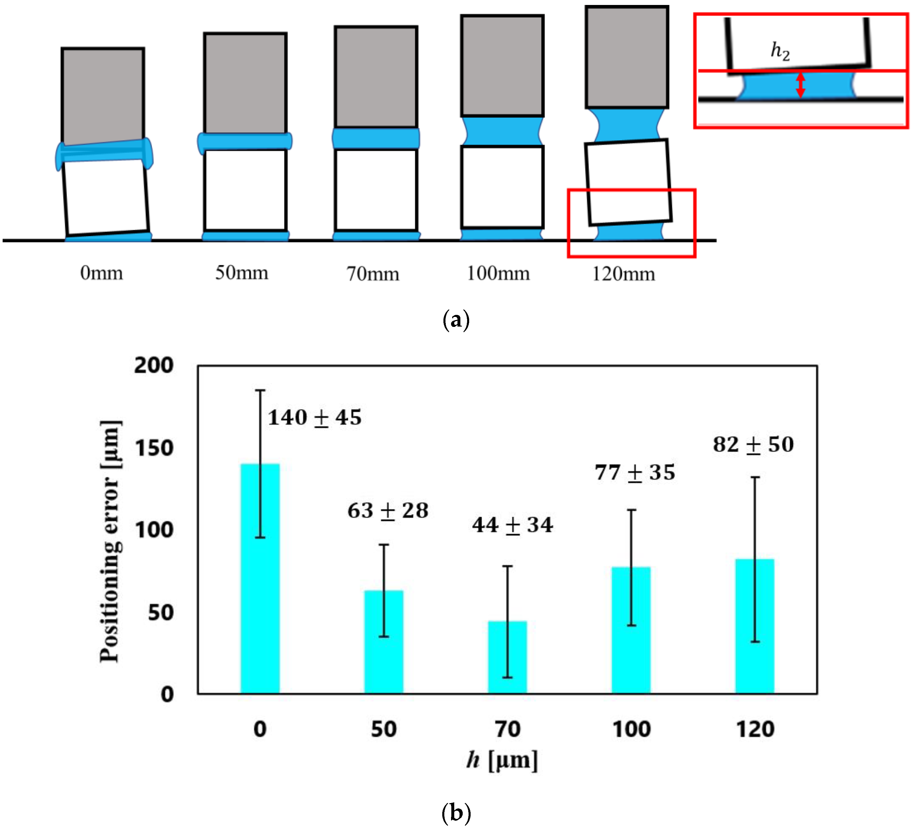
Figure 8 shows the relationship between the positioning errors and
h2 under the condition (C3).
The smallest value of the positioning error was 44 ± 34 μm with h2 = 70 μm (the ratios to the cube side were 4.4 ± 3.4%), although the error with h2 = 50 μm had almost the same value.
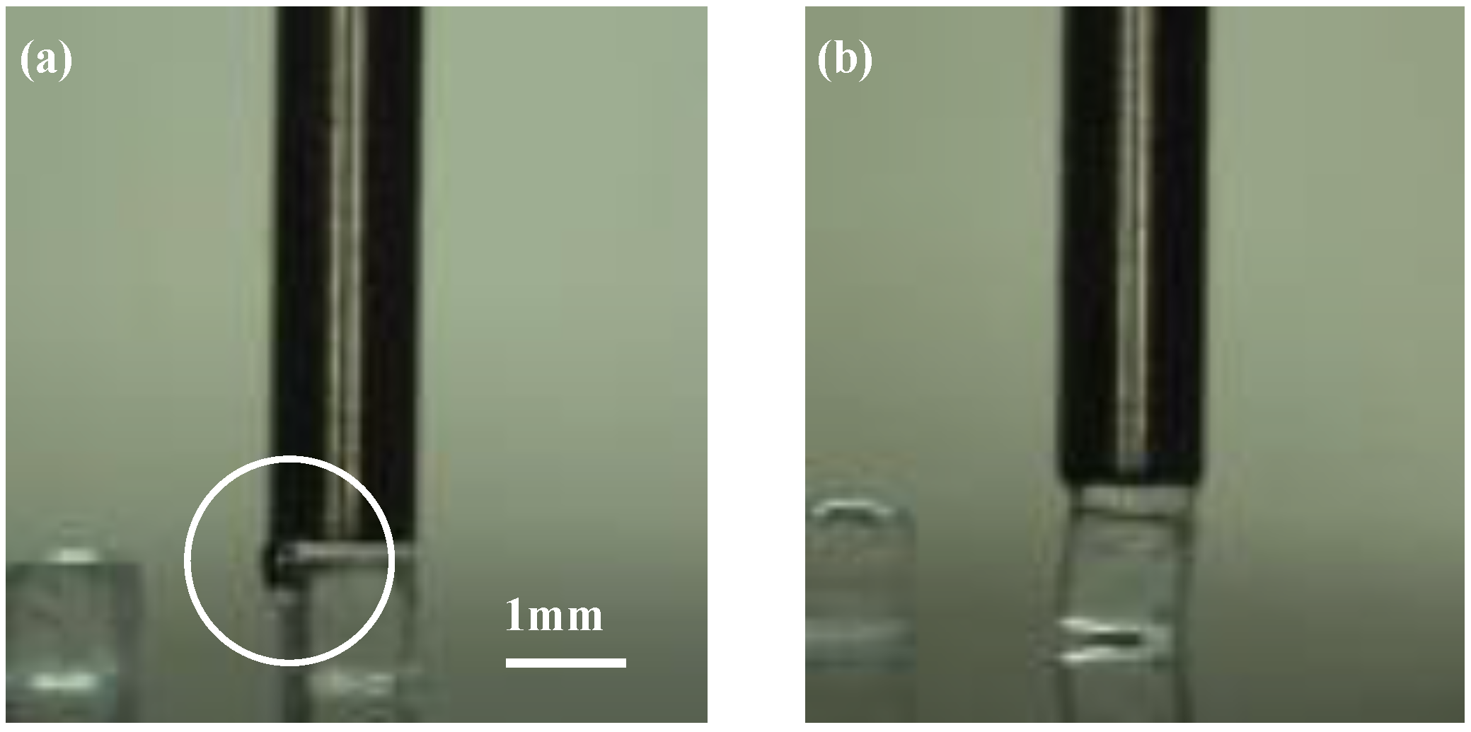
Figure 9 shows the typical examples for a large positioning error. The water spread to the sides of the object when
h2 was too small, as shown in
Figure 9a, whereas the cube was easily inclined when
h2 was too large, leading to a large positioning error, as shown in
Figure 9b.
6.2. Evaluation of Size Matching Effect
The positioning errors for each condition are compared in
Table 5. We used the result with the smallest error out of the
h2 values set for each condition.
The cube moves toward the center position of the droplet on the surface due to surface tension as a self-alignment phenomenon. If the average error is only attributed to the center position of the pre-applied droplet, the errors of (C1) and (C3) should be almost equal because the same nozzle is used for applying the droplet to the surface. For the same reason, that of (C2) and (C4) should also be almost equal. However, twice the difference between (C1) and (C3) and quadruple the difference between (C2) and (C4) can be observed from
Table 5. We supposed that the size and shape matching effects also influenced the final alignment errors [
29,
30,
31].
To examine the size matching effect, we defined the diameter of the circular nozzle as
D, the positioning error as
E, and the side length of the cube as
L. We normalized the parameters (
) by
L as follows:
We compared the results in
Table 5 using these parameters to verify a suitable size of circular shaped nozzle for each object, as shown in
Figure 10.
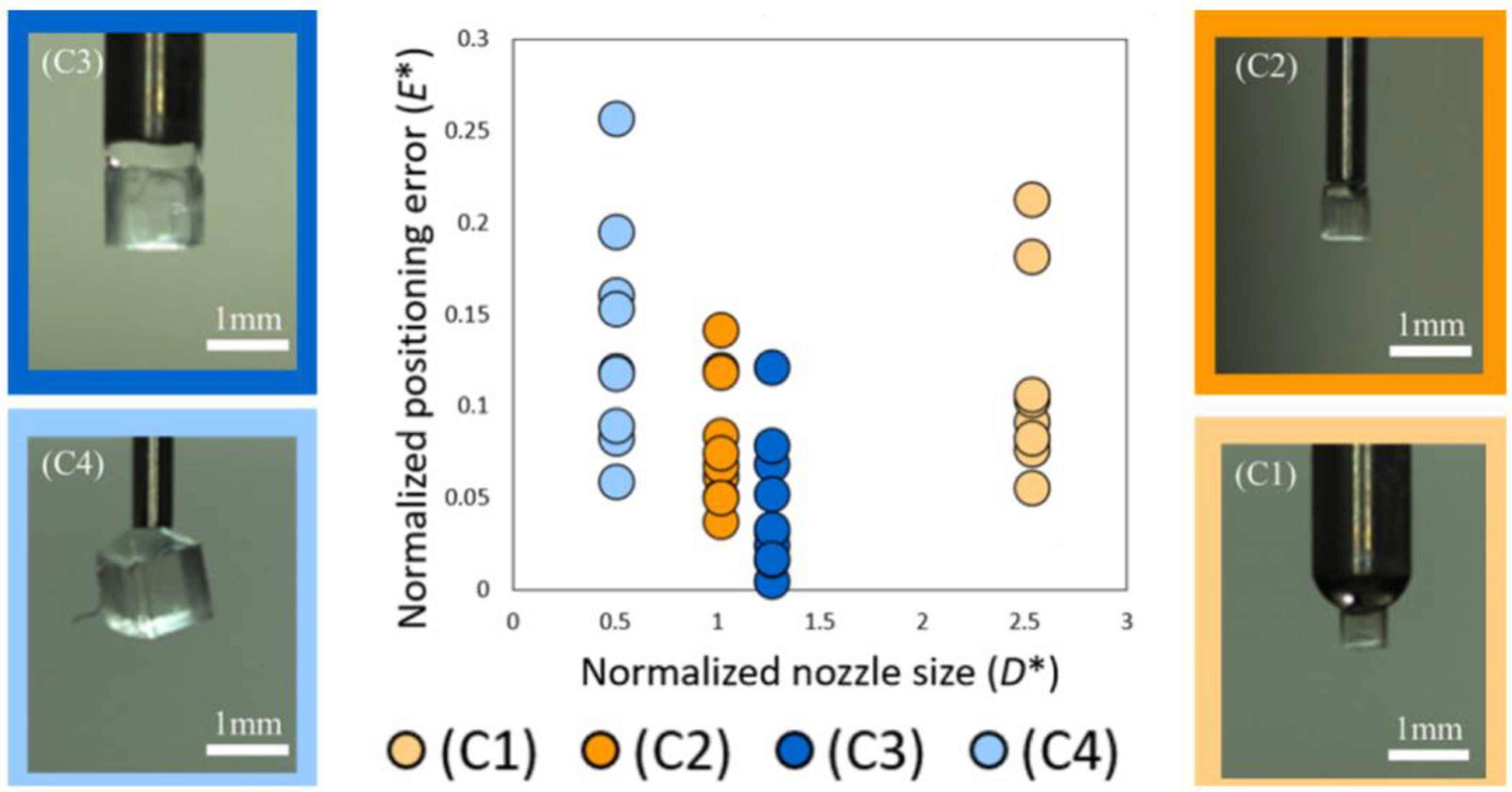
As shown in
Figure 10, the closer
D* is to 1, the smaller the positioning error becomes. When the nozzle diameter was approximately twice as large as the object as in condition (C1), the distribution of the final alignment position was larger than those of (C2) and (C3). When the nozzle diameter was approximately half of the object, as in condition (C4), the object was often tilted during pick-up, as shown in the photograph of
Figure 10 (C4). That is the main reason why (C4) obtained the largest distribution among the four conditions.
6.3. Attitude Control Using Shape Matching Effect
We considered that the attitude angle of the picked-up object could be controlled by matching the shape of the nozzle to the picked object.
To examine the shape matching effect [
30,
31], we conducted the pick-and-place experiment as in condition (S) in
Table 4 with a square-shaped nozzle and side length of 1 mm for the 1-mm cube.
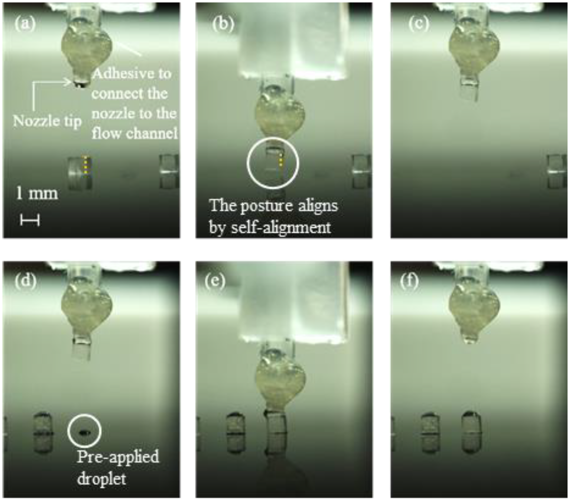
Figure 11 shows a sequential photograph of the pick-and-place operation.
From
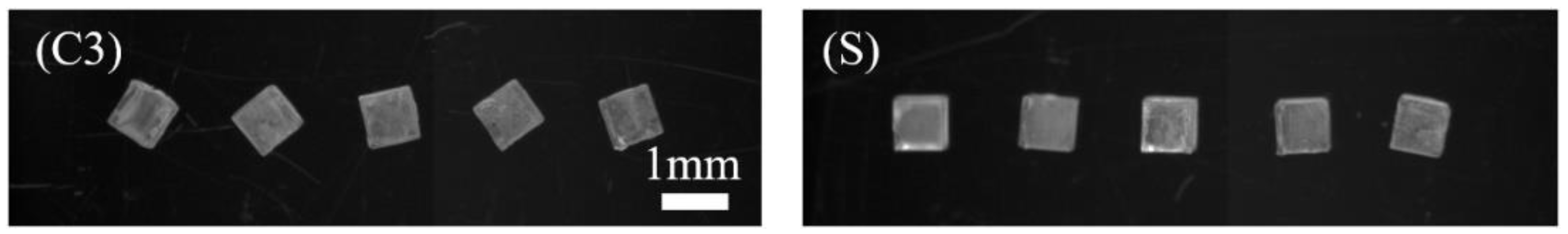
Figure 11a,b, the object changed its attitude angle for aligning the nozzle shape; we verified that the shape matching effect is useful for controlling the attitude of the sample. The movement of the object is illustrated in
Figure 12.
We compared the experimental results with condition (C3) using a circular nozzle to conduct a pick-and-place of the same cubed object. The positioning error and the attitude angle of the object after placement are shown in
Table 6, and the image of the object after placement is shown in
Figure 13.
As no target angle was set in these experiments, we focused on the standard deviations (SDs) to discuss the experimental results of the accuracy of the attitude angle.
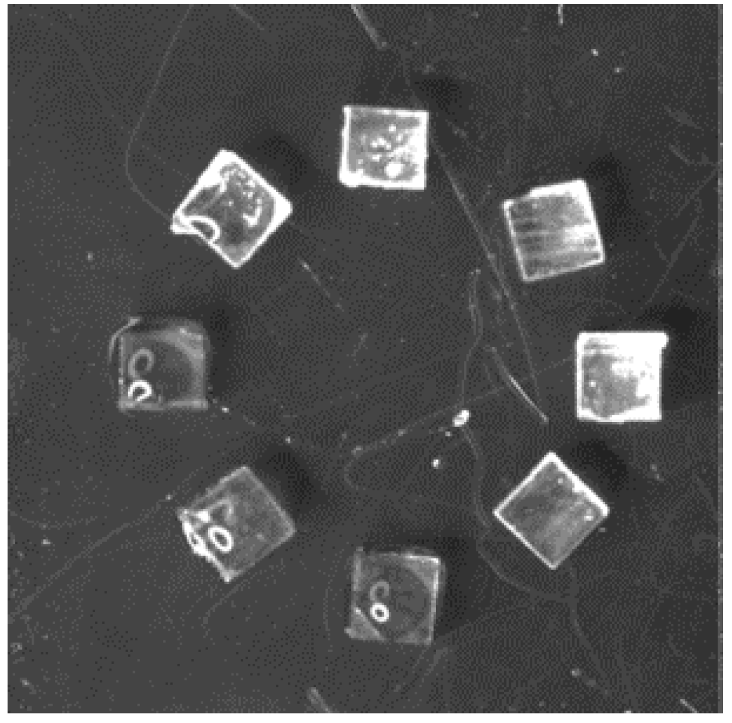
Table 6 shows that the SD of the attitude angle under condition (S) was smaller than condition (C3). Using this nozzle and a rotational stage, we could set the objects at various angles, as shown in
Figure 14.
7. Conclusions and Future Prospects
This paper described a newly developed vision feedback method for improving the placement accuracy for a single nozzle capillary gripper. The developed system was coded in Python using OpenCV.
In the experiment, we automatically picked-and-placed the cubes without any solid contact, and the success rate was 99% (129 out of 130 samples). For the cubes with 1- and 0.5-mm sides, the minimum positioning error ± SD of each size was 44 ± 34 μm and 39 ± 18 μm, respectively; the ratios of the positioning errors to the lengths of the objects were 4.4 ± 3.4% and 7.8 ± 3.6%, respectively. We also verified that the size matching effect worked reasonably; the average positioning error minimized when the size of the nozzle was nearly equal to the side of the cube.
In addition, using a square-shaped nozzle with the same shape of the cube, we succeeded in controlling the attitude; the SD of the attitude angle was reduced from a random value to 7.4°.
To reduce the positioning errors, our future plans are as follows. We plan to evaluate the relationship between the surface shape and properties of the objects as well as the radius and arrangement pattern of the droplets, for effectively applying the self-alignment phenomena. Further work will study the accuracy of contour detection in the vision feedback system. The impact of lighting on positioning will also be studied in the future, for example, the effects of droplet size and color and diffraction and refraction of lighting. In addition, the investigation of the release condition is a significant subject from both theoretical and experimental approaches.
Moreover, we wish to take on the challenge of developing a pick-and-place mechanism for smaller complex-shaped objects of less than 200 µm, such as micro-LEDs, helical-shaped coils, thin wires, gears, soft contact lenses, fragile gels, and biomedical cells with the capillary grippers to cultivate the manipulation of heterogeneous and complex-shaped micro-objects in flexible electronics, micro-electro-mechanical systems (MEMS), soft robotics, soft matter, and biomedical fields. In the microminiaturization of an object, we consider the limitations to be determined as follows: the smallest possible droplet size, the sharpest nozzle, the effect of droplet evaporation, and the piezoelectric control of droplet volume.
Author Contributions
Conceptualization, T.I.; methodology, T.I., E.F. and K.T.; software, T.I.; validation, T.I., E.F., K.T. and O.F.; formal analysis, T.I., K.T. and E.F.; investigation, T.I., E.F., K.T., Y.N., N.W. and O.F.; resources, O.F.; data curation, T.I., E.F. and O.F.; writing—original draft preparation, T.I., E.F. and O.F.; writing—review and editing, E.F., N.W. and O.F.; visualization, T.I. and E.F.; supervision, Y.N. and O.F.; project administration, O.F.; funding acquisition, O.F. All authors have read and agreed to the published version of the manuscript.
Funding
This research was funded by the Grant-in-Aid for Scientific Research (C) [16K06178], Yokohama Academic Foundation, Yokohama National University Publication Subsidy.
Conflicts of Interest
The authors declare no conflict of interest.
References
- Templier, F. GaN-based emissive microdisplays: A very promising technology for compact, ultra-high brightness display systems. J. Soc. Inf. Display 2016, 24, 669–675. [Google Scholar] [CrossRef]
- Barwicz, T.; Taira, Y.; Lichoulas, T.W.; Boyer, N.; Martin, Y.; Numata, H.; Nah, J.-W.; Takenobu, S.; Janta-Polczynski, A.; Kimbrell, E.L.; et al. A Novel Approach to Photonic Packaging Leveraging Existing High-Throughput Microelectronic Facilities. IEEE J. Sel. Top. Quantum Electron. 2016, 22, 455–466. [Google Scholar] [CrossRef]
- Henly, F.J. Combining engineered epi growth substrate materials with novel test and mass-transfer equipment to enable MicroLED mass-production. SID 2018, 49, 688–691. [Google Scholar] [CrossRef]
- Feng, X.; Meitl, M.; Bowen, A.; Huang, Y.; Nuzzo, R.; Rogers, J. Competing fracture in kinetically controlled transfer printing. Langmuir 2007, 23, 12555–12560. [Google Scholar] [CrossRef]
- Carlson, A.; Bowen, A.M.; Huang, Y.; Nuzzo, R.G.; Rogers, J.A. Transfer Printing Techniques for Materials Assembly and Micro/Nanodevice Fabrication. Adv. Mater. 2012, 24, 5284–5318. [Google Scholar] [CrossRef]
- Jinno, M.; Iordachita, I. Microgripper using flexible wire hinge for robotic intraocular snake. In Proceedings of the IEEE ICRA2022, Philadelphia, PA, USA, 23–27 May 2022; pp. 6218–6224. [Google Scholar]
- Eisenhaure, J.D.; Rhee, S.I.; Al-Okaily, A.M.; Carlson, A.; Ferreira, P.M.; Kim, S. The Use of Shape Memory Polymers for MEMS Assembly. J. Microelectromechanical Syst. 2016, 25, 69–77. [Google Scholar] [CrossRef]
- Xia, Y.; He, Y.; Zhang, F.; Liu, Y.; Leng, J. A review of shape memory polymers and composites: Mechanisms, materials, and applications. Adv. Mater. 2020, 33, 202000713. [Google Scholar] [CrossRef]
- Amit, R.; Abadi, A.; Kosa, G. Characterization of steady streaming for a particle manipulation system. Biomed. Microdevices 2016, 18, 39. [Google Scholar] [CrossRef]
- Fuchiwaki, O.; Tanaka, Y.; Notsu, H.; Hyakutake, T. Multi-axial non-contact in situ micromanipulation by steady streaming around two oscillating cylinders on holonomic miniature robots. Microfluid. Nanofluidics 2018, 22, 80. [Google Scholar] [CrossRef] [Green Version]
- Benhal, P.; Chase, J.G.; Gaynor, P.; Oback, B.; Wang, W. AC electric field induced dipole-based on-chip 3D cell rotation. Lab Chip 2014, 14, 2717–2727. [Google Scholar] [CrossRef]
- Berns, M.W. Laser scissors and tweezers to study chromosomes: A review. Front Bioeng. Biotechnol. 2020, 8, 721. [Google Scholar] [CrossRef]
- Choudhary, D.; Mossa, A.; Jadhav, M.; Cecconi, C. Bio-molecular applications of recent developments in optical tweezers. Biomolecules 2019, 9, 23. [Google Scholar] [CrossRef] [Green Version]
- Lee, V.; James, N.M.; Waitukaitis, S.R.; Jaeger, H.M. Collisional charging of individual submillimeter particles: Using ultrasonic levitation to initiate and track charge transfer. Phys. Rev. Mater. 2018, 2, 035602. [Google Scholar] [CrossRef]
- Shi, Q.; Di, W.; Dong, D.; Yap, L.W.; Li, L.; Zang, D.; Cheng, W. A general approach to free-standing nanoassemblies via acoustic levitation self-assembly. ACS Nano 2019, 13, 5243–5250. [Google Scholar] [CrossRef]
- Mastrangeli, M.; Abbasi, S.; Varel, Ç.; Hoof, C.V.; Celis, C.P.; Böhringer, K.F. Self-assembly from milli to nanoscales: Methods and applications. J. Micromech. Microeng. 2009, 19, 083001. [Google Scholar] [CrossRef]
- Najib, A.M.; Abdullah, M.Z.; Saad, A.A.; Samsudin, Z.; Che Ani, F. Numerical simulation of self-alignment of chip resistor components for different silver content during reflow soldering. Microelectron. Reliab. 2017, 79, 69–78. [Google Scholar] [CrossRef]
- Uran, S.; Šafaric, R.; Bratina, B. Reliable and accurate release of micro-sized objects with a gripper that uses the capillary-force method. Micromachines 2017, 8, 182. [Google Scholar] [CrossRef] [Green Version]
- Fuchiwaki, O.; Kumagai, K. Development of wet tweezers based on capillary force for complex-shaped and heterogeneous micro-assembly. In Proceedings of the 2013 IEEE/RSJ International Conference on Intelligent Robots and Systems, Tokyo, Japan, 3–7 November 2013; pp. 1003–1009. [Google Scholar]
- Kato, Y.; Mizuno, T.; Takagi, H.; Ishino, Y.; Takasaki, M. Experimental study on microassembly by using liquid surface tension. SICE J. Control. Meas. Syst. Integr. 2010, 3, 309–314. [Google Scholar] [CrossRef]
- Hagiwara, W.; Ito, T.; Tanaka, K.; Tokui, R.; Fuchiwaki, O. Capillary force gripper for complex-shaped micro-objects with fast droplet forming by on-off control of a piston slider. IEEE Robot Autom. Lett. 2019, 4, 3695–3702. [Google Scholar] [CrossRef]
- Tanaka, K.; Ito, T.; Nishiyama, Y.; Fukuchi, E.; Fuchiwaki, O. Double-nozzle capillary force gripper for cubical, triangular prismatic, and helical 1-mm-Sized-Objects. IEEE Robot Autom. Lett. 2022, 7, 1324–1331. [Google Scholar] [CrossRef]
- Lambert, P. Capillary Forces in Microassembly; Springer: New York, NY, USA, 2007. [Google Scholar]
- Tselishchev, Y.G.; Val’tsifer, V.A. Influence of the type of contact between particles joined by a liquid bridge on the capillary cohesive forces. Colloid J. 2003, 65, 385–389. [Google Scholar] [CrossRef]
- Itaki, T.; Taira, Y.; Kuwamori, N.; Maebayashi, T.; Takeshima, S.; Toya, K. Automated collection of single species of microfossils using a deep learning–micromanipulator system. Prog. Earth Planet. Sci. 2020, 7, 19. [Google Scholar] [CrossRef]
- Shoji, D.; Noguchi, R.; Otsuki, S.; Hino, H. Classification of volcanic ash particles using a convolutional neural network and probability. Sci. Rep. 2018, 8, 8111. [Google Scholar] [CrossRef]
- Panarello, A.P.; Seavey, C.E.; Doshi, M.; Dickerson, A.K.; Kean, T.J.; Willenberg, B.J. Transforming capillary alginate gel into new 3D-printing biomaterial inks. Gels 2022, 8, 376. [Google Scholar] [CrossRef]
- Ji, X.; Liu, X.; Cacucciolo, V.; Imboden, M.; Civet, Y.; Haitami, A.E.; Cantin, S.; Perriard, Y.; Shea, H. An autonomous untethered fast soft robotic insect driven by low-voltage dielectric elastomer actuators. Sci. Robot 2019, 4, eaaz6451. [Google Scholar]
- Mastrangeli, M.; Ruythooren, W.; Celis, J.; Van Hoof, C. Challenges for capillary self-assembly of microsystems. IEEE Trans. Compon. Packaging Manuf. Technol. 2011, 1, 133–149. [Google Scholar] [CrossRef]
- Stauth, S.A.; Parviz, B. Self-assembled single-crystal silicon circuits on plastic. Proc. Natl. Acad. Sci. USA 2006, 103, 13922–13927. [Google Scholar] [CrossRef] [Green Version]
- Takagi, S.; Shimada, T.; Ishida, Y.; Fujimura, T.; Masui, D.; Tachibana, H.; Eguchi, M.; Inoue, H. Size-matching effect on inorganic nanosheets: Control of distance, alignment, and orientation of molecular adsorption as a bottom-up methodology for nanomaterials. Langmuir 2013, 29, 2108–2119. [Google Scholar] [CrossRef]
Figure 1.
Working area of the pick-and-place of 1-mm cubes.
Figure 1.
Working area of the pick-and-place of 1-mm cubes.
Figure 2.
Capillary bridge between two parallel planes.
Figure 2.
Capillary bridge between two parallel planes.
Figure 3.
Mechanism of water filling till the tip of the channel by capillary action.
Figure 3.
Mechanism of water filling till the tip of the channel by capillary action.
Figure 4.
Principle of droplet formation.
Figure 4.
Principle of droplet formation.
Figure 5.
Experimental setup for the automatic pick-and-place.
Figure 5.
Experimental setup for the automatic pick-and-place.
Figure 6.
Process of the vision feedback system in placing: (a) the capture image, (b) the image with the Sobel filter, (c) the binarized image, (d) detecting contours, (e) calculating the distance l1, (f) the definition of h2, and (g) the definition of l2.
Figure 6.
Process of the vision feedback system in placing: (a) the capture image, (b) the image with the Sobel filter, (c) the binarized image, (d) detecting contours, (e) calculating the distance l1, (f) the definition of h2, and (g) the definition of l2.
Figure 7.
Sequential photograph of the pick-and-place experiment under (C3) for h2 = 50 μm: (a) droplet discharge from the nozzle, (b) application of the droplet by stamping the nozzle to the surface, (c) forming the liquid bridge between the nozzle and top surface of the cube, (d) picking up the cube, (e) placing the cube on the droplet on the substrate, and (f) releasing the cube by moving up the gripper.
Figure 8.
Relationship between the positioning errors and h2 under (C3). (a) Typical schematic diagram for each h2, (b) plots of positioning errors vs. h2.
Figure 8.
Relationship between the positioning errors and h2 under (C3). (a) Typical schematic diagram for each h2, (b) plots of positioning errors vs. h2.
Figure 9.
Example of a large positioning error: (a) h2 = 0 μm; (b) h2 = 100 μm.
Figure 9.
Example of a large positioning error: (a) h2 = 0 μm; (b) h2 = 100 μm.
Figure 10.
Plots of nozzle size D* vs. positioning error E*.
Figure 10.
Plots of nozzle size D* vs. positioning error E*.
Figure 11.
Sequential photograph of the pick-and-place of a 1-mm cube by the square nozzle: (a) droplet discharge from the nozzle, (b) forming the liquid bridge between the gripper and cube with a self-alignment of the attitude, (c) picking up the cube, (d) positioning the nozzle just above the pre-applied droplet, (e) placing the sample on the droplet on the substrate, and (f) releasing the sample by moving the gripper up.
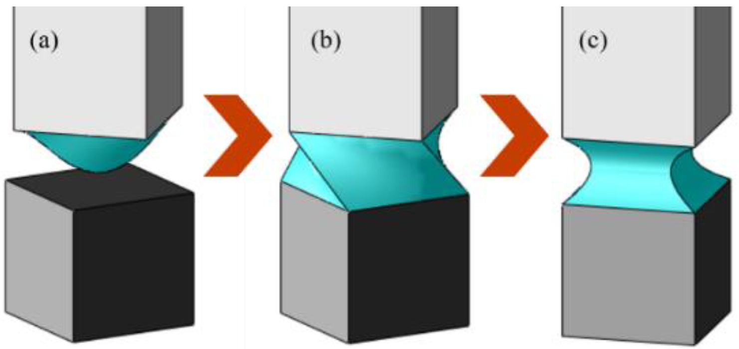
Figure 12.
Shape matching sequence between same-sized square nozzle and cube: (a) droplet discharge from the square nozzle, (b) just before the liquid spreading and making the liquid bridge between two surfaces, and (c) liquid bridge deformed into a symmetrical shape such that the surface energy of the liquid bridge is minimized.
Figure 13.
Arrangement of 1-mm cubes under conditions (C3) and (S).
Figure 13.
Arrangement of 1-mm cubes under conditions (C3) and (S).
Figure 14.
Circular arrangements of 1-mm cubes at various angles.
Figure 14.
Circular arrangements of 1-mm cubes at various angles.
Table 1.
Specifications of micro-objects.
Table 1.
Specifications of micro-objects.
| Name | 1 mm Cube | 0.5 mm Cube |
|---|
| Image | ![Micromachines 13 01270 i001]() | ![Micromachines 13 01270 i002]() |
| Material | Acrylic |
| Geometric parameters | Depth: 1 mm
Width: 1 mm
Height: 1 mm | Depth: 0.5 mm
Width: 0.5 mm
Height: 0.5 mm |
| Gravity force | 12 μN | 1.5 μN |
Table 2.
Experimental condition and the parameters.
Table 3.
Targeted values of .
Table 3.
Targeted values of .
| Condition | (C1) | (C2) | (C3) | (C4) | (S) |
|---|
| Cube size | 0.5 mm | 1 mm |
| Nozzle shape | Circle | Square |
| Nozzle size (mm) | 1.27 | 0.51 | 1.27 | 0.51 | 1 × 1 |
| Diameter |
| (μm) | 10
25
50 | 10
25
50 | 0
50
70
100
120 | 25
50 | 70 |
Table 4.
Comparison of success rate and position errors.
Table 4.
Comparison of success rate and position errors.
| 0 | 50 | 70 | 100 | 120 |
|---|
| Success rate | Pick-up (%) | 100 | 100 | 100 | 100 | 100 |
| Place-down (%) | 100 | 90 | 100 | 100 | 100 |
| Positioning error | Average (µm) | 140 | 63 | 44 | 77 | 82 |
| Standard deviation (µm) | 45 | 28 | 34 | 35 | 50 |
Table 5.
Comparison of the positioning errors for conditions (C1), (C2), (C3), and (C4).
Table 5.
Comparison of the positioning errors for conditions (C1), (C2), (C3), and (C4).
| Condition | (C1) | (C2) | (C3) | (C4) |
|---|
| Ratio of nozzle size to object size | 254 (%) | 102 (%) | 127 (%) | 51 (%) |
| h2 | 25 (μm) | 25 (μm) | 70 (μm) | 25 (μm) |
| Average error | 80 (μm) | 40 (μm) | 44 (μm) | 154 (μm) |
| Standard deviation | 53 (μm) | 17 (μm) | 34 (μm) | 77 (μm) |
| Ratio of error to object size | 16 ± 10.6 (%) | 8.0 ± 3.4 (%) | 4.4 ± 3.4 (%) | 15.4 ± 7.7 (%) |
Table 6.
Comparison of the positioning errors and attitude angles for conditions (C3) and (S).
Table 6.
Comparison of the positioning errors and attitude angles for conditions (C3) and (S).
| Condition | (C3) | (S) |
|---|
| Positioning error | Average | 44 (μm) | 99 (μm) |
| Standard deviation | 34 (μm) | 57 (μm) |
Attitude
angle | Average | −3.0 (deg.) | −2.8 (deg.) |
| Standard deviation | 26.9 (deg.) | 7.4 (deg.) |
| Publisher’s Note: MDPI stays neutral with regard to jurisdictional claims in published maps and institutional affiliations. |
© 2022 by the authors. Licensee MDPI, Basel, Switzerland. This article is an open access article distributed under the terms and conditions of the Creative Commons Attribution (CC BY) license (https://creativecommons.org/licenses/by/4.0/).


