1. Introduction
Micro-manufacturing processes have been used extensively in the aerospace, biomedical and defense industries. Presently, photolithography-based manufacturing techniques are used for selective materials such as Ni, Cu, Si and polymers to produce high aspect-ratio components. Micro-machining processes like micro-milling are able to generate three-dimensional surfaces in ceramics, metals and polymers [
1,
2,
3,
4,
5,
6]. Micro-machining is becoming popular because of its ability to produce three-dimensional parts of different sizes varying from a few micrometers to a few millimeters across various materials [
7]. The micro-milling, micro-EDM, micro-grinding and micro-grooving processes are part of the micro-machining process.
Micro-milling is a micro-cutting process which is used for the fabrication of micro-and meso-scale components and devices. It can also be said that it is a milling operation at the micro-scale. However, there are vital drawbacks of the micro-milling process, particularly when machining hard materials having a hardness of 7.25–8.43 GPa and sintered ceramics having a hardness of 12.75–14.71 GPa. These drawbacks are due to the small size of the cutting tools, low flexural stiffness and strength compared to conventional-scale tools due to low material removal rates, rapid tool wear/failure and poor part feature accuracy, especially when cutting hard materials occurs [
8,
9,
10].
Figure 1 shows a two-flute micro-end mill cutting tool with important dimensions [
11]. The low flexural stiffness of these tools results in catastrophic failure because of the bending stresses generated by the cutting forces.
To prevent tool failure, a few methods have been proposed in previous research work. The first method is using cutting fluids to dissipate heat and provide lubrication. This facilitates the minimization of friction at the tool–workpiece interface and, in turn, reduces tool wear. However, this method is not very successful in micro-milling machining. The main reason is that the application of the cutting fluid to the cutting zone and the tool–workpiece interface is very difficult because of high cutting speeds and the small size of the contact zone [
12]. The second method is the use of coatings on the micro-tool to reduce wear. This enhances tool life [
1]. However, very little has been reported in tool-wear studies of coated micro-tools. The aim of the present work is to study the wear of micro-machining. Therefore, later in the introduction section, a brief description of wear is presented. There are several types of wear phenomena occurring in the field of mechanics, such as adhesive, abrasive, fatigue, corrosive and fretting wear as well as erosive wear by solid particles, fluids and cavitation and electric arc–induced and delamination wear. Wear of non-lubricated metal pairs sliding in a dusty environment may be termed as dry sliding wear and abrasive wear. The classification of wear processes is based on the type of wearing contacts, such as single-phase and multiple-phase.
In micro-machining, smaller tools are used. Researchers have reported that low flexural stiffness and strength causes huge bending of the tool, hampering the cutting process and leading to tool failure [
5,
13,
14]. This is avoided by minimizing the cutting forces below a certain critical value in order to ensure that the uncut chip thickness remains sufficiently small. During the machining of steel, titanium, nickel alloys, etc. the maximum permissible chip thickness is on the order of or less than the cutting-edge radius [
14,
15].
In the conventional milling process, the work pieces act as isotropic and homogeneous materials, whereas in micro-milling, the smaller grains in the work piece are comparable to the size of the tool. In view of the above, the micro-milling process is very complicated [
14]. The chips, which adhere to the tool, block the path at the cutting zone, and this results in an increase in the cutting forces and leads to a catastrophic failure of the tool because of its low flexural stiffness. Moreover, the small size of the micro-milling cutters makes the tip very weak because of its low stiffness value. Diamond-coated cutters are promising because of their ability to improve tool stiffness and tool life [
16].
In micro-machining, the uncut chip thickness (h) is less than the cutting-edge radius (re) due to the negative effective rake angle (−α) influencing the ploughing effect in the work piece [
5]. Therefore, the ratio of uncut chip thickness to cutting-edge radius is an important parameter in micro-machining [
5,
8]. A sharper cutting edge is required to remove the smallest amount of undeformed chip thickness [
17].
The major limitations of the micro-milling process are unpredictable tool life and premature tool failure, deterioration of the cutting edge and tool wear leading to high friction generation [
18,
19,
20,
21,
22,
23,
24,
25,
26,
27,
28,
29]. It has been reported that coated micro-cutting tools have longer tool life and improved cutting performance [
25]. Many researchers have used TiAlN-coated micro tools in cutting tests [
19,
20,
23,
24,
28,
30]. It has also been reported that CrTiAlN-coated micro-end mills provide great advantage in tool wear reduction and smooth surface finish [
31,
32]. The small size of micro-milling tools makes coating deposition difficult around the cutting edge. The desirable properties of the coatings for micro-machining tools are high hardness, toughness, chemical/erosive and abrasive wear resistance as well as dense and fine microstructure. Coating also provides smooth machined surfaces with a reduced coefficient of friction compared with uncoated tools [
33].
TiN, TiCN, TiAlN and Al
2O
3 are coatings that have been frequently used in industry. Earlier studies reveal that an increase in tool life is due to an increase in hardness, greater bonding energy of the coating elements and lower friction coefficients. Due to oxidation resistance and wear resistance at higher temperatures, TiAlN coating improved cutting performance. These properties make TiAlN an appropriate coating for cutting abrasive work pieces at high speeds [
34]. It has been found that the coating on a micro-milling cutting tool fails due to delamination, which was confirmed by the SEM images and EDS spectra of the worn tools [
35]. Delamination wear occurs due to surface layer deformation, crack nucleation and propagation of cracks parallel to the surface. Cracks finally shear the surface, resulting in long and thin wear sheets.
Earlier it was reported in the literature through the four-point bending test that thick coatings, usually more than 2 µm, delaminate from the surface of the substrate because of their high summary toughness. Along the interface of the coating and substrate, there is a difference in material properties which facilitates delamination. Finally, the coating fails due to the buckling and spalling of the delaminated portion [
36].
2. Research Objective
From the literature review, it was found that delamination in the coating of micro-milling cutting tools is confirmed only through SEM images and EDS spectra. However, coating material which is suitable for micro-milling applications and of appropriate thickness has not been reported in the literature. The delamination of coating from the substrate from the mechanics point of view has not been reported in the literature. Moreover, the factors on which delamination depend need to be examined. It was also found in the literature review that the coatings which are commonly used for micro-milling applications are titanium nitride (TiN), diamond-like carbon (DLC), aluminium titanium nitride (AlTiN) and titanium silicon nitride (TiSiN). It has been reported that the thickness of these coatings usually ranges from 2 to 4 microns [
37,
38,
39,
40,
41,
42,
43,
44,
45]. Authors have also studied various metal deposition techniques in the past 5 years and studied their performance to reduce delamination [
46,
47,
48,
49,
50,
51,
52,
53,
54,
55].
The objective of the present work is to carry out finite element analysis of commonly used coatings for micro-milling applications on high-speed steel substrates and evaluate the following.
Objective 1: to model delamination of the coating from the substrate for micro-milling applications and find out factors on which delamination depends.
Objective 2: to evaluate the performance of different coating materials for delamination and report the best coating material for micro-milling applications and their corresponding thickness.
The above mentioned objectives can be achieved by carrying out finite element analysis with high speed steel as a substrate with different coating materials of different thicknesses. In the present study, three-point bending was examined to simulate the practical conditions of the micro-milling tools during machining. The FEA results were validated using analytical results.
4. Analytical Calculation for Hertzian Normal Stress
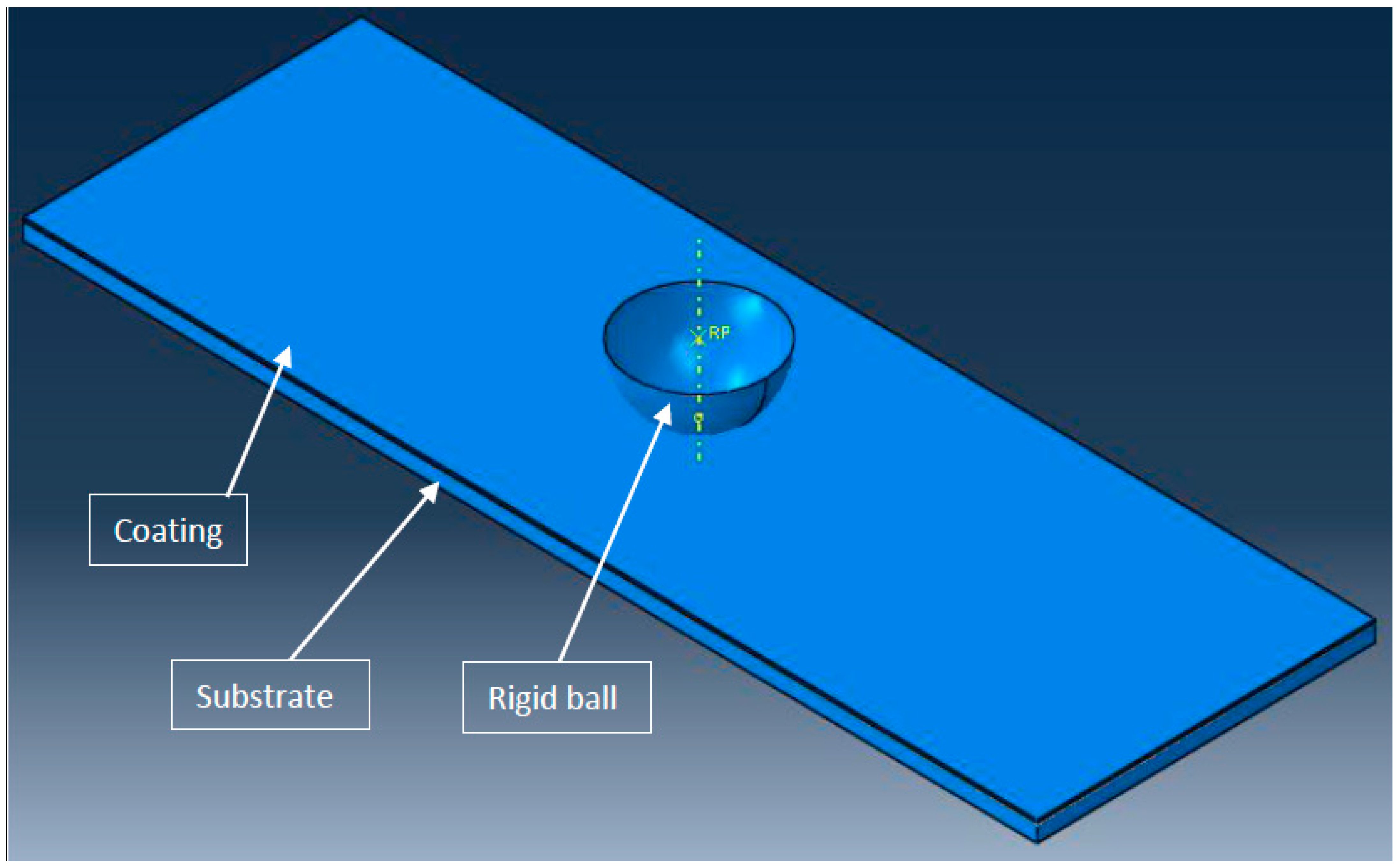
When a spherically shaped summit of radius R is brought into contact with a flat surface with a load L, as shown in
Figure 4, the surfaces deform to create the contact zone of radius a. According to Hertz’s equations for the elastic deformation of a sphere on a flat surface, the radius of the contact zone is given by
where Ec is the composite elastic modulus of the two contacting materials with the elastic modulus E
1 and E
2 and the Poisson’s ratio ν
1 and ν
2, respectively. The value of Ec is given by the relation as given below.
For this geometry, the real area of contact A is given by
The mean normal stress, pm, is given by
or,
The maximum normal stress, po, is given by
When a rigid ball of radius R = 200 µm and elastic modulus E
1 = ∞ is pressed with a normal load of 4 N against a flat plate of TiN with elastic modulus E
2 = 300 GPa and Poisson’s ratio ν = 0.22, then the maximum normal stress obtained, po, is given in
Table 5.
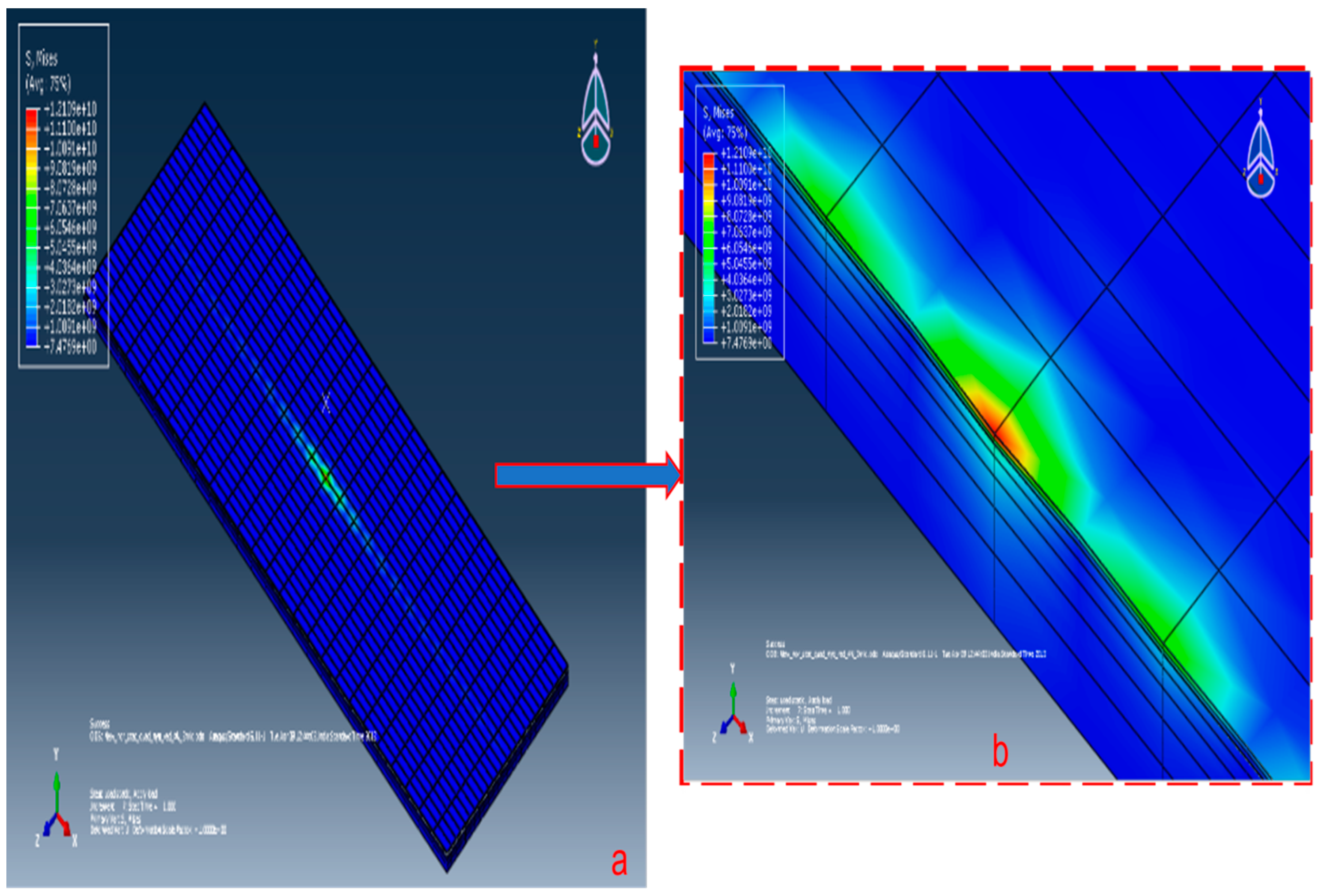
The above loading conditions of a load of 4 N through a rigid ball pressed against a flat plate of TiN is simulated in Abaqus 6.11–1. The maximum normal stress developed in FEA model was 12,109 MPa. The variation of the FEA result from the analytical result, i.e., 12,435.97 MPa, is 2.63%, which is acceptable. This confirms that the FEA model of the coating–substrate assembly is acceptable.
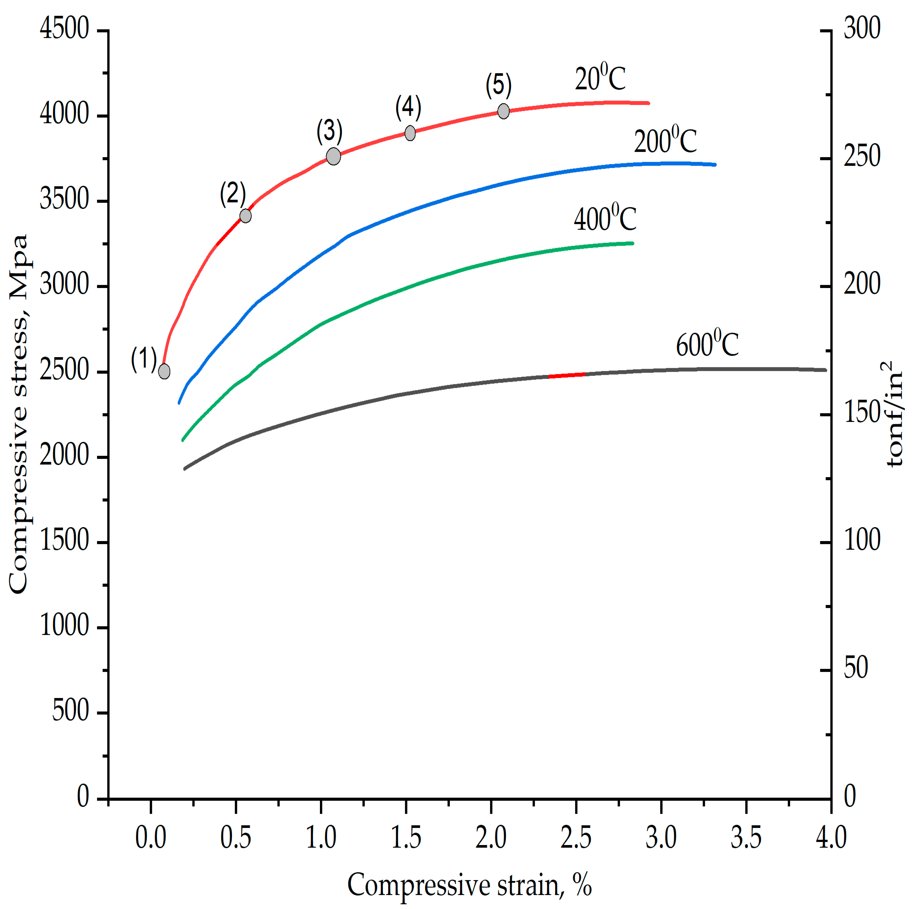
The plastic strain curve of the high-speed steel material used as a substrate is shown in
Figure 5 [
46]. With reference to
Table 6, for compressive strain, v/s compressive stress values of the HSS five data point values are extracted for the plastic behaviour of high-speed steel corresponding to a 20 °C curve, as shown in
Figure 5. This plastic behaviour data were added into the Abaqus 6.11–1 software as the plastic behaviour of the high-speed steel.
5. Results and Discussion: Performance Evaluation of Different Coating Materials in Delamination (Objective 2)
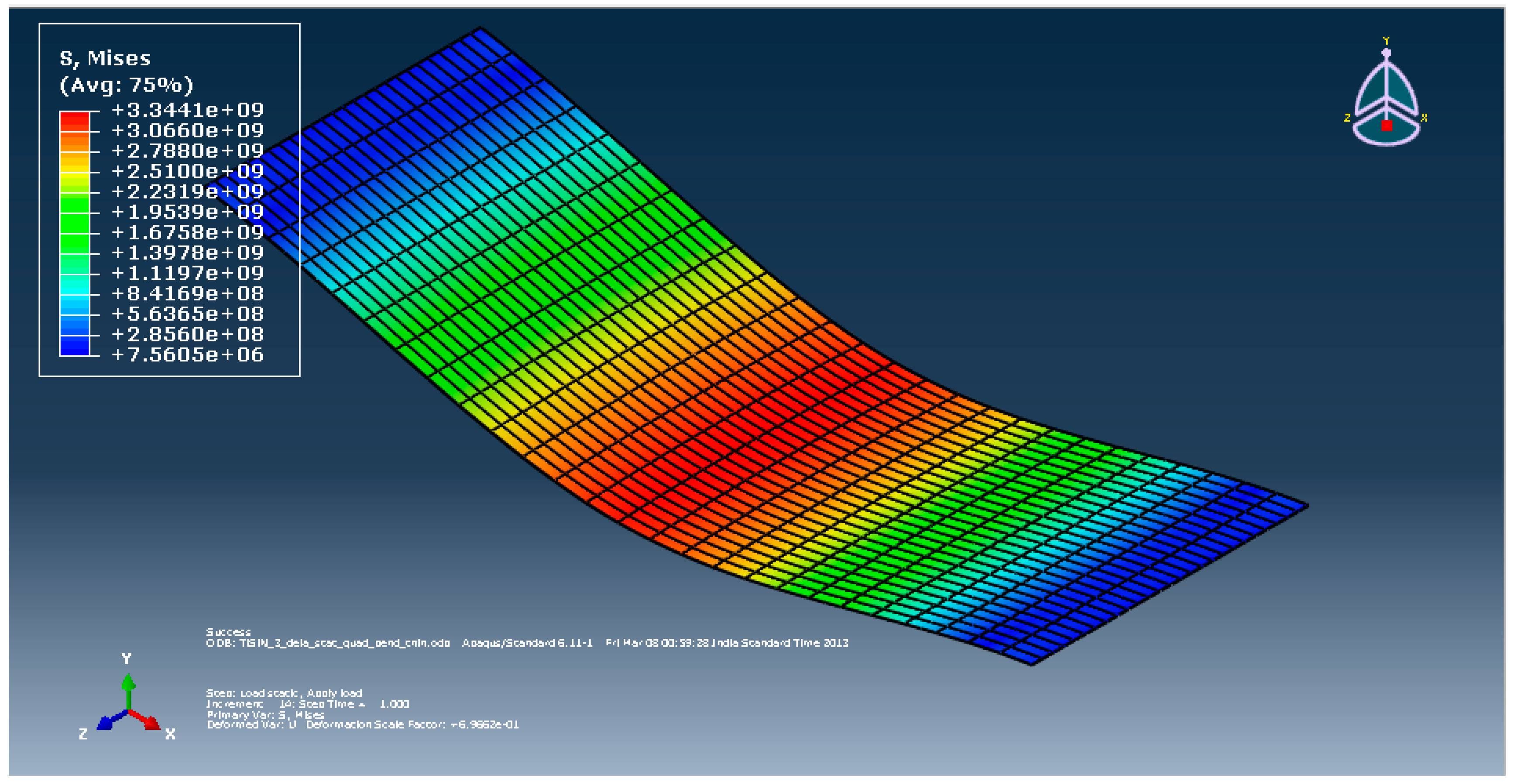
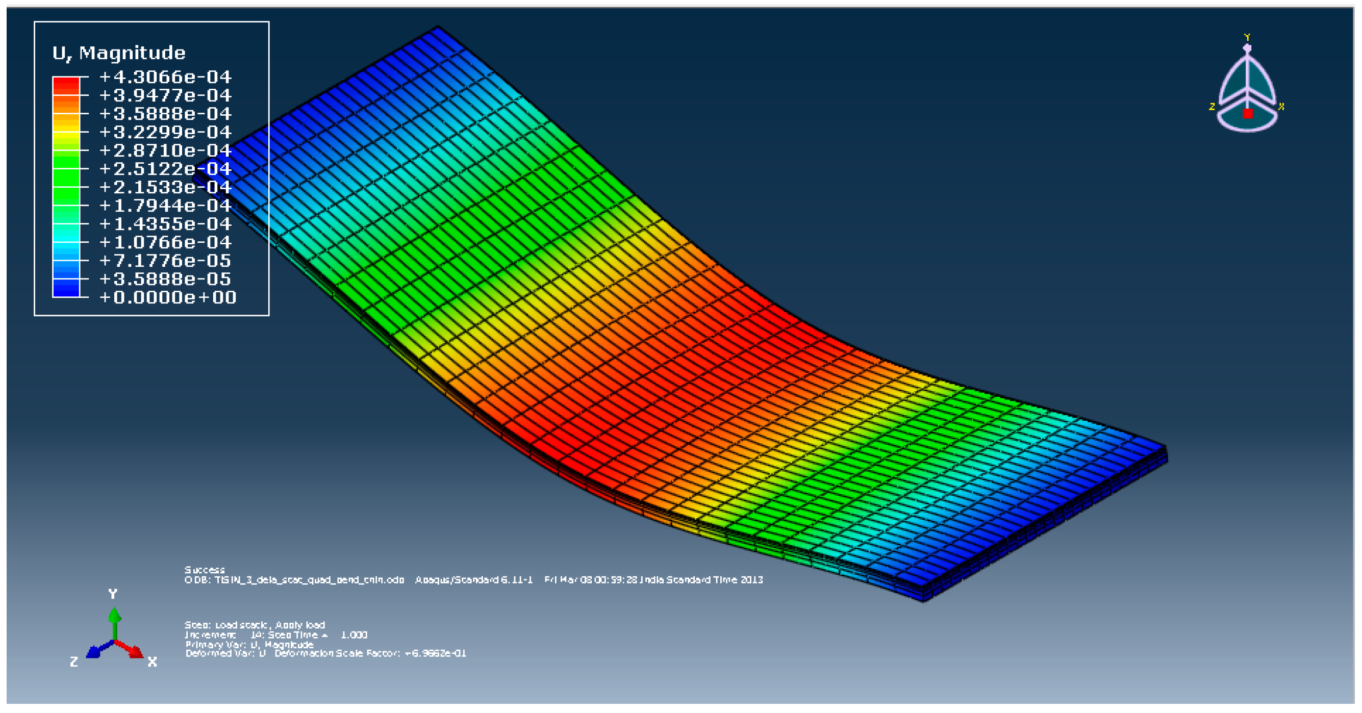
All the FEA models of the different coating–substrate assemblies with three different coating thicknesses of 2, 3 and 4 µm were run for the three-point bending load condition to evaluate the von Mises stress, the plastic equivalent strain and the deformation in the coating materials and substrate. Contour plots of the desirable outputs are given in the
Appendix A. The consolidated results of the desirable outputs of all FEA models are shown in this section.
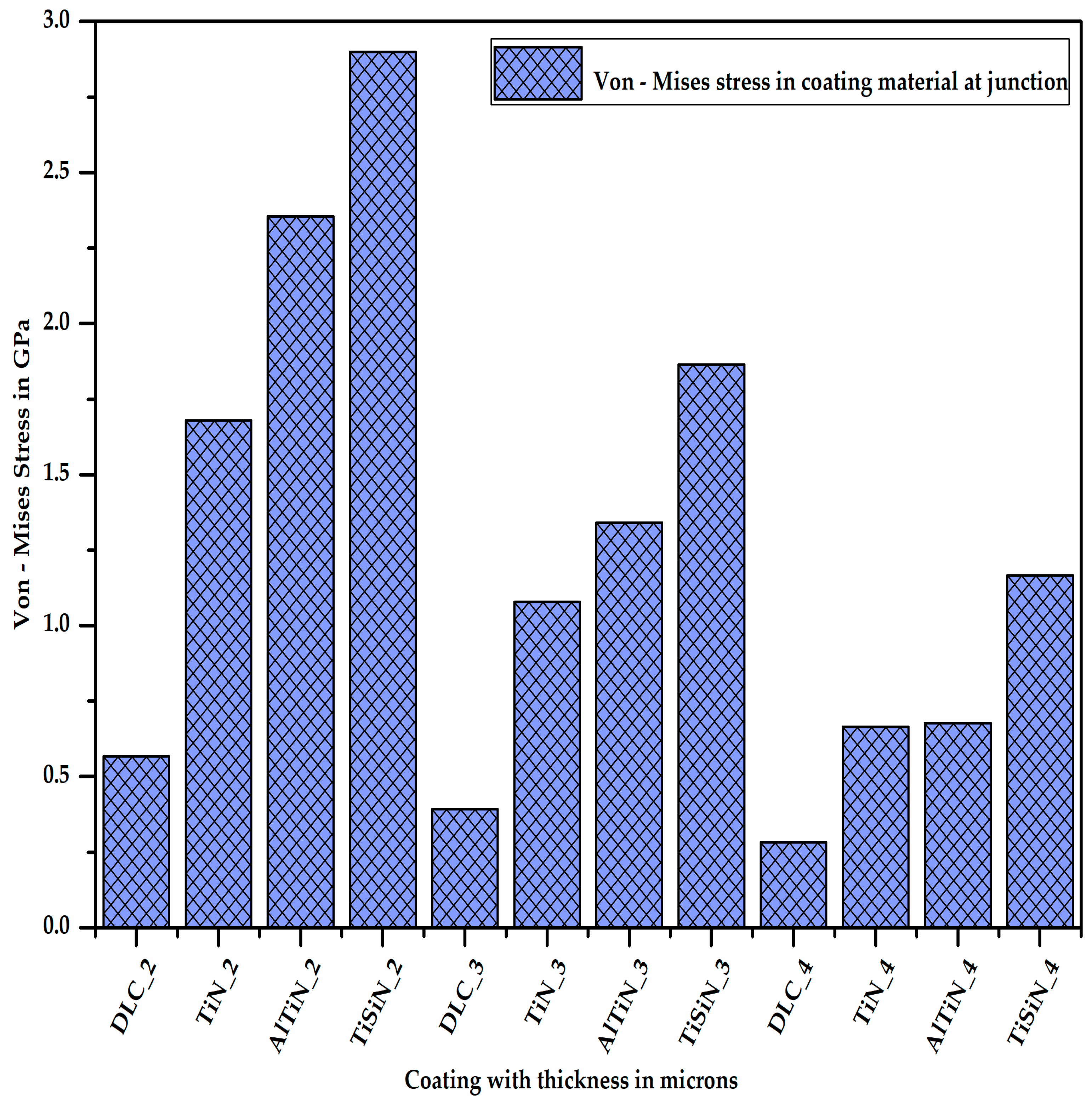
Figure 6 shows the maximum von Mises stress acting on the coating material at the junction of the coating and substrate, situated below the loading region, where AlTiN_3 represents the coating of aluminium titanium nitride material of 3 micron thickness.
It is quite clear from
Figure 6 that as the thickness of the coating material increases, the stress developed on the coating material decreases since the section modulus of the coating increases. Additionally, for a given thickness of coating material, the stress developed in the diamond-like carbon coating material is minimum (DLC_4) and that in the titanium silicon nitride coating material is maximum (TiSiN_4), which means the stress bearing capacity of the DLC coating is minimum and that of the TiSiN is maximum.
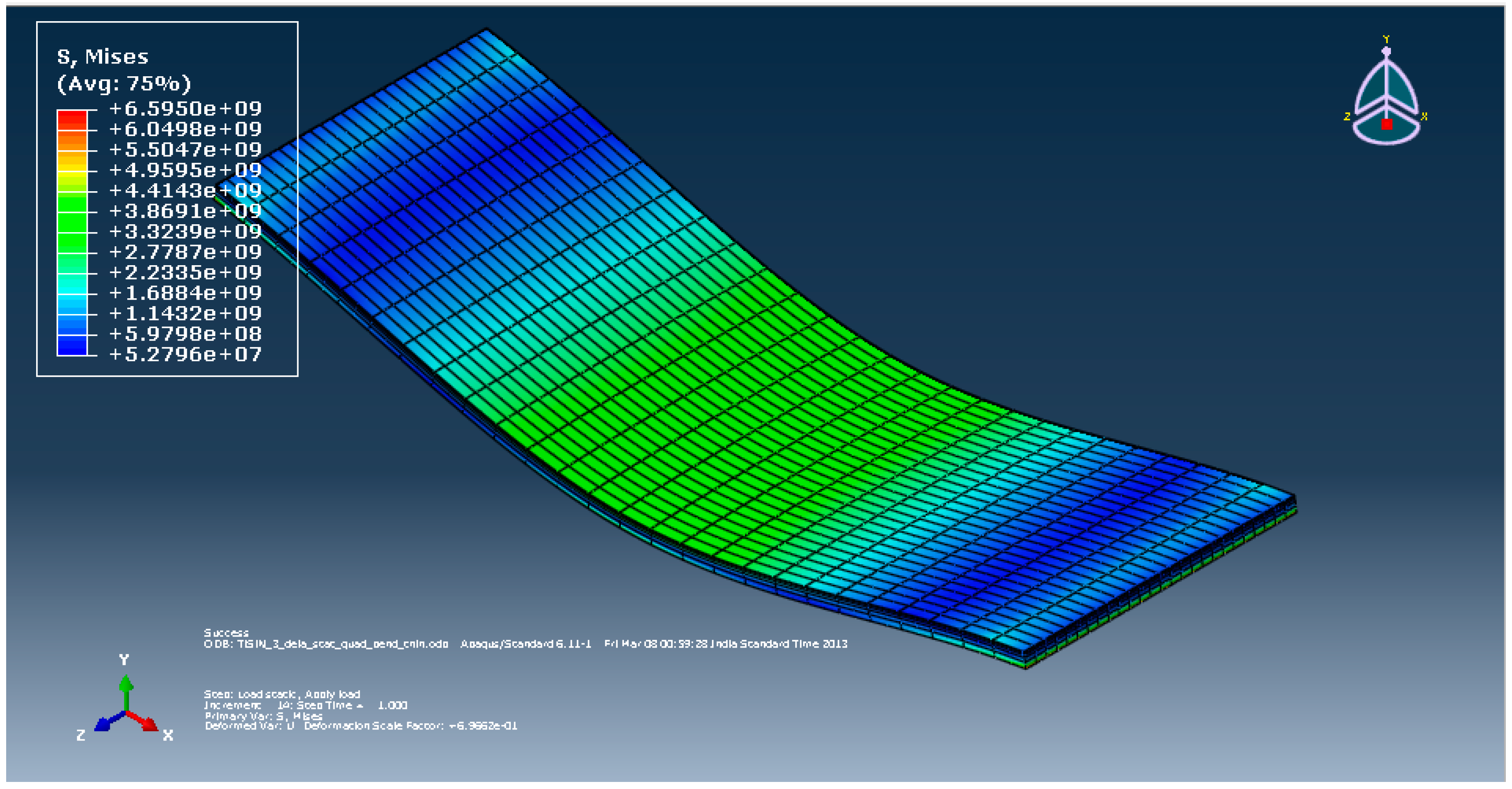
Figure 7 shows the maximum von Mises stress acting on the substrate at the junction of the coating material and substrate, situated below the loading region with different coating materials of different thicknesses.
It can be observed from
Figure 7 that the stress developed on the substrate material decreases with the increase in the coating thickness due to the increase in the section modulus of the coating–substrate assembly. Additionally, for a given thickness of the coating material, the stress developed on the substrate is maximum in the case of the DLC coating and minimum in the case of the TiSiN coating. This shows that the TiSiN coating material bears most of the stress developed due to the application of the load preventing the substrate from experiencing high stress, unlike the other coating materials.
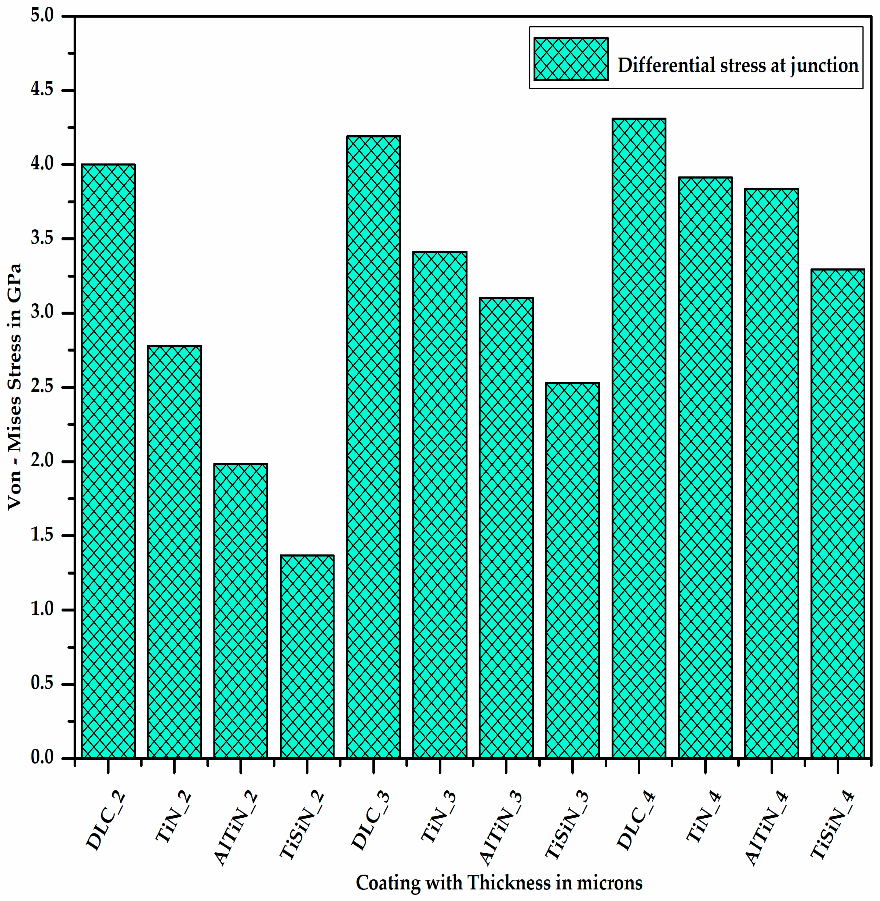
Figure 8 shows the differential stress at the junction of the coating and substrate, which is nothing but the difference of the stresses experienced by the coating material and substrate. It is clear from
Figure 8 that for a given thickness of the coating material, the differential stress between the coating material and substrate at the junction is maximum for DLC and minimum for TiSiN. As the thickness of the coating material increases, the differential stress at the junction of the coating material and substrate increases.
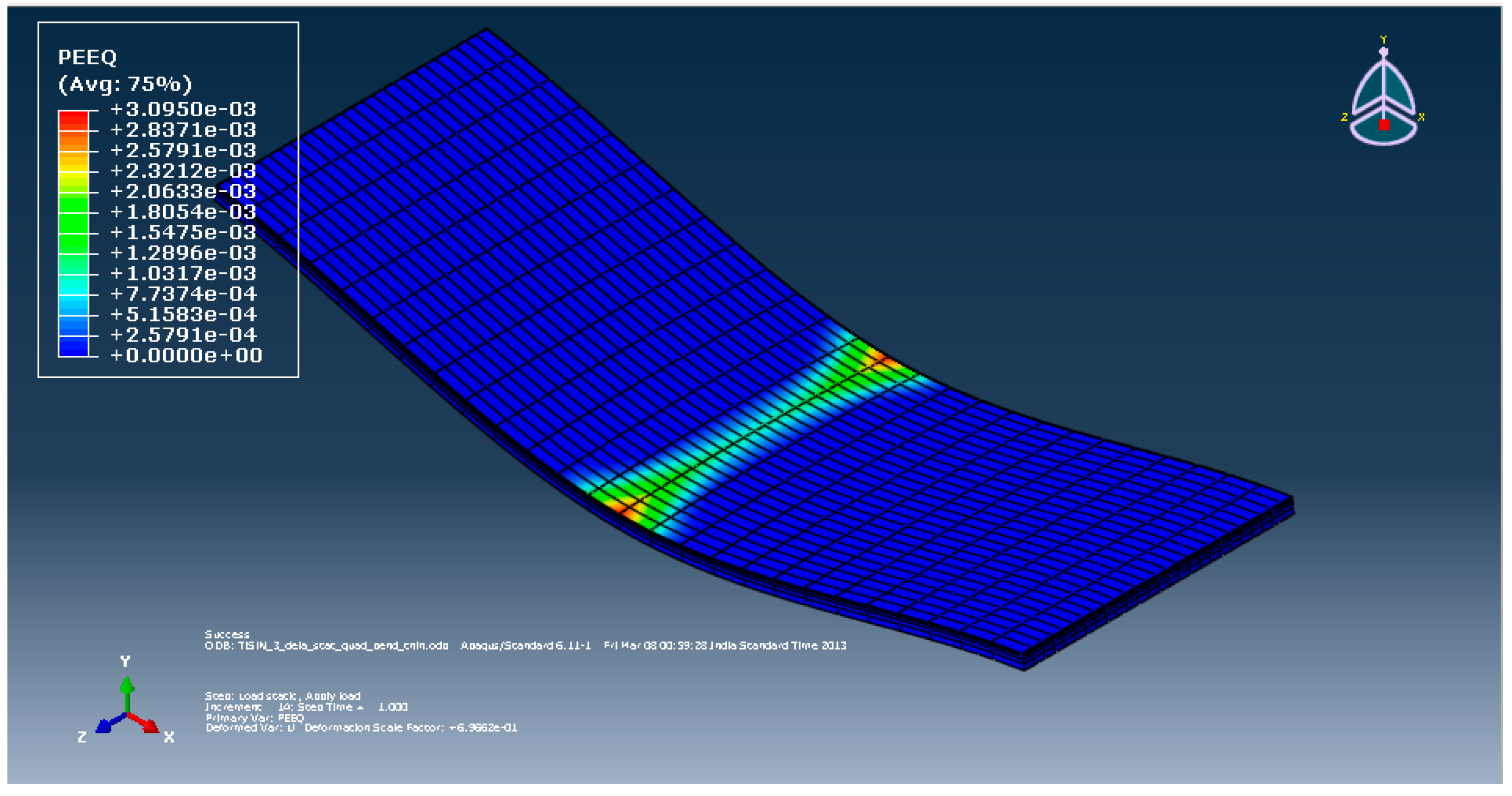
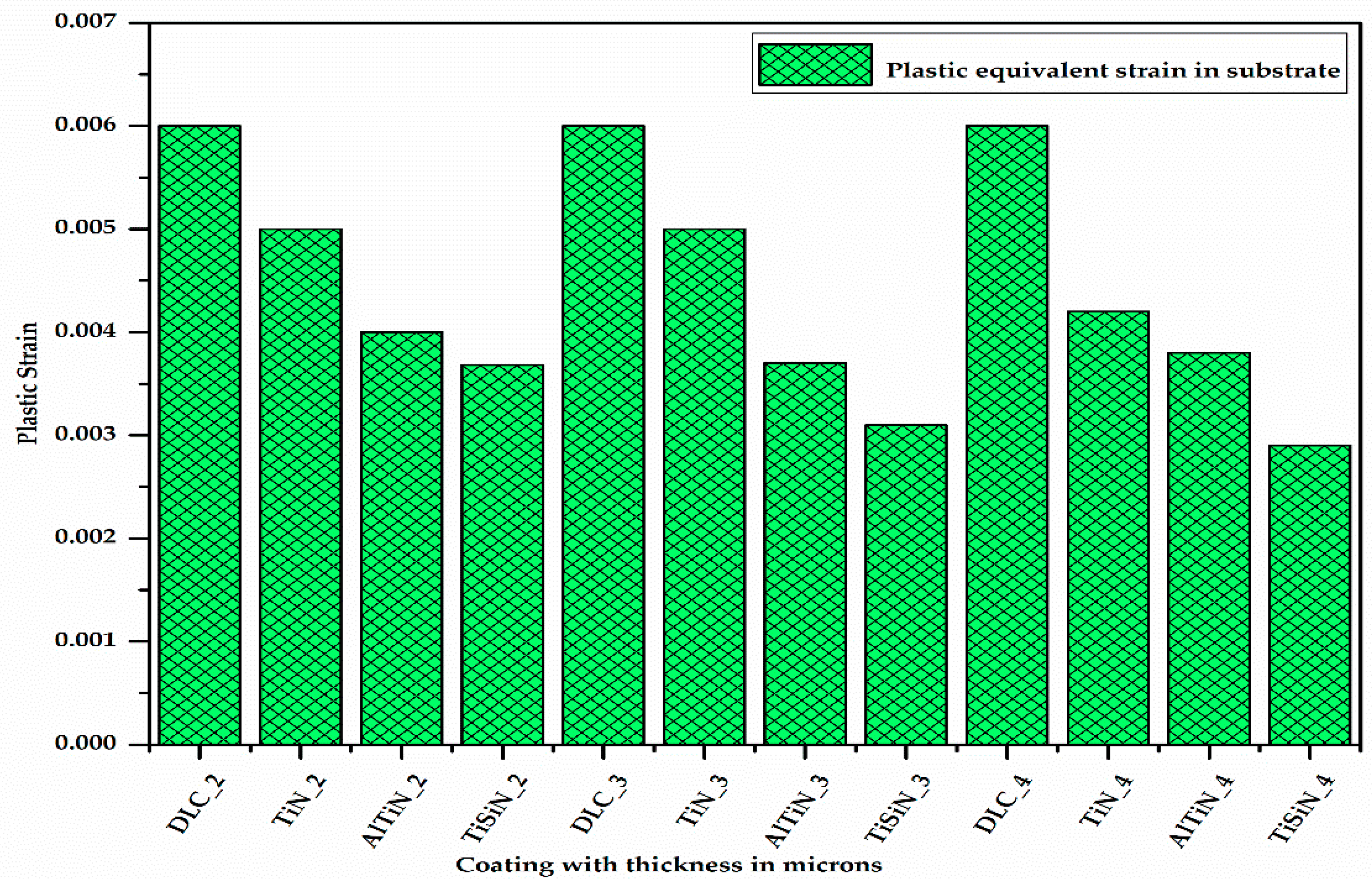
The differential stress at the junction of the substrate and coating material causes some plastic strain at the substrate surface due to the difference in the hardness of the coating material and substrate material.
Figure 9 shows the plastic equivalent strain developed on the substrate with different coating materials of different thicknesses. It can be seen from
Figure 9 that for a given coating material, as the thickness of the coating increases, the plastic equivalent strain in the substrate decreases as the stress developed in the substrate decreases. Additionally, for a given thickness of the coating, the plastic equivalent strain in the substrate is maximum for the DLC coating and minimum for the TiSiN coating.
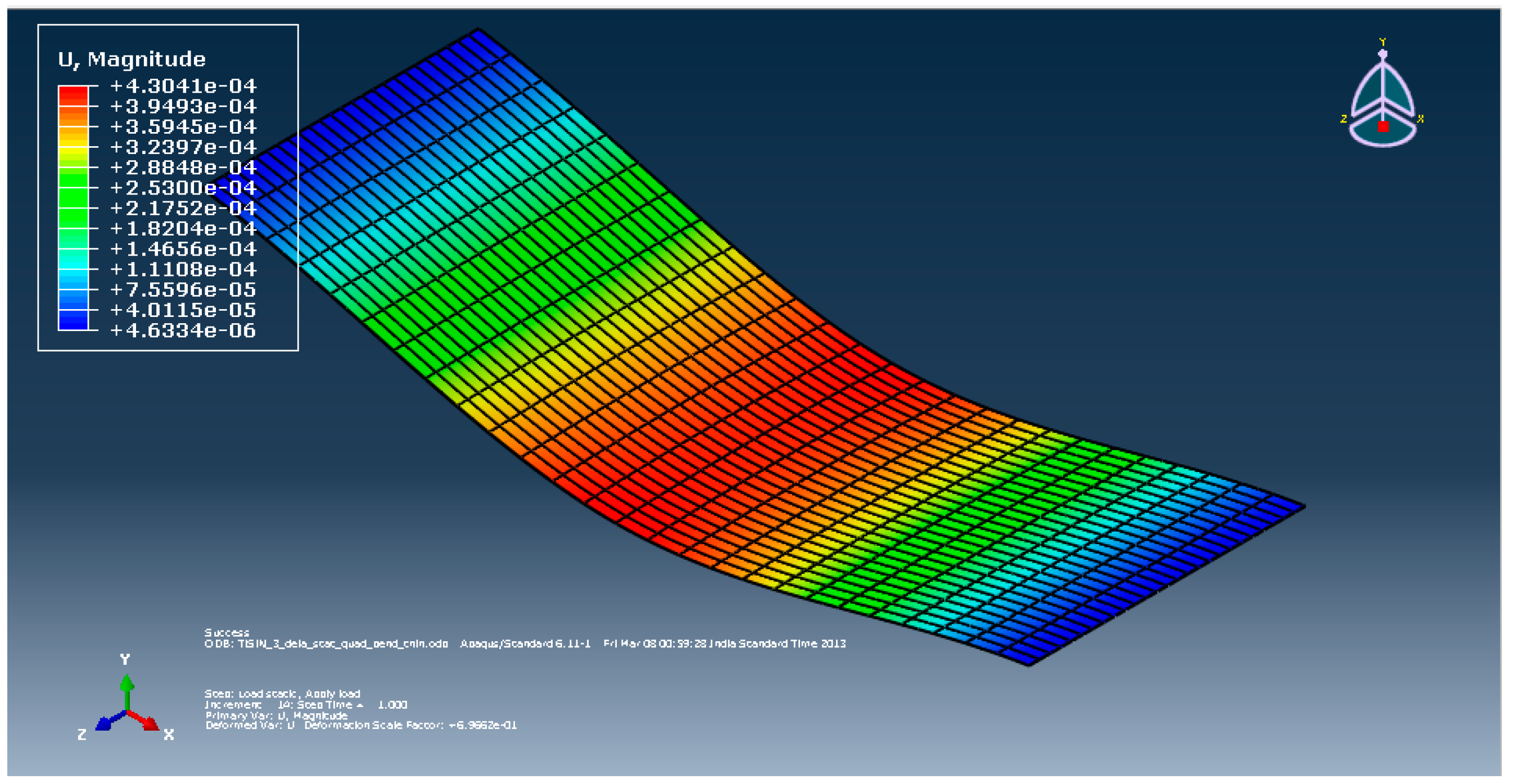
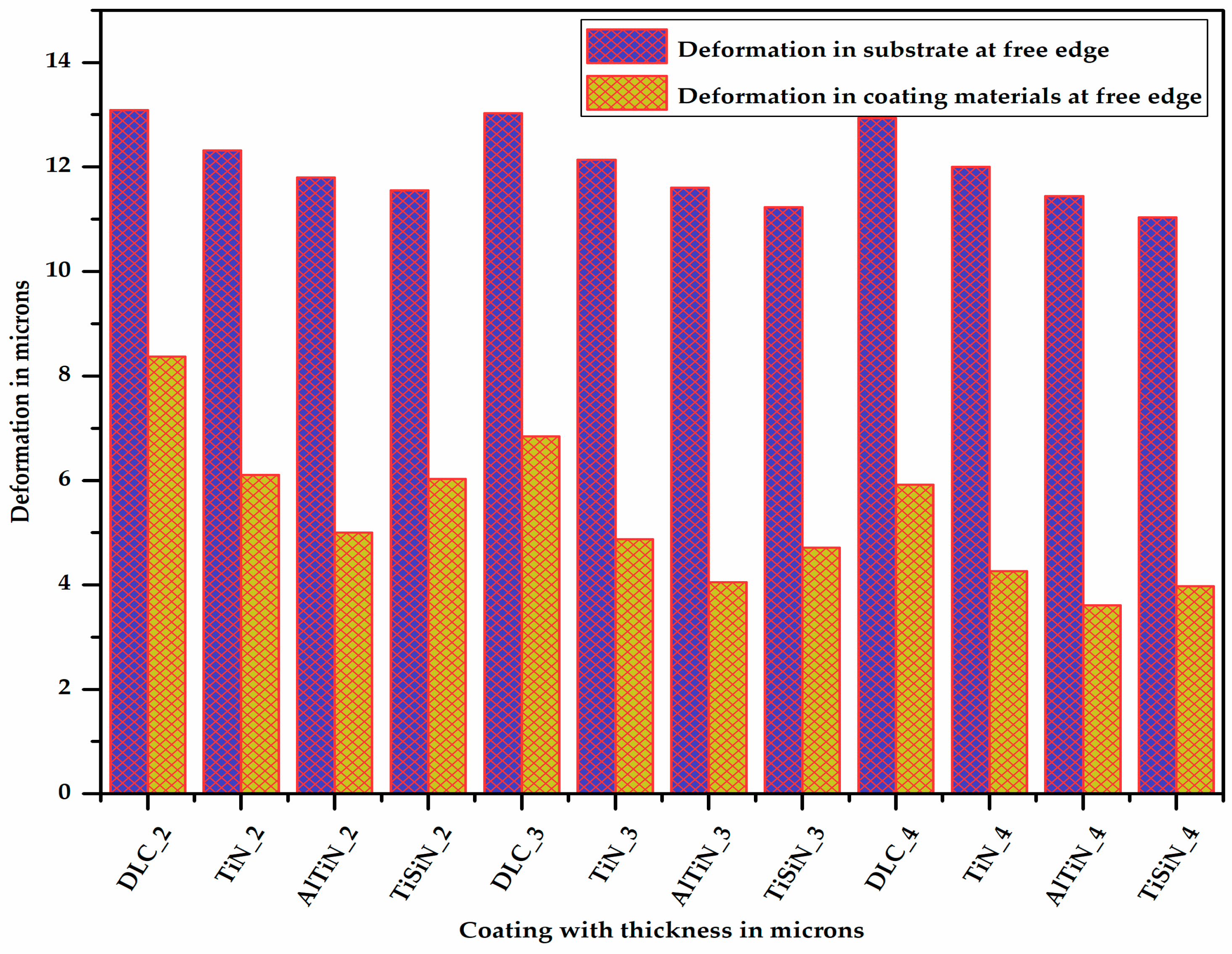
Figure 10 shows the deformation in the substrate at one of the corners at the free edge having coatings of different materials with varying thicknesses. It is very clear from
Figure 10 that as the thickness of the coating increases, the deformation in the substrate decreases. It can be also seen (Figure 13) that for a given thickness of coating, the deformation in the substrate is maximum for the DLC coating and minimum for the TiSiN coating.
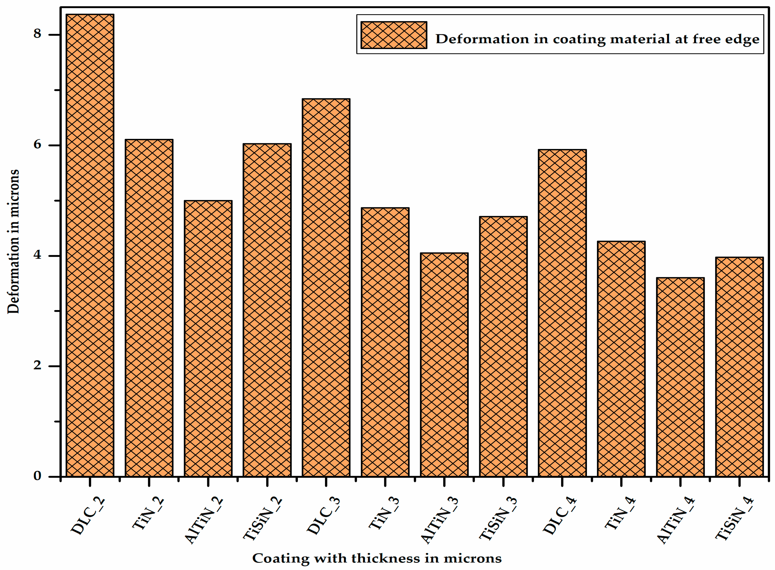
Figure 11 shows the deformation in the different coating materials of varying thicknesses at the junction of the coating material and the substrate at one of the corners of the free edge. It can be observed from Figure 13 that for a given thickness of coating, the deformation is maximum for the DLC coating and minimum for the AlTiN coating. This is because the deformation is inversely proportional to the elastic modulus. As the thickness of coating material increases, its deformation decreases due to the increase in its section modulus.
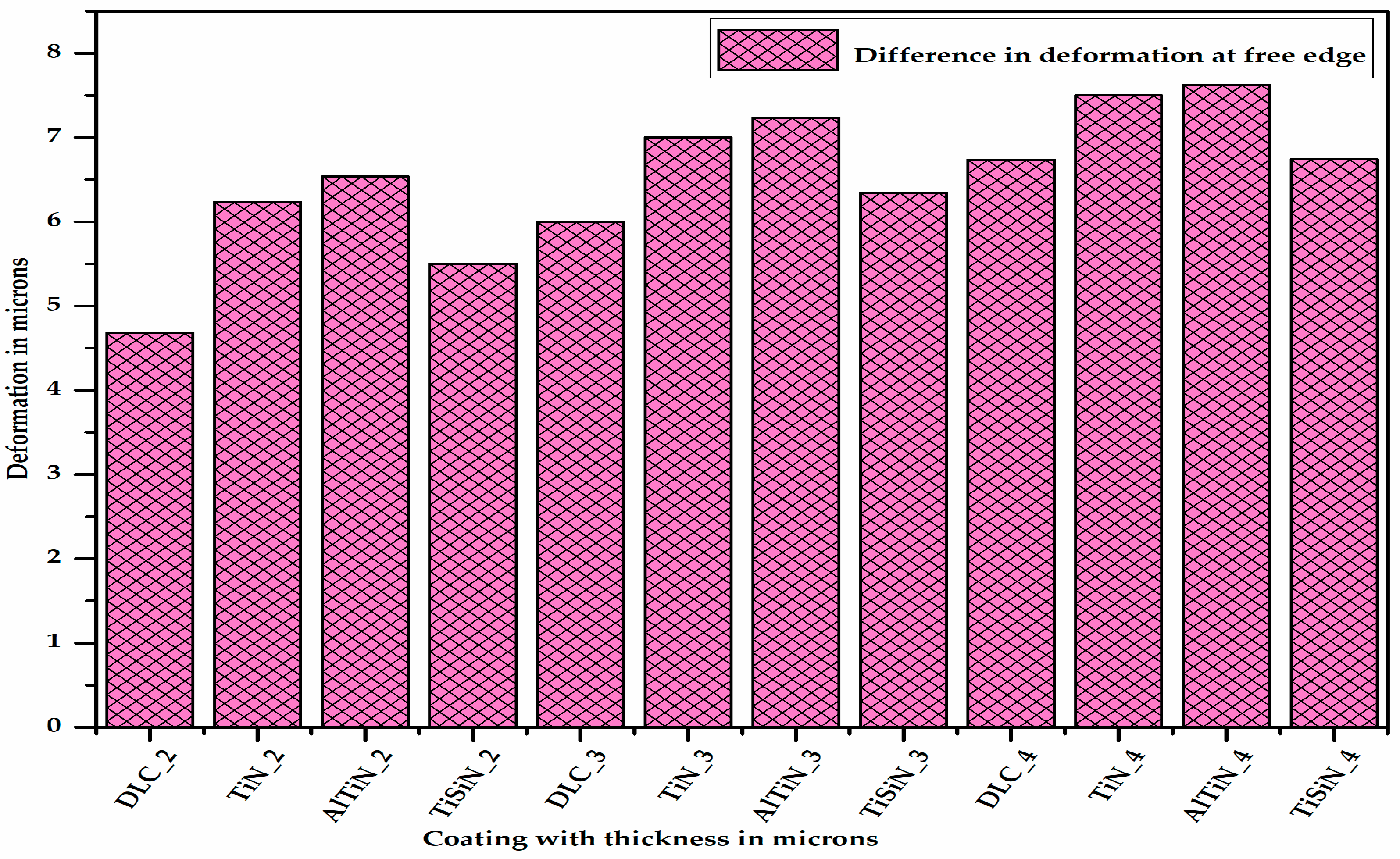
Figure 12 shows the difference in the deformation between the different coating materials of varying thicknesses and the substrate located at one of the corners at the free edge, thereby showing the extent of the delamination. It can be said from
Figure 12 that for a given thickness of coating, the difference in the deformation between the coating material and substrate is the maximum for the AlTiN coating and minimum for the DLC coating. From
Figure 13 it can be concluded that as the thickness of coating material increases, the difference in the deformation between the coating material and substrate, i.e., delamination, increases.
Because of the non-availability of FEA results in the literature, the results of the present study were not compared. However, it is clear from the result that aluminium titanium nitride coating material performs better than titanium nitride, which was reported earlier in the literature.


 ,
, 


