
Modeling and Analysis of Radial Electromagnetic Force and Vibration Characteristics Based on Deflection Dual-Stator Switched Reluctance Generator

Abstract
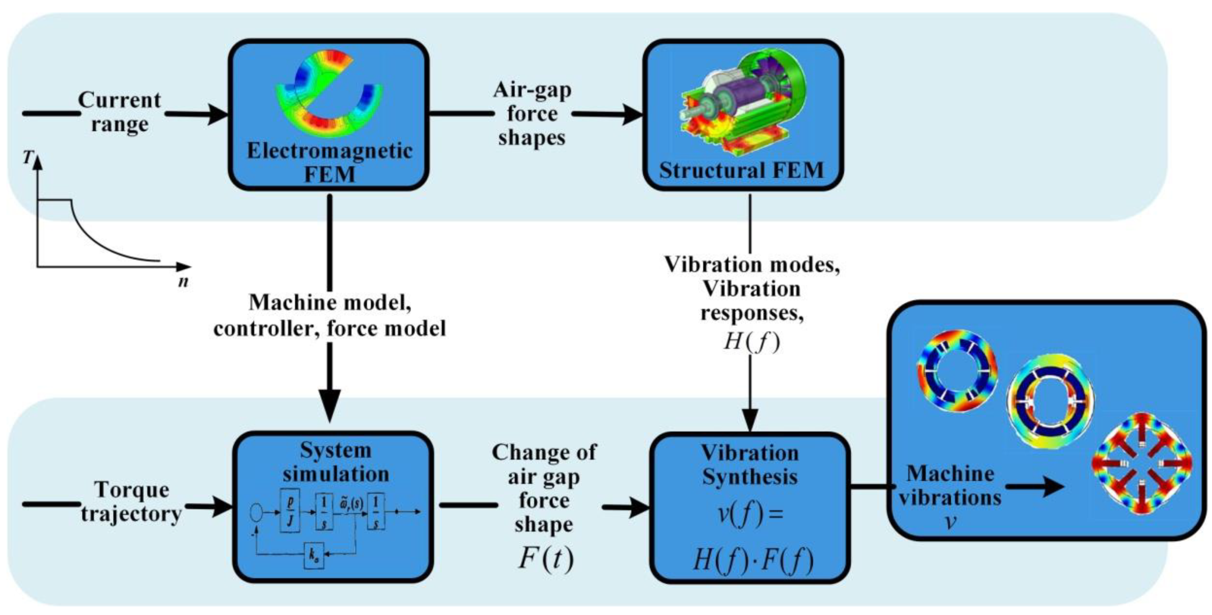
:1. Introduction
2. Design and Principle of DDSRG

| Parameter | Value |
|---|---|
| Rated speed | 200 r/min |
| Rated power | 2.5 kW |
| Rated torque | 70 N*m |
| Rated voltage | 380 V |
| External diameter of external stator | 300 mm |
| Inner diameter of inner stator | 13.5 mm |
| Rotor outer diameter | 108 mm |
| Rotor inner diameter | 43.3 mm |
| Air-gap interval | 2 mm |
| Rotor pole | 8 |
| Stator pole | 12 |
| Rotor deflection angle | 0~17° |
| Thickness of magnetic insulation board | 15 mm |
3. Analytical Calculation of Radial Electromagnetic Force and Magnetic Field
4. DDSRG Electromagnetic and Vibration Characterization
4.1. Electromagnetic Characteristic Calculation and Analysis
4.2. Modal and Vibration Analysis of DDSRG
5. Experimental Verification
6. Conclusions
Author Contributions
Funding
Institutional Review Board Statement
Informed Consent Statement
Data Availability Statement
Conflicts of Interest
References
- Kiyota, K.; Nakano, S.; Chiba, A. A fast calculation method of optimal ratio of outer diameter and axial length for torque improvement in switched reluctance motor. IEEE Trans. Ind. Appl. 2018, 54, 5802–5811. [Google Scholar] [CrossRef]
- Anvari, B.; Toliyat, H.A.; Fahimi, B. Simultaneous optimization of geometry and firing angles for in-wheel switched reluctance motor drive. IEEE Trans. Transp. Electrif. 2017, 4, 322–329. [Google Scholar] [CrossRef]
- Chen, H.C.; Wang, W.A.; Huang, B.W. Integrated driving/charging/discharging battery-powered four-phase switched reluctance motor drive with two current sensors. IEEE Trans. Power Electron. 2018, 34, 5019–5022. [Google Scholar] [CrossRef]
- Cai, J.; Zhao, X. An on-board charger integrated power converter for EV switched reluctance motor drives. IEEE Trans. Ind. Electron. 2020, 68, 3683–3692. [Google Scholar] [CrossRef]
- Diao, K.; Sun, X.; Lei, G.; Guo, Y.; Zhu, J. Multimode optimization of switched reluctance machines in hybrid electric vehicles. IEEE Trans. Energy Convers. 2020, 36, 2217–2226. [Google Scholar] [CrossRef]
- Fang, G.; Scalcon, F.P.; Xiao, D.; Vieira, R.P.; Gründling, H.A.; Emadi, A. Advanced control of switched reluctance motors (SRMs): A review on current regulation, torque control and vibration suppression. IEEE Open J. Ind. Electron. Soc. 2021, 2, 280–301. [Google Scholar] [CrossRef]
- Guo, X.; Zhong, R.; Zhang, M.; Ding, D.; Sun, W. Resonance reduction by optimal switch angle selection in switched reluctance motor. IEEE Trans. Ind. Electron. 2019, 67, 1867–1877. [Google Scholar] [CrossRef]
- Gundogmus, O.; Das, S.; Yasa, Y.; Elamin, M.; Sozer, Y.; Kutz, J.; Wright, R.L. Acoustic Noise Mitigation in High Pole Count Switched Reluctance Machines Utilizing Skewing Method on Stator and Rotor Poles. IEEE Trans. Ind. Electron. 2021, 69, 5581–5593. [Google Scholar] [CrossRef]
- YAŞA, Y.; Sözer, Y.; Garip, M. High-speed switched reluctance machine: Natural frequency calculation and acoustic noise prediction. Turk. J. Electr. Electron. Elec. Eng. Comp. Sci. 2018, 26, 999–1010. [Google Scholar] [CrossRef]
- Wang, H.; Bao, J.; Xue, B.; Liu, J. Control of suspending force in novel permanent-magnet-biased bearingless switched reluctance motor. IEEE Trans. Ind. Electron. 2015, 62, 4298–4306. [Google Scholar] [CrossRef]
- Liang, J.; Howey, B.; Bilgin, B.; Emadi, A. Source of acoustic noise in a 12/16 external-Rotor switched reluctance motor: Stator tangential vibration and rotor radial vibration. IEEE Open J. Ind. Appl. 2020, 1, 63–73. [Google Scholar] [CrossRef]
- Makino, H.; Kosaka, T.; Matsui, N. Digital PWM-control-based active vibration cancellation for switched reluctance motors. IEEE Trans. Ind. Appl. 2015, 51, 4521–4530. [Google Scholar] [CrossRef]
- Shin, S.; Kawagoe, N.; Kosaka, T.; Matsui, N. Study on commutation control method for reducing noise and vibration in SRM. IEEE Trans. Ind. Appl. 2018, 54, 4415–4424. [Google Scholar] [CrossRef]
- Tanabe, A.; Akatsu, K. Vibration reduction method in SRM with a smoothing voltage commutation by PWM. In Proceedings of the 9th International Conference on Power Electronics and ECCE Asia (ICPE-ECCE Asia), Seoul, Korea, 1–5 June 2015; pp. 600–604. [Google Scholar]
- Pupadubsin, R.; Mecrow, B.C.; Widmer, J.D.; Steven, A. Smooth voltage pwm for vibration and acoustic noise reduction in switched reluctance machines. IEEE Trans. Energy Convers. 2020, 36, 1578–1588. [Google Scholar] [CrossRef]
- Zhang, M.; Bahri, I.; Mininger, X.; Vlad, C.; Xie, H.; Berthelot, E. A new control method for vibration and noise suppression in switched reluctance machines. Energies 2019, 12, 1554. [Google Scholar] [CrossRef]
- Zhang, M.; Bahri, I.; Mininger, X.; Vlad, C.; Xie, H.; Berthelot, E.; Hu, W. Vibration reduction controller for a switched reluctance machine based on hw/sw partitioning. IEEE Trans. Industr. Inform. 2020, 17, 3879–3889. [Google Scholar] [CrossRef]
- Zhang, M.; Bahri, I.; Mininger, X.; Vlad, C.; Berthelot, E. Vibration reduction control of switched reluctance machine. IEEE Trans. Energy Convers. 2019, 34, 1380–1390. [Google Scholar] [CrossRef]
- Salameh, M.; Singh, S.; Li, S.; Krishnamurthy, M. Surrogate vibration modeling approach for design optimization of electric machines. IEEE Trans. Transp. Electrif. 2020, 6, 1126–1133. [Google Scholar] [CrossRef]
- Xu, Z.; Yu, Q.; Zhang, F. Design and Analysis of Asymmetric Rotor Pole Type Bearingless Switched Reluctance Motor. CES TEMS 2022, 6, 3–10. [Google Scholar] [CrossRef]
- Fiedler, J.O.; Kasper, K.A.; De Doncker, R.W. Calculation of the acoustic noise spectrum of SRM using modal superposition. IEEE Trans. Ind. Electron. 2010, 57, 2939–2945. [Google Scholar] [CrossRef]
- Mathis, A.T.; Dane Quinn, D.; El-Amin, M.; Sozer, Y. Mechanical analysis of vibrations in a switched reluctance motor using experimental, numerical, and analytical methodologies. J. Vib. Acoust. 2019, 141, 031007.1–031007.8. [Google Scholar] [CrossRef]
- Liang, J.; Callegaro, A.D.; Bilgin, B.; Emadi, A. A novel three-dimensional analytical approach for acoustic noise modeling in switched reluctance machines. IEEE Trans. Energy Convers. 2021, 36, 2099–2109. [Google Scholar] [CrossRef]
- Gong, C.; Li, S.; Habetler, T.; Zhou, P. Acoustic modeling and prediction of ultrahigh-speed switched reluctance machines based on multiphysics finite element analysis. IEEE Trans. Ind. Appl. 2020, 57, 198–207. [Google Scholar] [CrossRef]
- Liang, X.; Li, G.; Ojeda, J.; Gabsi, M.; Ren, Z. Comparative study of classical and mutually coupled switched reluctance motors using multiphysics finite-element modeling. IEEE Trans. Ind. Electron. 2013, 61, 5066–5074. [Google Scholar] [CrossRef]
- Han, L.; Wang, D.; Yang, F.; He, W. Vibration Characteristics of the Dual Electric Propulsion System of Vessels under Electromechanical Coupling Excitation. Machines 2022, 10, 449. [Google Scholar] [CrossRef]
- Li, Z.; Yu, X.; Qian, Z.; Wang, X.; Xiao, Y.; Sun, H. Generation Characteristics Analysis of Deflection Type Double Stator Switched Reluctance Generator. IEEE Access 2020, 8, 196175–196186. [Google Scholar] [CrossRef]
- Song, T.; Liu, H.; Bu, B.; Zhang, Z. Rapid Calculation and Optimization of Vibration and Noise of Permanent-Magnet Synchronous Motors for EVs Based on Equivalent Structural Network. Machines 2022, 10, 281. [Google Scholar] [CrossRef]
- Wu, S.; Zuo, S. Characteristics analysis of electromagnetic force and noise of claw pole alternators with different pole and slot combinations and phase number. IET Electric. Power Appl. 2018, 12, 1357–1364. [Google Scholar] [CrossRef]
- Hu, S.; Zuo, S. Analytical modeling of magnetic field considering the saturation in switched reluctance motor. Appl. Comput. Electromagn. Soc. J. 2018, 33, 1467–1474. [Google Scholar]


| Parameter | Value |
|---|---|
| Modulus of elasticity | 2.06 × 10¹¹ Pa |
| Poisson’s ratio | 0.3 |
| Density | 7884 kg/m3 |
Publisher’s Note: MDPI stays neutral with regard to jurisdictional claims in published maps and institutional affiliations. |
© 2022 by the authors. Licensee MDPI, Basel, Switzerland. This article is an open access article distributed under the terms and conditions of the Creative Commons Attribution (CC BY) license (https://creativecommons.org/licenses/by/4.0/).
Share and Cite
Li, Z.; Liu, L.; Wang, P.; Liu, Y.; Wei, X.; Xu, Q.; Sun, H. Modeling and Analysis of Radial Electromagnetic Force and Vibration Characteristics Based on Deflection Dual-Stator Switched Reluctance Generator. Micromachines 2022, 13, 1494. https://doi.org/10.3390/mi13091494
Li Z, Liu L, Wang P, Liu Y, Wei X, Xu Q, Sun H. Modeling and Analysis of Radial Electromagnetic Force and Vibration Characteristics Based on Deflection Dual-Stator Switched Reluctance Generator. Micromachines. 2022; 13(9):1494. https://doi.org/10.3390/mi13091494
Chicago/Turabian StyleLi, Zheng, Libo Liu, Pengju Wang, Yu Liu, Xiaopeng Wei, Qianqian Xu, and Hexu Sun. 2022. "Modeling and Analysis of Radial Electromagnetic Force and Vibration Characteristics Based on Deflection Dual-Stator Switched Reluctance Generator" Micromachines 13, no. 9: 1494. https://doi.org/10.3390/mi13091494
APA StyleLi, Z., Liu, L., Wang, P., Liu, Y., Wei, X., Xu, Q., & Sun, H. (2022). Modeling and Analysis of Radial Electromagnetic Force and Vibration Characteristics Based on Deflection Dual-Stator Switched Reluctance Generator. Micromachines, 13(9), 1494. https://doi.org/10.3390/mi13091494