
The Influence of Aligned MHD on Engine Oil-Based Casson Nanofluid with Carbon Nanotubes (Single and Multi-Wall) Passing through a Shrinking Sheet with Thermal Radiation and Wall Mass Exchange

Abstract
:1. Introduction
2. Novelty and Applications
3. Flow Analysis
4. Heat Transfer Analysis
5. Skin Friction and Local Nusselt Number
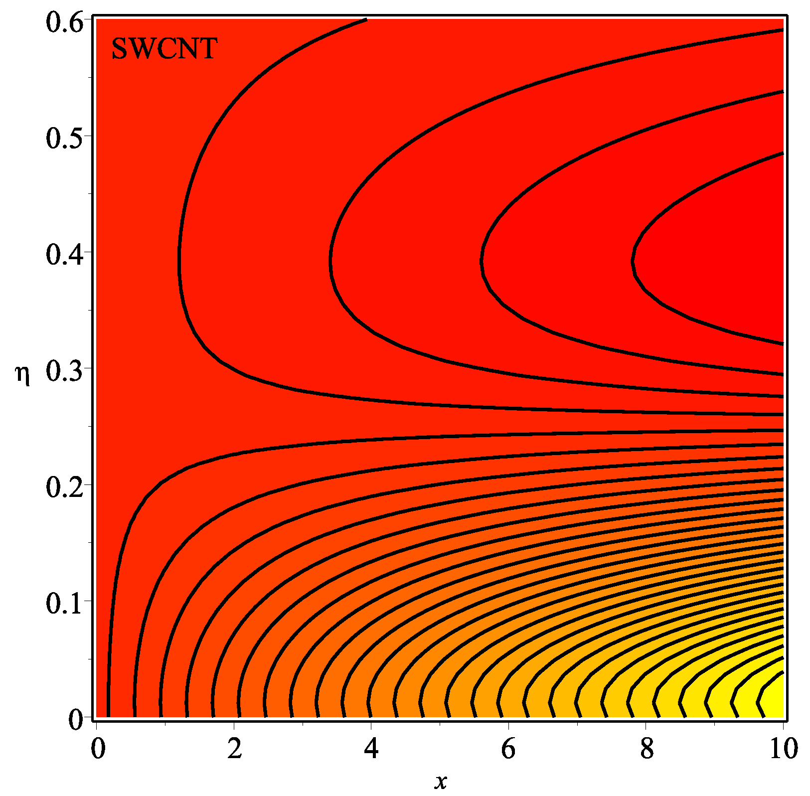
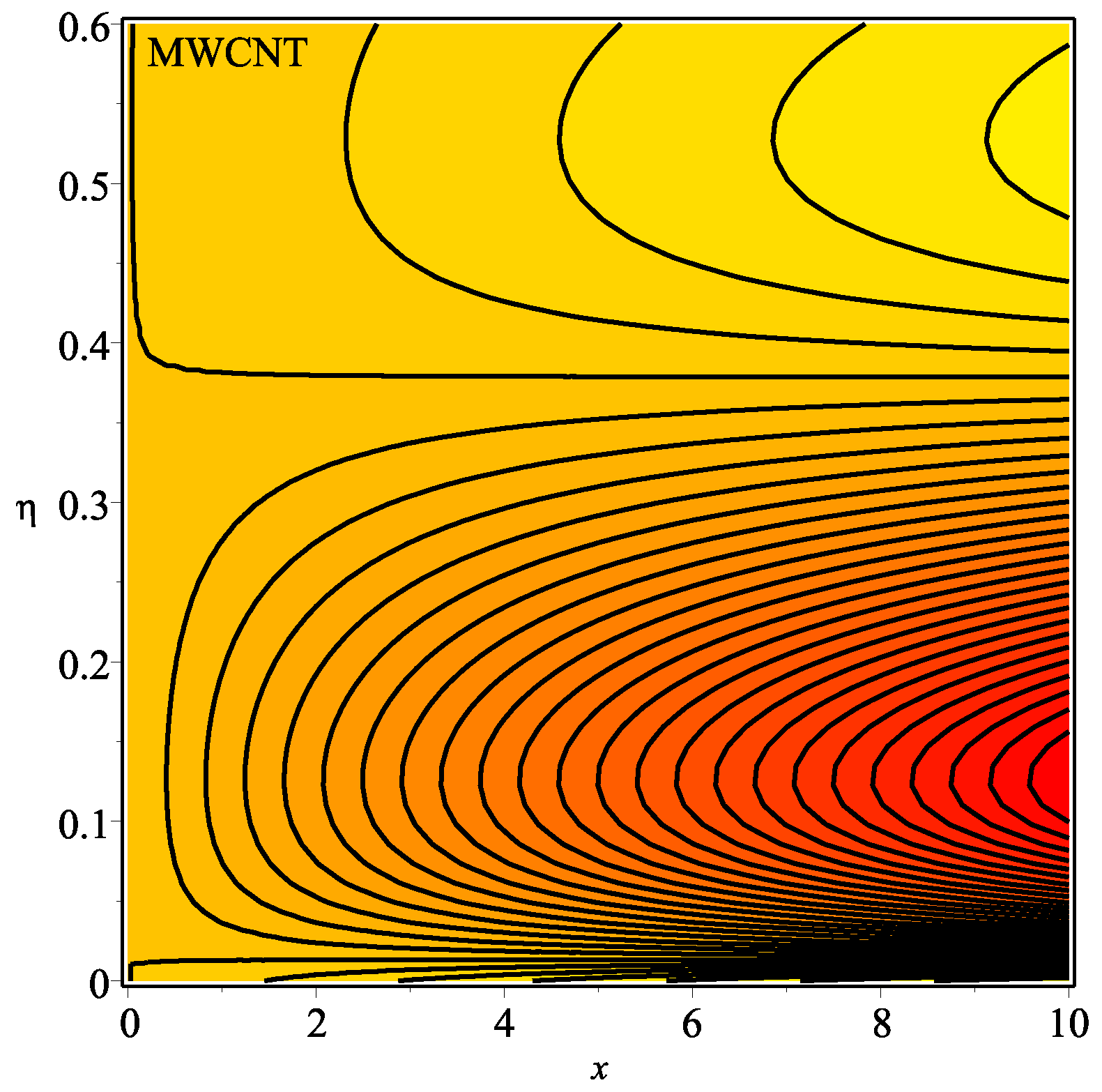
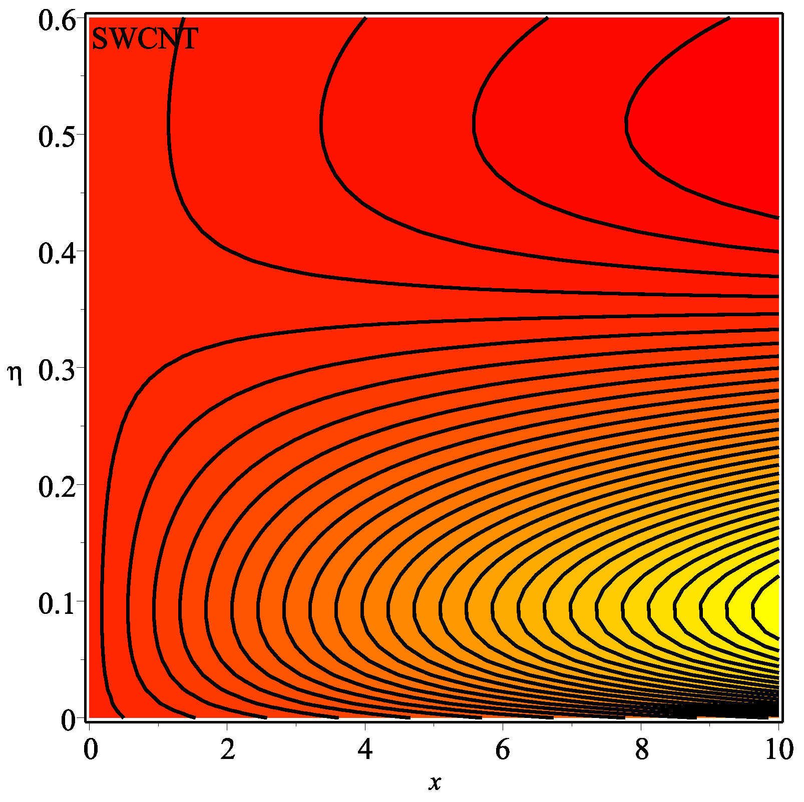
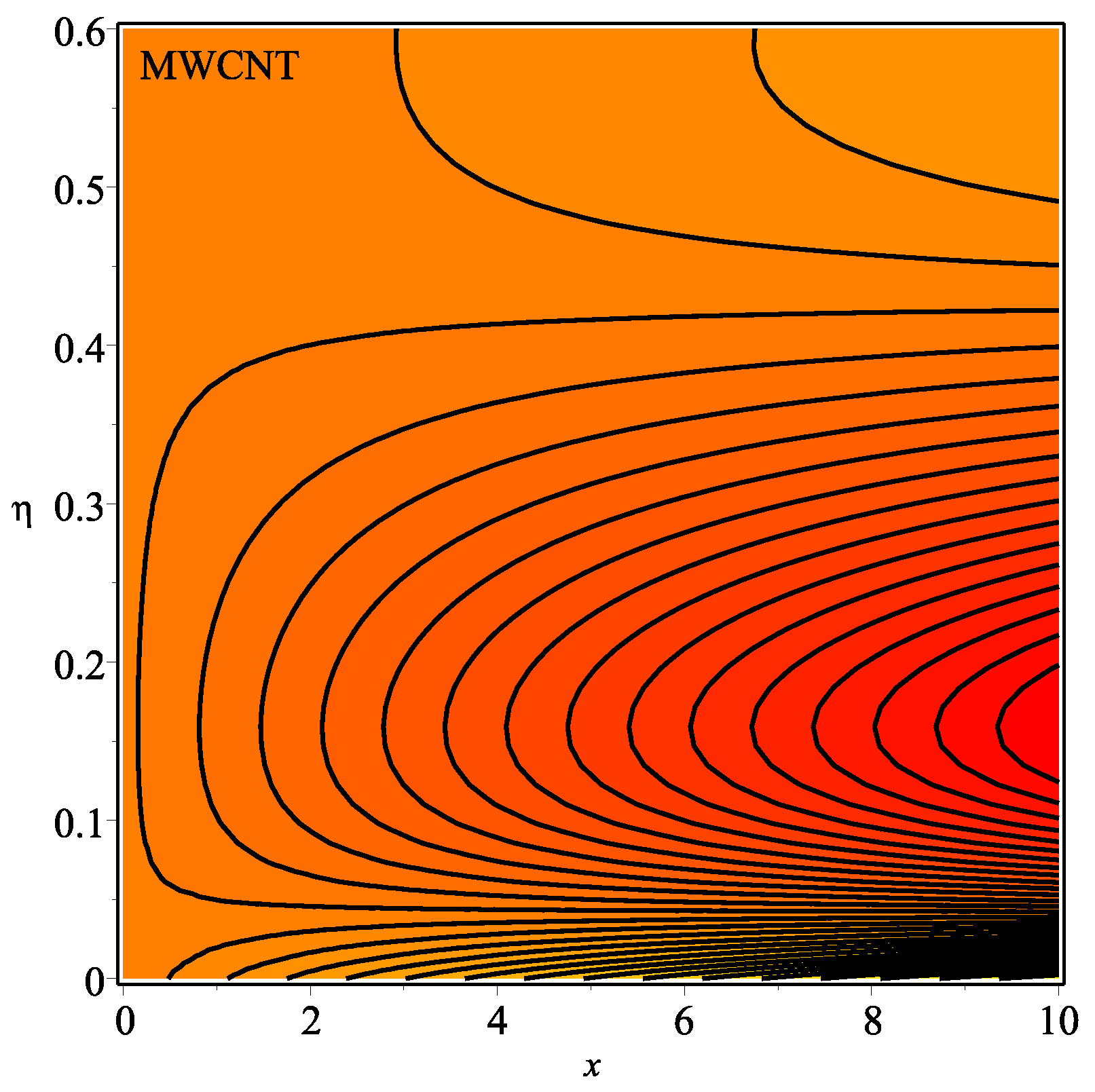
6. Results and Discussion
7. Conclusions
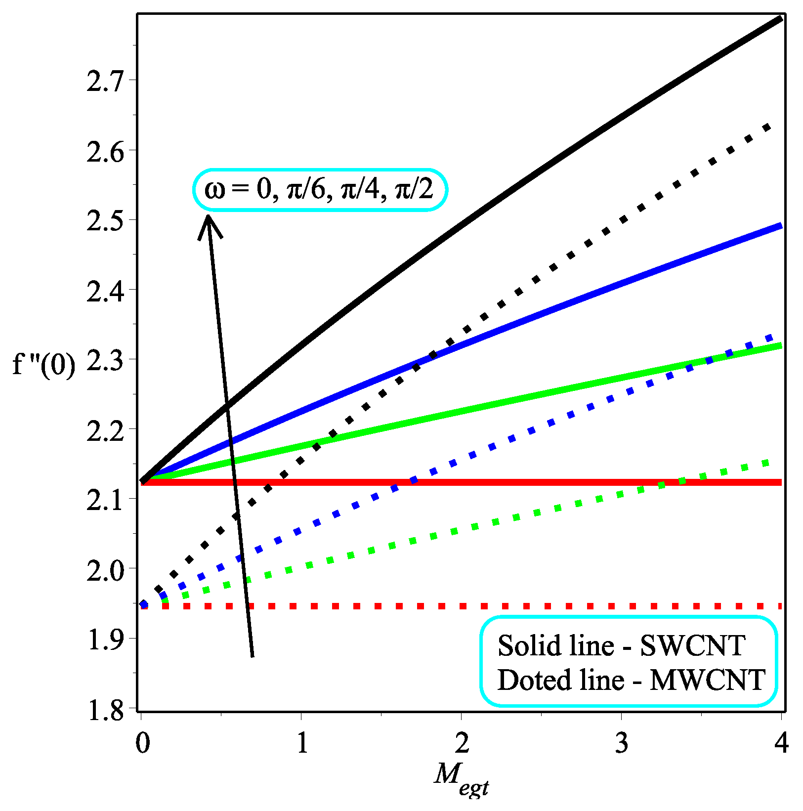
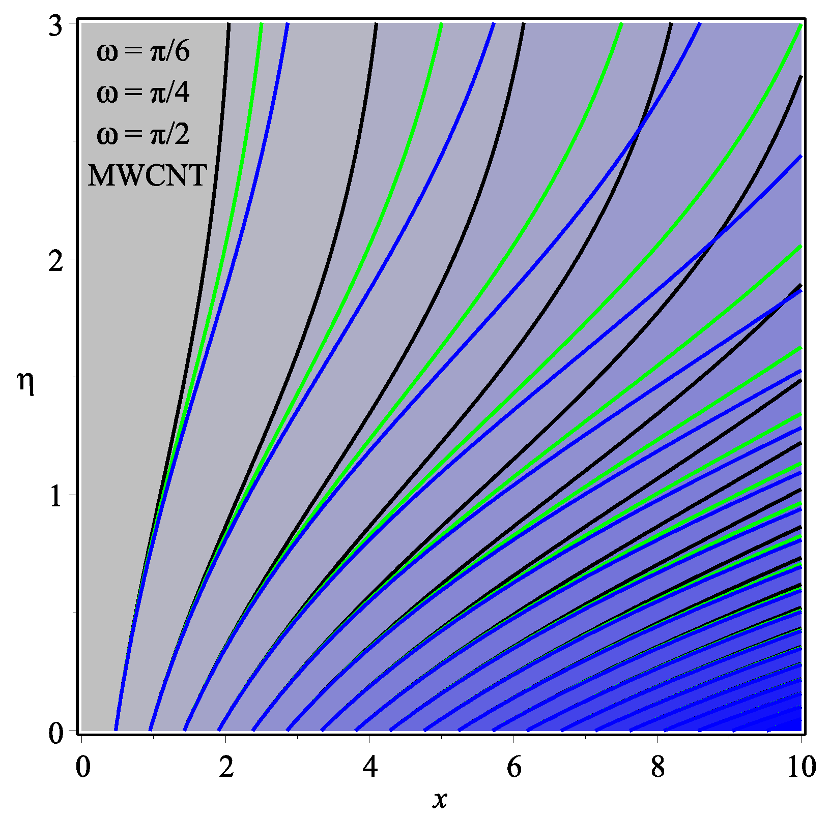
- When , the magnetic field has no effect on the velocity distribution, but it behaves transversely when across the stream portion.
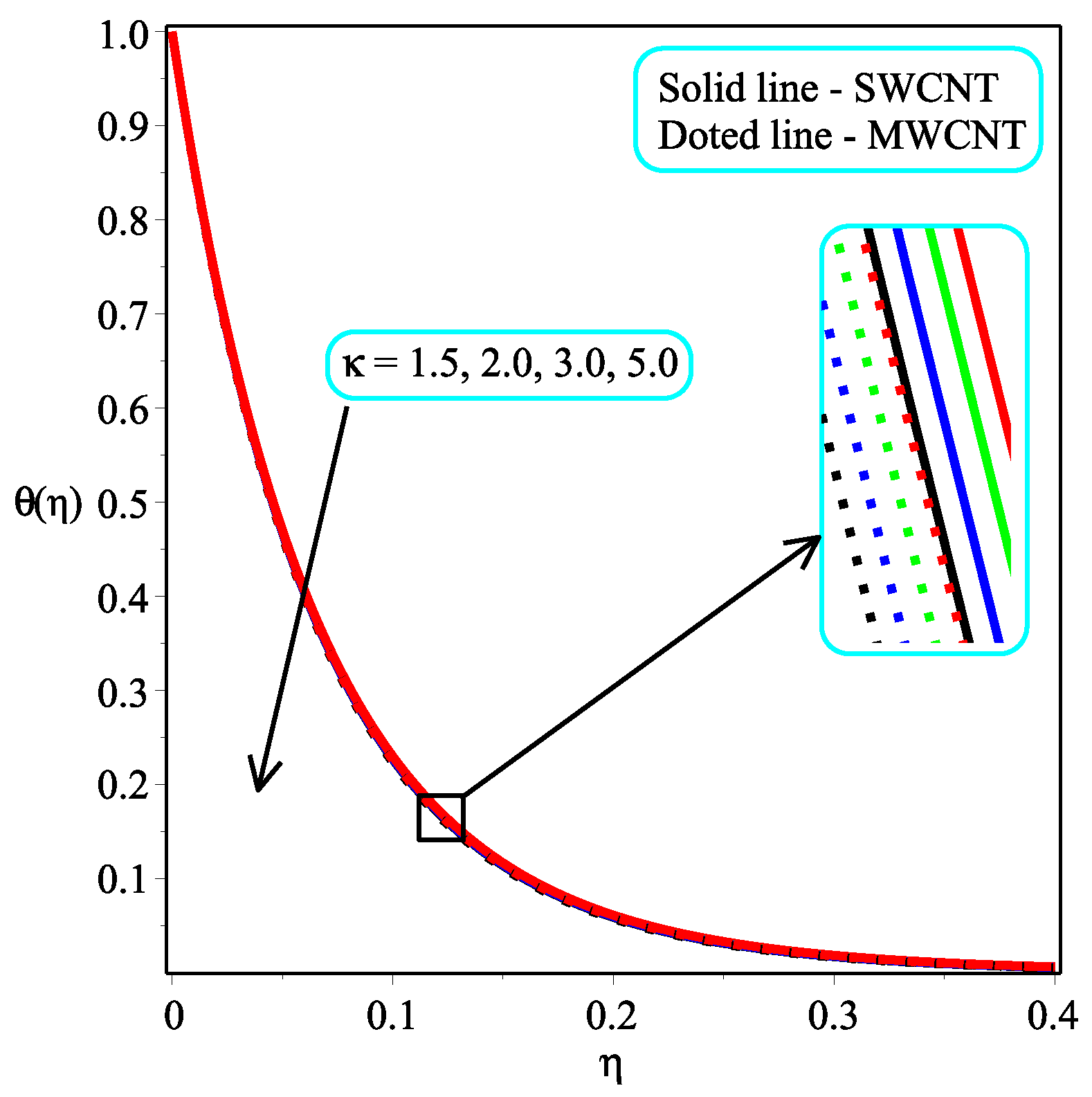
- The temperature distribution can be controlled through the power law index N.
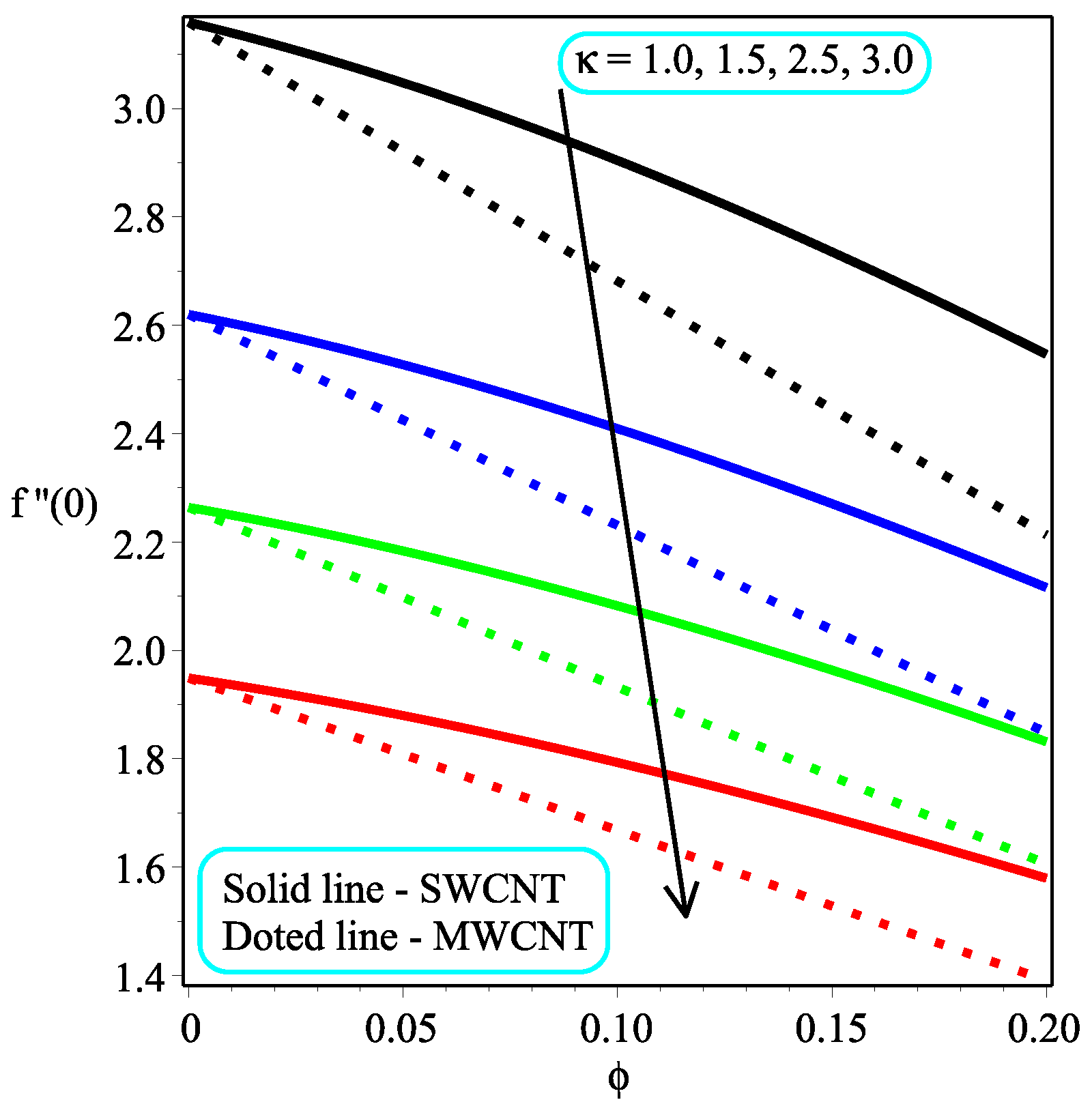
- An increase in and leads to a decline in the value of skin friction at the wall, and the skin friction at the wall rate is dropped in the multi-walled CNTs rapidly as compared to the single-walled CNTs.
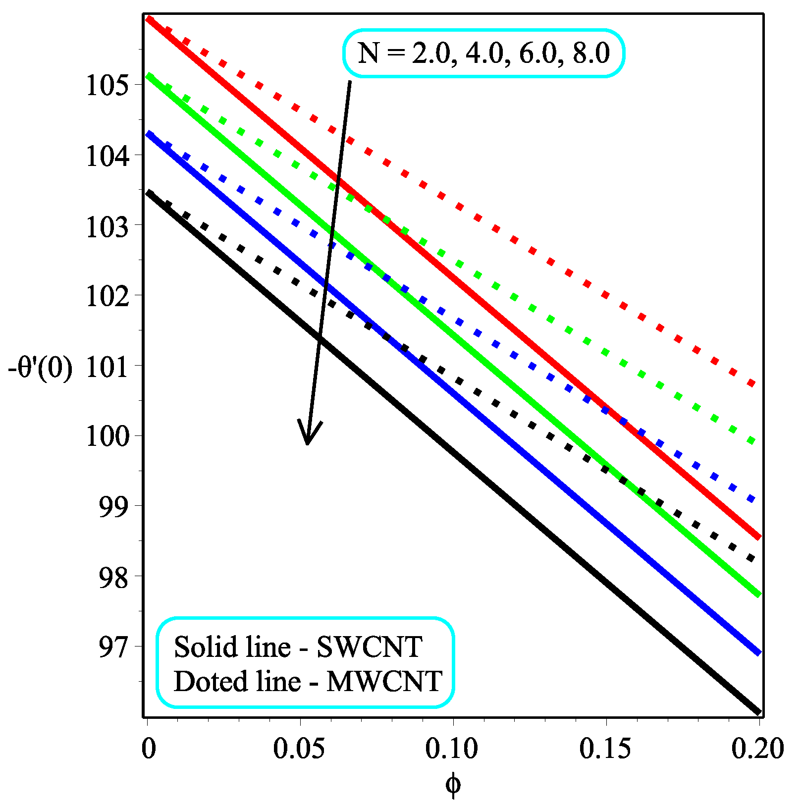
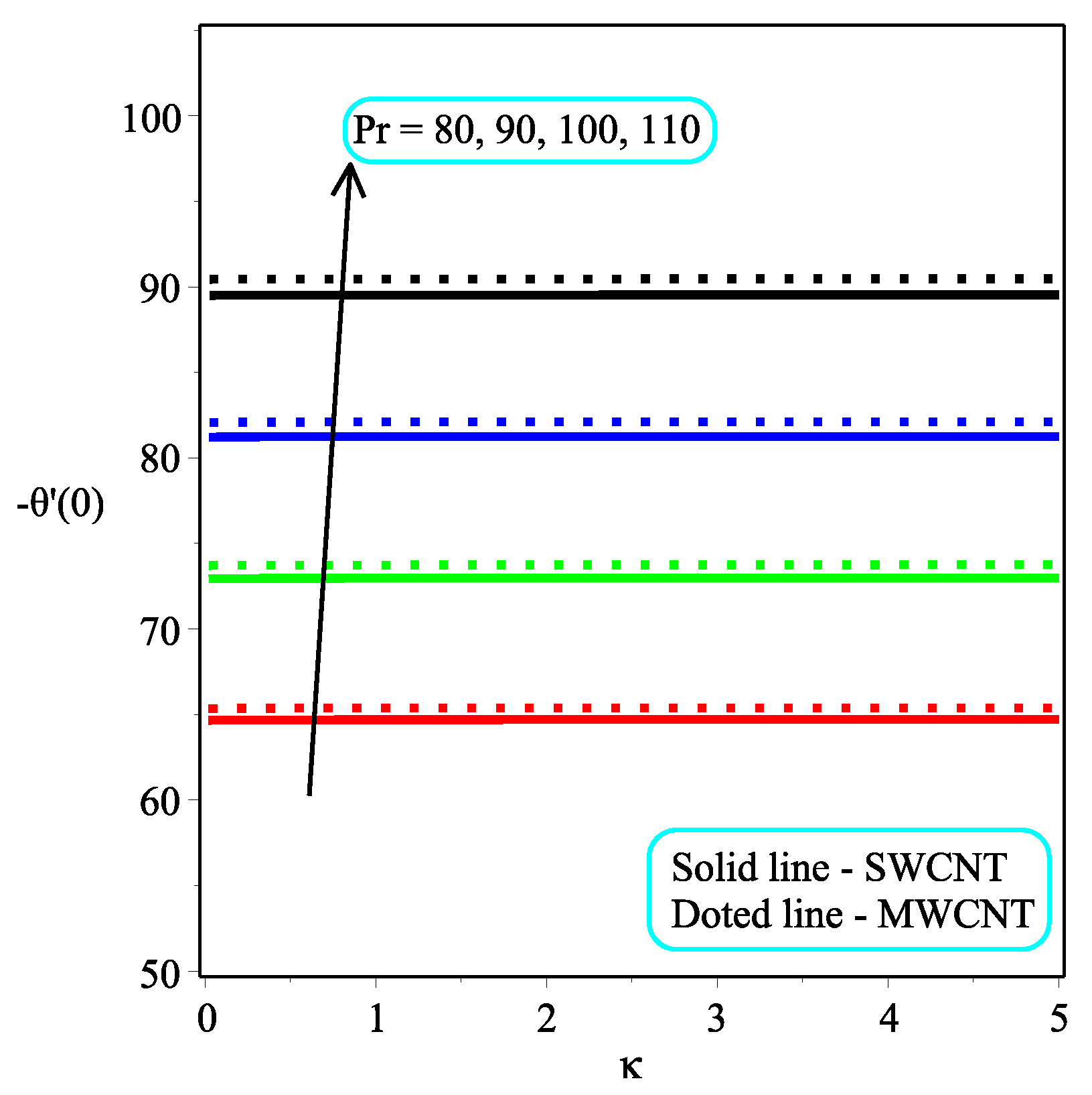
- The injection parameter decreases the heat transfer rate of the sheet. The single-walled CNTs have a less degradation rate as compared to multi-walled CNTs.
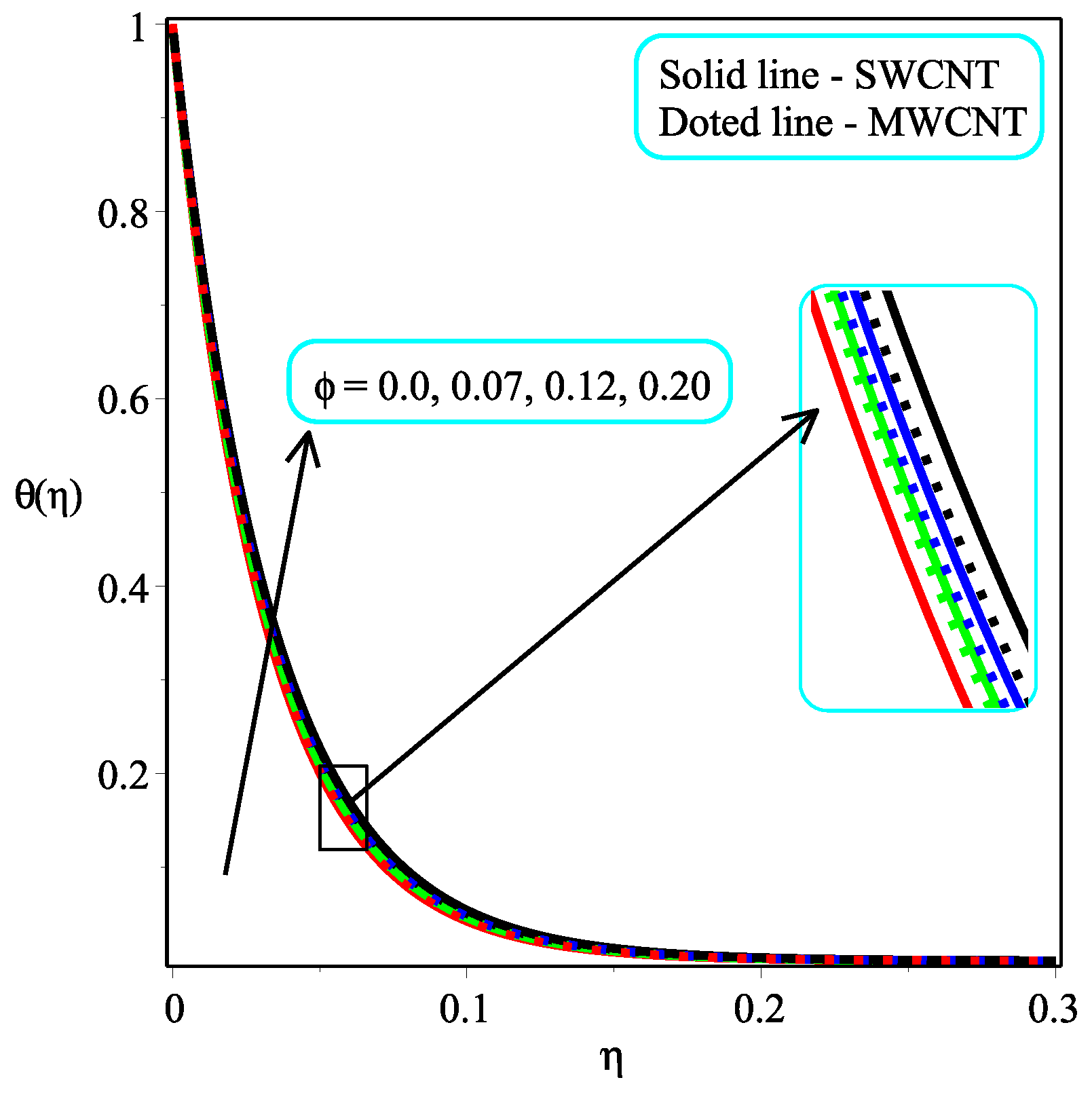
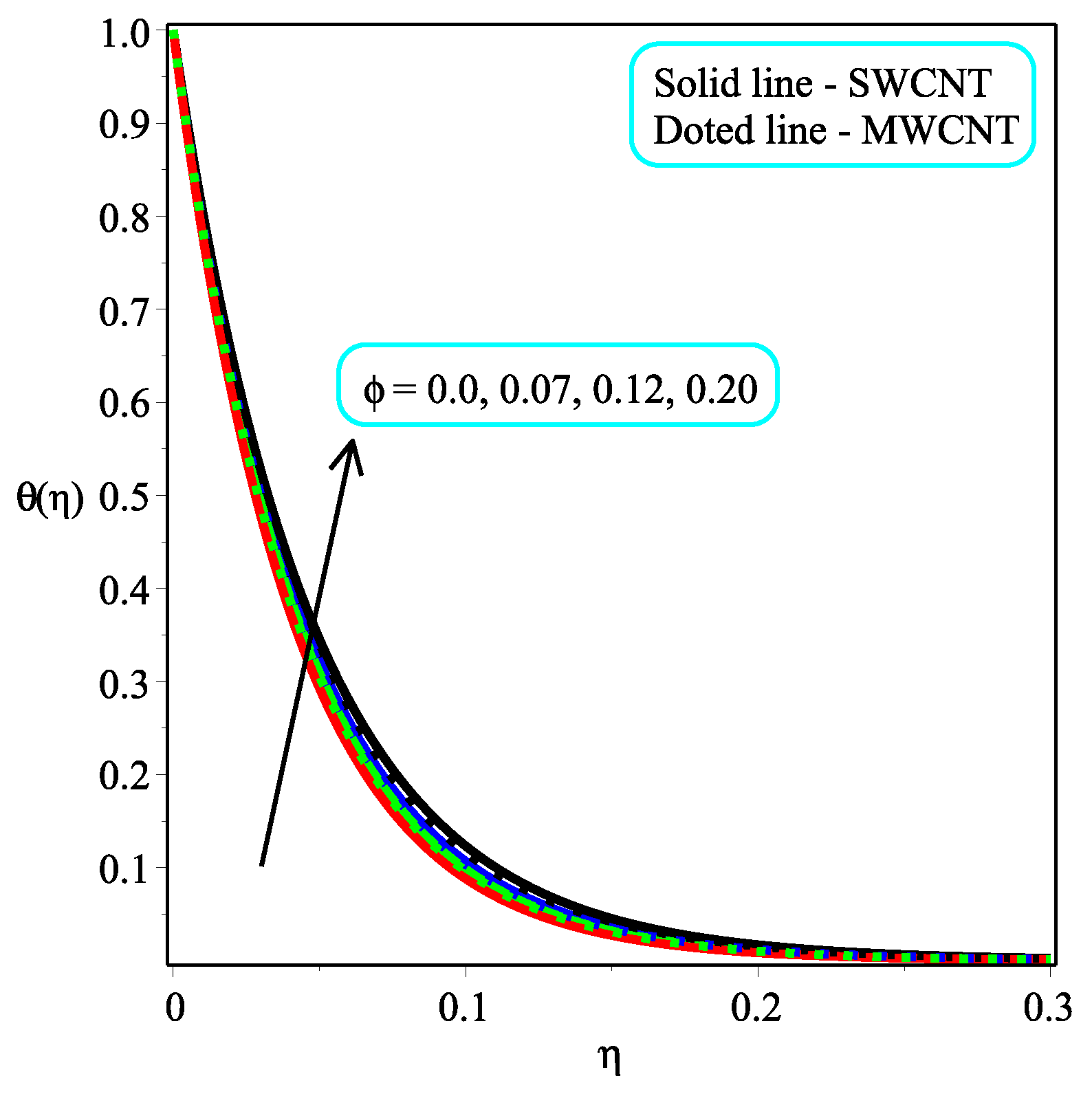
- It is examined that higher temperature distribution occurs in the case of a multi-walled CNT-based fluid as compared to a single-walled CNT-based fluid.
Author Contributions
Funding
Institutional Review Board Statement
Informed Consent Statement
Data Availability Statement
Conflicts of Interest
Nomenclature
| Magnetic field (Nm/A) | |
| Stress tensor element | |
| Strain tensor fraction | |
| Fluid’s yield stress | |
| Subscript for nanofluid | |
| Plastic dynamic viscosity of non-Newtonian fluid | |
| , | Critical values |
| x, y | Coordinates |
| Velocity components (m/s) | |
| Casson parameter | |
| Surface shrinking velocity (m/s) | |
| Wall mass transport parameter | |
| Electrical conductivity of nanofluid (S/m) | |
| Nanofluid density (Kg/) | |
| Carbon nanotube fluid | |
| Thermal conductivity of nanofluid (W/mK) | |
| Specific heat capacity (J/KgK) | |
| Density of base fluid (Kg/ | |
| Thermal conductivity of base fluid (W/mK) | |
| Solid volume fraction | |
| Suction/injection parameter | |
| Hartman number | |
| , , | Constants |
| Specific heat capacity of nanofluid (J/KgK) | |
| Radiation parameter | |
| N | Power law index |
| Radiative heat flux | |
| T | Temperature (K) |
| Sheet temperature (K) | |
| Free stream temperature (K) | |
| Stefan’s constant | |
| Mass absorption coefficient | |
| Thermal diffusivity /s) | |
| Prandtl number | |
| M | Confluent hyper-geometric function |
| Skin friction coefficient | |
| Stress at wall (N/ | |
| Reynolds number | |
| Nusselt number |
References
- Walvekar, R.; Faris, I.A.; Khalid, M. Thermal conductivity of carbon nanotube nanofluid—Experimental and theoretical study. Heat Transf. Res. 2012, 41, 145–163. [Google Scholar] [CrossRef]
- Phan, N.M.; Bui, H.T.; Nguyen, M.H.; Phan, H.K. Carbon-nanotube-based liquids: A new class of nanomaterials and their applications. Adv. Nat. Sci. Nanosci. Nanotechnol. 2014, 5, 015014. [Google Scholar] [CrossRef]
- Rafique, K.; Anwar, M.I.; Misiran, M.; Khan, I.; Alharbi, S.; Thounthong, P.; Nisar, K. Numerical solution of casson nanofluid flow over a non-linear inclined surface with soret and dufour effects by keller-box method. Front. Phys. 2019, 7, 139. [Google Scholar] [CrossRef]
- Choi, S.U.; Eastman, J.A. Enhancing Thermal Conductivity of Fluids with Nanoparticles; Technical Report; Argonne National Lab. (ANL): Argonne, IL, USA, 1995. [Google Scholar]
- Siddique, I.; Sadiq, K.; Jaradat, M.M.; Ali, R.; Jarad, F. Engine oil based MoS2 Casson nanofluid flow with ramped boundary conditions and thermal radiation through a channel. Case Stud. Therm. Eng. 2022, 35, 102118. [Google Scholar] [CrossRef]
- Mahato, R.; Das, M.; Sen, S.; Shaw, S. Entropy generation on unsteady stagnation-point Casson nanofluid flow past a stretching sheet in a porous medium under the influence of an inclined magnetic field with homogeneous and heterogeneous reactions. Heat Transf. 2022, 51, 5723–5747. [Google Scholar] [CrossRef]
- Ishtiaq, B.; Nadeem, S. Theoretical analysis of Casson nanofluid over a vertical exponentially shrinking sheet with inclined magnetic field. Waves Random Complex Media 2022, 1–17. [Google Scholar] [CrossRef]
- Qing, J.; Bhatti, M.M.; Abbas, M.A.; Rashidi, M.M.; Ali, M.E.S. Entropy generation on MHD Casson nanofluid flow over a porous stretching/shrinking surface. Entropy 2016, 18, 123. [Google Scholar] [CrossRef]
- Souayeh, B.; Reddy, M.G.; Sreenivasulu, P.; Poornima, T.; Rahimi-Gorji, M.; Alarifi, I.M. Comparative analysis on non-linear radiative heat transfer on MHD Casson nanofluid past a thin needle. J. Mol. Liq. 2019, 284, 163–174. [Google Scholar] [CrossRef]
- Haq, R.U.; Nadeem, S.; Khan, Z.H.; Okedayo, T.G. Convective heat transfer and MHD effects on Casson nanofluid flow over a shrinking sheet. Cent. Eur. J. Phys. 2014, 12, 862–871. [Google Scholar] [CrossRef]
- Mustafa, M.; Khan, J.A. Model for flow of Casson nanofluid past a non-linearly stretching sheet considering magnetic field effects. AIP Adv. 2015, 5, 077148. [Google Scholar] [CrossRef] [Green Version]
- Alwawi, F.A.; Alkasasbeh, H.T.; Rashad, A.; Idris, R. MHD natural convection of Sodium Alginate Casson nanofluid over a solid sphere. Results Phys. 2020, 16, 102818. [Google Scholar] [CrossRef]
- Nadeem, S.; Mehmood, R.; Akbar, N.S. Optimized analytical solution for oblique flow of a Casson-nano fluid with convective boundary conditions. Int. J. Therm. Sci. 2014, 78, 90–100. [Google Scholar] [CrossRef]
- Arif, M.; Kumam, P.; Kumam, W.; Khan, I.; Ramzan, M. A fractional model of Casson fluid with ramped wall temperature: Engineering applications of engine oil. Comput. Math. Methods 2021, 3, e1162. [Google Scholar] [CrossRef]
- Abolbashari, M.H.; Freidoonimehr, N.; Nazari, F.; Rashidi, M.M. Analytical modeling of entropy generation for Casson nano-fluid flow induced by a stretching surface. Adv. Powder Technol. 2015, 26, 542–552. [Google Scholar] [CrossRef]
- Yahya, A.U.; Salamat, N.; Huang, W.H.; Siddique, I.; Abdal, S.; Hussain, S. Thermal charactristics for the flow of Williamson hybrid nanofluid (MoS2 + ZnO) based with engine oil over a streched sheet. Case Stud. Therm. Eng. 2021, 26, 101196. [Google Scholar] [CrossRef]
- Mabood, F.; Shateyi, S. Multiple slip effects on MHD unsteady flow heat and mass transfer impinging on permeable stretching sheet with radiation. Model. Simul. Eng. 2019, 2019, 3052790. [Google Scholar] [CrossRef]
- Aly, E.H.; Pop, I. MHD flow and heat transfer over a permeable stretching/shrinking sheet in a hybrid nanofluid with a convective boundary condition. Int. J. Numer. Methods Heat Fluid Flow 2019, 29, 3012–3038. [Google Scholar] [CrossRef]
- Lund, L.A.; Omar, Z.; Khan, I.; Sherif, E.S.M. Dual solutions and stability analysis of a hybrid nanofluid over a stretching/shrinking sheet executing MHD flow. Symmetry 2020, 12, 276. [Google Scholar] [CrossRef]
- Yashkun, U.; Zaimi, K.; Bakar, N.A.A.; Ishak, A.; Pop, I. MHD hybrid nanofluid flow over a permeable stretching/shrinking sheet with thermal radiation effect. Int. J. Numer. Methods Heat Fluid Flow 2020, 31, 1014–1031. [Google Scholar] [CrossRef]
- Mahabaleshwar, U.; Vinay Kumar, P.; Sheremet, M. Magnetohydrodynamics flow of a nanofluid driven by a stretching/shrinking sheet with suction. SpringerPlus 2016, 5, 1901. [Google Scholar] [CrossRef] [Green Version]
- Sheikholeslami, M.; Hatami, M.; Ganji, D. Analytical investigation of MHD nanofluid flow in a semi-porous channel. Powder Technol. 2013, 246, 327–336. [Google Scholar] [CrossRef]
- Bhattacharyya, K.; Uddin, M.; Layek, G. Exact solution for thermal boundary layer in Casson fluid flow over permeable shrinking sheet with variable wall temperature and thermal radiation. Alex. Eng. J. 2016, 55, 1703–1712. [Google Scholar] [CrossRef]
- Haq, R.U.; Rashid, I.; Khan, Z. Effects of aligned magnetic field and CNTs in two different base fluids over a moving slip surface. J. Mol. Liq. 2017, 243, 682–688. [Google Scholar] [CrossRef]
- Aghamajidi, M.; Yazdi, M.; Dinarvand, S.; Pop, I. Tiwari-Das nanofluid model for magnetohydrodynamics (MHD) natural-convective flow of a nanofluid adjacent to a spinning down-pointing vertical cone. Propuls. Power Res. 2018, 7, 78–90. [Google Scholar] [CrossRef]
- Khan, U.; Zaib, A.; Pop, I.; Waini, I.; Ishak, A. MHD flow of a nanofluid due to a nonlinear stretching/shrinking sheet with a convective boundary condition: Tiwari–Das nanofluid model. Int. J. Numer. Methods Heat Fluid Flow 2022, 32, 3233–3258. [Google Scholar] [CrossRef]
- Rashid, I.; Sagheer, M.; Hussain, S. Entropy formation analysis of MHD boundary layer flow of nanofluid over a porous shrinking wall. Phys. A Stat. Mech. Its Appl. 2019, 536, 122608. [Google Scholar] [CrossRef]
- Rashid, I.; Haq, R.U.; Al-Mdallal, Q.M. Aligned magnetic field effects on water based metallic nanoparticles over a stretching sheet with PST and thermal radiation effects. Phys. E Low-Dimens. Syst. Nanostruct. 2017, 89, 33–42. [Google Scholar] [CrossRef]
- Rashid, I.; Haq, R.U.; Khan, Z.; Al-Mdallal, Q.M. Flow of water based alumina and copper nanoparticles along a moving surface with variable temperature. J. Mol. Liq. 2017, 246, 354–362. [Google Scholar] [CrossRef]
- Khan, M.; Sarfraz, M.; Ahmed, A.; Malik, M.; Alqahtani, A.S. Study of engine-oil based CNT nanofluid flow on a rotating cylinder with viscous dissipation. Phys. Scr. 2021, 96, 075005. [Google Scholar] [CrossRef]
- Giri, S.S.; Das, K.; Kundu, P.K. Influence of nanoparticle diameter and interfacial layer on magnetohydrodynamic nanofluid flow with melting heat transfer inside rotating channel. Math. Methods Appl. Sci. 2021, 44, 1161–1175. [Google Scholar] [CrossRef]
- Hussanan, A.; Khan, I.; Gorji, M.R.; Khan, W.A. CNTS-water–based nanofluid over a stretching sheet. BioNanoScience 2019, 9, 21–29. [Google Scholar] [CrossRef]


| Item | Name | |||
|---|---|---|---|---|
| Host Fluid | Engine oil | 884 | 1910 | 0.144 |
| SWCNT | 2600 | 425 | 6600 | |
| Nanoparticles | MWCNT | 1600 | 796 | 3000 |
| SWCNT | MWCNT | |||
|---|---|---|---|---|
| 0 | 0.2 | 3 | 2.316561177 | 2.316561177 |
| 0.09 | 2.165881457 | 2.003404391 | ||
| 0.14 | 2.050451725 | 1.830416322 | ||
| 0.20 | 1.889865256 | 1.626434980 | ||
| 0.1 | 0.2 | 3 | 2.144364785 | 1.968666416 |
| 0.4 | 2.165069733 | 1.990956551 | ||
| 0.6 | 2.185436595 | 2.012826468 | ||
| 0.8 | 2.205481411 | 2.034299073 | ||
| 0.1 | 0.2 | 2.5 | 1.881661396 | 2.034299073 |
| 3.5 | 2.415525397 | 2.211777817 | ||
| 4.5 | 2.975599453 | 2.714870113 | ||
| 5.5 | 3.551219031 | 3.232940895 |
| N | SWCNT | MWCNT | |||
|---|---|---|---|---|---|
| 0.2 | 0.1 | 2 | 1 | 62.46294101 | 65.67768785 |
| 0.4 | 62.46340335 | 65.67816046 | |||
| 0.6 | 62.46385308 | 65.67861805 | |||
| 0.8 | 62.46429066 | 65.67906178 | |||
| 0.2 | 0 | 2 | 1 | 127.5753320 | 127.5753320 |
| 0.09 | 66.30454502 | 69.47237912 | |||
| 0.14 | 49.96946560 | 53.20004770 | |||
| 0.20 | 36.98735855 | 39.99738167 | |||
| 0.2 | 0.1 | 1 | 1 | 62.79765517 | 66.01305649 |
| 2 | 62.46294101 | 65.67768785 | |||
| 3 | 62.12468837 | 65.33892386 | |||
| 4 | 61.78278446 | 64.99665998 | |||
| 0.2 | 0.1 | 2 | 1 | 62.46294101 | 65.67768785 |
| 2 | 48.11850998 | 50.14347211 | |||
| 3 | 39.06492988 | 40.48097101 | |||
| 4 | 32.83111149 | 33.89048821 |
| Bhattacharyya et al. [23] | Present Results | ||
|---|---|---|---|
| 0.5 | 3.5 | 0.66667 | 0.666666666 |
| 1 | 4 | 1.70711 | 1.707106781 |
| 2 | 4.5 | 2.75831 | 2.758305739 |
| 5 | 5 | 3.95602 | 3.956017087 |
Publisher’s Note: MDPI stays neutral with regard to jurisdictional claims in published maps and institutional affiliations. |
© 2022 by the authors. Licensee MDPI, Basel, Switzerland. This article is an open access article distributed under the terms and conditions of the Creative Commons Attribution (CC BY) license (https://creativecommons.org/licenses/by/4.0/).
Share and Cite
Rashid, I.; Zubair, T.; Asjad, M.I.; Tag-Eldin, E.M. The Influence of Aligned MHD on Engine Oil-Based Casson Nanofluid with Carbon Nanotubes (Single and Multi-Wall) Passing through a Shrinking Sheet with Thermal Radiation and Wall Mass Exchange. Micromachines 2022, 13, 1501. https://doi.org/10.3390/mi13091501
Rashid I, Zubair T, Asjad MI, Tag-Eldin EM. The Influence of Aligned MHD on Engine Oil-Based Casson Nanofluid with Carbon Nanotubes (Single and Multi-Wall) Passing through a Shrinking Sheet with Thermal Radiation and Wall Mass Exchange. Micromachines. 2022; 13(9):1501. https://doi.org/10.3390/mi13091501
Chicago/Turabian StyleRashid, Irfan, Tamour Zubair, Muhammad Imran Asjad, and Elsayed M. Tag-Eldin. 2022. "The Influence of Aligned MHD on Engine Oil-Based Casson Nanofluid with Carbon Nanotubes (Single and Multi-Wall) Passing through a Shrinking Sheet with Thermal Radiation and Wall Mass Exchange" Micromachines 13, no. 9: 1501. https://doi.org/10.3390/mi13091501