

Design of 4 × 4 Low-Profile Antenna Array for CubeSat Applications


Abstract
:1. Introduction
2. Antenna Design Methodology
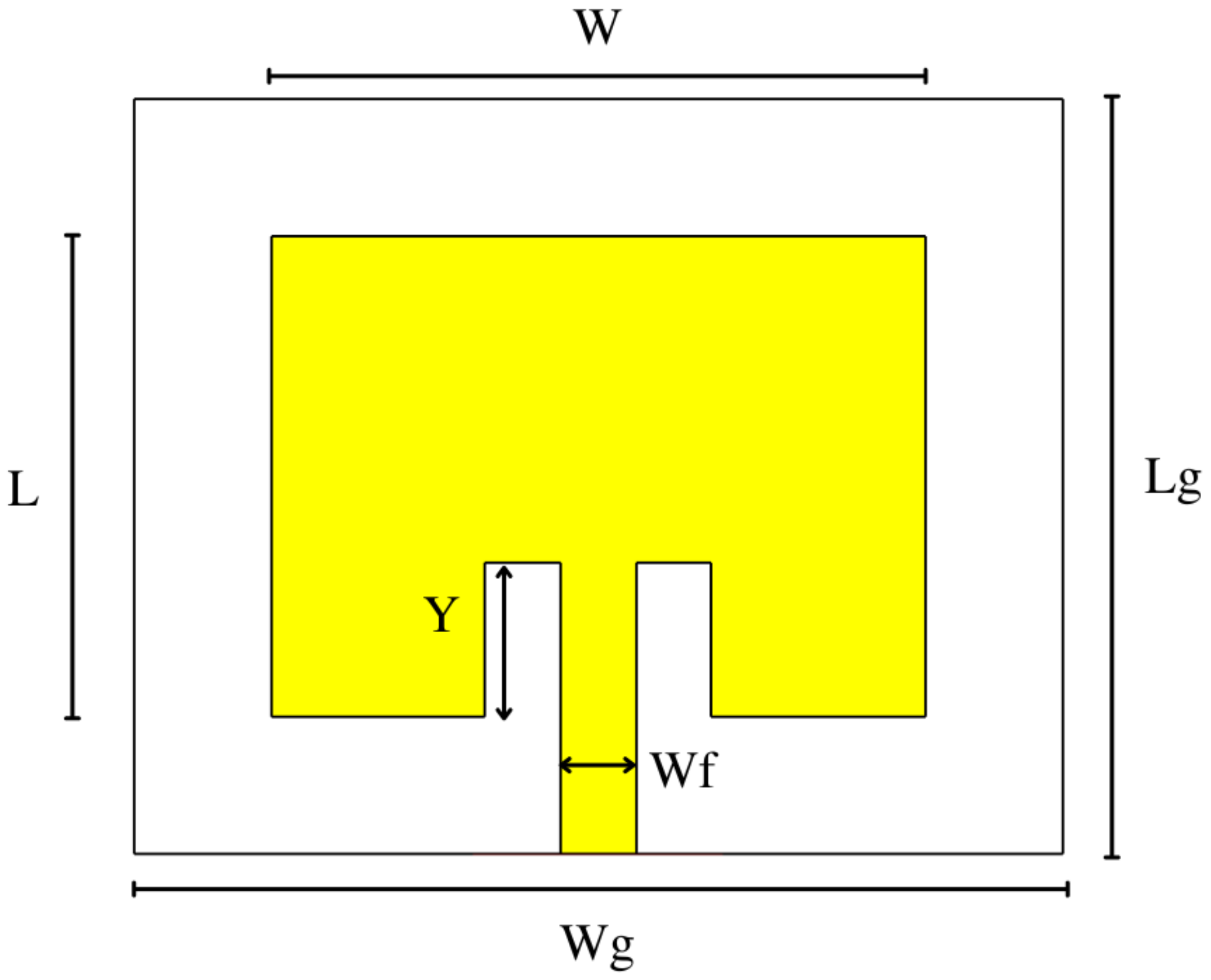
2.1. Antenna Element Design
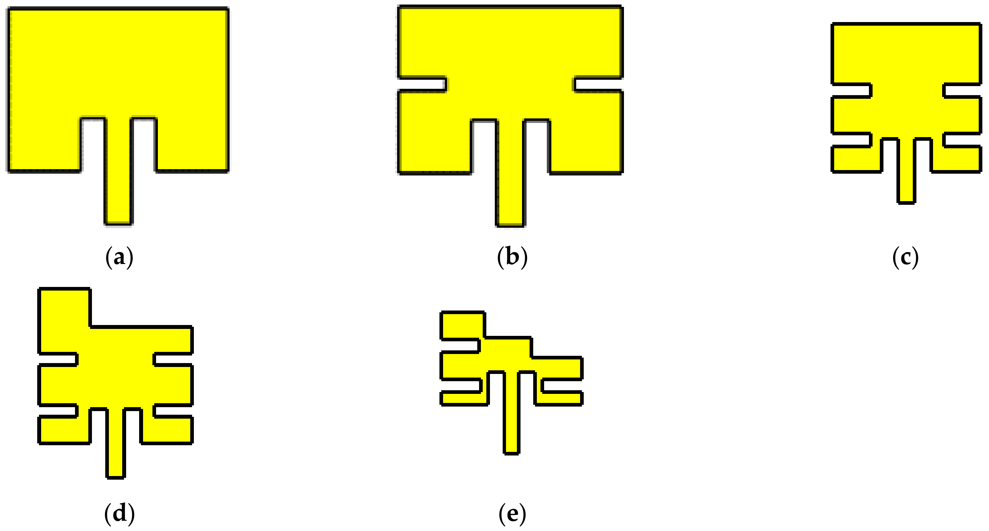
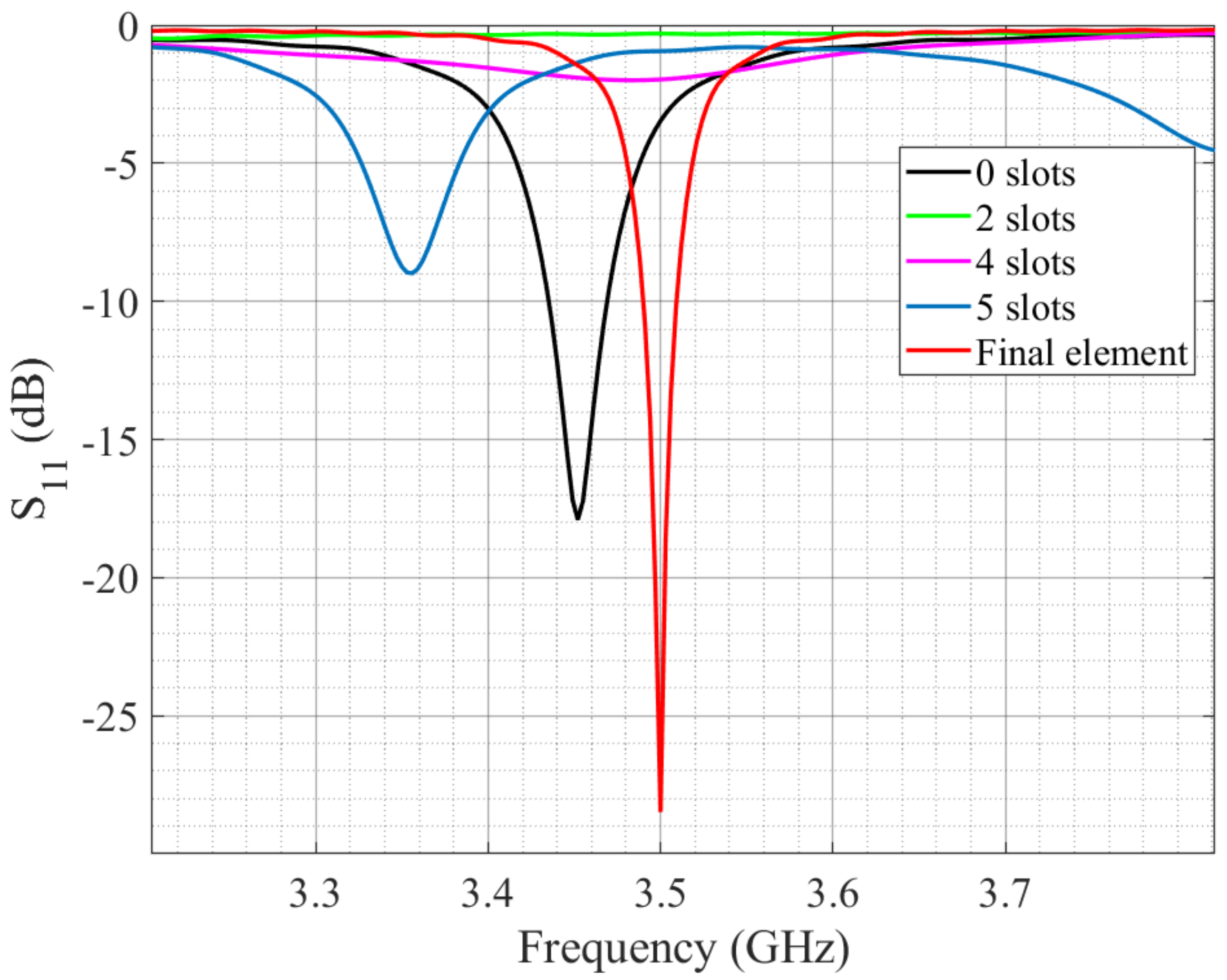
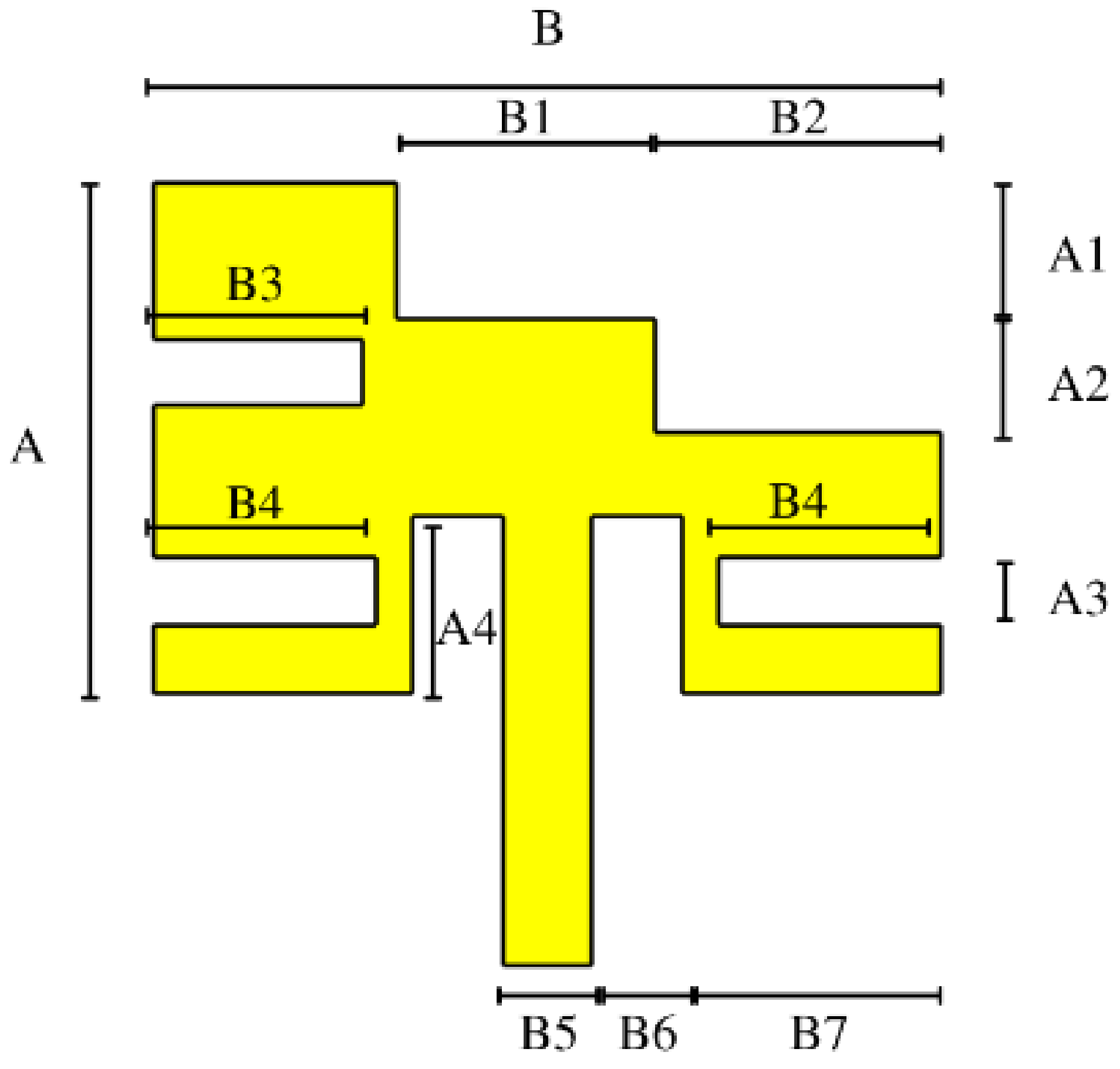
2.2. Antenna Element Miniaturization
2.3. Antenna Array Design
3. Research Results
4. Conclusions
Author Contributions
Funding
Institutional Review Board Statement
Informed Consent Statement
Data Availability Statement
Conflicts of Interest
References
- Fidler, F.; Knapek, M.; Horwath, J.; Leeb, W.R. Optical communications for high-altitude platforms. IEEE J. Sel. Top. Quantum Electron. 2010, 16, 1058–1070. [Google Scholar] [CrossRef]
- Mirza, J.; Atieh, A.; Menhas, M.I.; Ghafoor, S.; Magam, M.; Jamal, L.; Mitu Sheikh, S.I.; Qureshi, K.K. Design of an efficient thulium-doped fiber amplifier for dual-hop earth to satellite optical wireless links. Ain Shams Eng. J. 2022, in press. [CrossRef]
- Rycroff, M.; Crosby, N. Smaller Satellites: Bigger Business? Concepts, Applications, and Markets for Micro/Nanosatellites in a New Information World, 1st ed.; Springer Science + Business Media: Dordrecht, The Netherlands, 2002. [Google Scholar]
- Hank Heidt, H.; Puig-Suari, J.; Moore, A.S.; Nakasuka, S. CubeSat: A new generation of picosatellite for education and industry low-cost space experimentation. In Proceedings of the 14th Annual/USU Conference on Small Satellites, Logan, UT, USA, 21–24 August 2000. [Google Scholar]
- California Polytechnic State University. CubeSat Design Specification. Available online: https://www.cubesat.org/cubesatinfo (accessed on 12 December 2022).
- Tang, H.; Yang, N.; Zhang, Z.; Du, Z.; Shen, J. 5G NR and Enhancements, 1st ed.; Elsevier: Amsterdam, The Netherlands, 2021. [Google Scholar]
- Vaezi, M.; Azari, A.; Khosravirad, S.R.; Shirvanimoghaddam, M.; Azari, M.M.; Chasaki, D.; Popovski, P. Cellular, wide—Area, and Non-Terrestrial IoT: A survey on 5G advances and the road toward 6G. IEEE Comms. Surv. Tutor. 2022, 24, 1117–1174. [Google Scholar] [CrossRef]
- Abulgasem, S.; Tubbal, F.; Raad, R.; Theoharis, P.I.; Lu, S.; Iranmanesh, S. Antenna designs for CubeSats: A review. IEEE Access 2021, 9, 45289–45324. [Google Scholar] [CrossRef]
- Mizuno, T.J.; Roque, J.D.; Murakami, B.T.; Yoneshige, L.K.; Shiroma, G.S.; Miyamoto, R.Y.; Shiroma, W.A. Antennas for distributed nanosatellite networks. In Proceedings of the IEEE/ACES International Conference on Wireless Communications and Applied Computational Electromagnetics, Honolulu, HI, USA, 3–7 April 2005; pp. 606–609. [Google Scholar]
- Leao, T.F.C.; Mooney-Chopin, V.; Trueman, C.W.; Gleason, S. Design and implementation of a diplexer and a dual-band VHF/UHF antenna for nanosatellites. IEEE Antennas Wireless Propag. Lett. 2013, 12, 1098–1101. [Google Scholar] [CrossRef]
- Prodoningrum, R.T.; Wijanto, H.; Prasetyo, A.D. Antenna deployment for automatic packet reporting system of nanosatellite using global positioning system as a height sensor. In Proceedings of the International Conference on Quality in Research (QiR), Lombok, Indonesia, 10–13 August 2015; pp. 1098–1101. [Google Scholar]
- Bellion, A.; Elis, K.; De Gaetano, S. New compact S-band antenna for nanosatellite telemetry and telecommand applications—EyeSat program. In Proceedings of the 10th European Conference on Antennas and Propagation (EuCAP), Davos, Switzerland, 10–15 April 2016; pp. 1–5. [Google Scholar]
- Huang, T.; Reveles, J.R.; Gurusamy, V.; Harrington, Q.; Fraux, V. An innovative deployable VHF/UHF helical antenna for nanosatellites. In Proceedings of the 13th European Conference on Antennas and Propagation (EuCAP), Krakow, Poland, 31 March–5 April 2019; pp. 1–4. [Google Scholar]
- El Hammoumi, M.; Tubbal, F.; El Amrani El Idrissi, N.; Raad, R.; Ioannis Theoharis, P.; Lalbakhsh, A.; Abulgasem, S. A wideband 5G CubeSat patch antenna. IEEE J. Miniat. Air Space Syst. 2022, 3, 47–52. [Google Scholar] [CrossRef]
- El Hammoumi, M.; El Amrani El Idrissi, N.; Raad, R.; Ioannis Theoharis, P.; Tubbal, F.; Abulgasem, S. Ultra Wideband dual circularly polarized patch antenna for 5G and CubeSat applications. In Proceedings of the 9th International Conference on Wireless Networks and Mobile Communications (WINCOM), Rabat, Morocco, 26–29 October 2022; pp. 1–6. [Google Scholar]
- El Hammoumi, M.; El Amrani El Idrissi, N.; Raad, R.; Ioannis Theoharis, P.; Tubbal, F. A wideband compact patch antenna for Ka-band and CubeSat applications. In Proceedings of the 15th International Conference on Signal Processing and Communication Systems (ICSPCS), Sydney, NSW, Australia, 13–15 December 2021; pp. 1–5. [Google Scholar]
- Aswoyo, B.; Putra, A.H. High gain microstrip square patch array antenna 4 × 4 element 2.3 GHz for 5G communication in Indonesia. In Proceedings of the International Electronics Symposium (IES), Surabaya, Indonesia, 29–30 September 2021; pp. 102–107. [Google Scholar]
- Chand Ravi, K.; Kumar, J.; Elwi, T.A.; Mahdi Ali, M. Compact MIMO antenna for 5G Applications. In Proceedings of the IEEE ANDESCON, Barranquilla, Colombia, 16–19 November 2022; pp. 1–6. [Google Scholar]
- Gupta, V.; Prabhakar, S. Dual band micro-strip patch antennas for 5G sub 6 GHz smart mobile phone and C-band application. In Proceedings of the 2nd International Conference on Smart Electronics and Communication (ICOSEC), Trichy, India, 7–9 October 2021; pp. 426–434. [Google Scholar]
- Chen, X.; Wang, J.; Chang, L. Extremely low profile dual band microstrip patch antenna using electric coupling for 5G mobile terminal application. IEEE Trans. Antennas Propag. 2022. [Google Scholar] [CrossRef]
- Saxena, N. An air substrate microstrip patch antenna for N77 band application. In Proceedings of the 2nd Asian Conference on Innovation in Technology (ASIANCON), Ravet, India, 26–28 August 2022; pp. 1–3. [Google Scholar]
- Gao, Y.; Wang, J.; Wang, X.; Wei, M. A low profile broadband multimode patch antenna for 5G mobile applications. IEEE Antennas Wirel. Propag. Lett. 2022, 1–5. [Google Scholar] [CrossRef]
- Hasan, M.M.; Rahman, R.; Shaikh, R.; Alam, I.; Islam, M.A.; Alam, M.S. Design and analysis of elliptical microstrip patch antenna at 3.5 GHz for 5G applications. In Proceedings of the IEEE Region 10 Symposium (TENSYMP), Dhaka, Bangladesh, 5–7 June 2020; pp. 981–984. [Google Scholar]
- Magalhães, M.P.; Heckler, M.V.T.; Mota, J.C.M.; Sombra, A.S.B.; Moreira, E.C. Design and analysis of microstrip antenna arrays for meteorological nano-satellites for UHF uplink. In Proceedings of the International Telecommunications Symposium (ITS), Sau Paulo, Brazil, 17–20 August 2014; pp. 1–5. [Google Scholar]
- Vieira, J.M.; Yoshimoto, E.; Ferreira, F.G.; Pereira, V.M.; Heckler, M.V.T. UHF and S-band antenna arrays for nano-satellite-based data-relay. In Proceedings of the 12th European Conference on Antennas and Propagation (EuCAP 2018), London, UK, 9–13 April 2018; pp. 1–5. [Google Scholar]
- Alam, T.; Islam, M.T.; Ullah, M.A.; Rahmatillah, R.; Aheieva, K.; Lap, C.C.; Cho, M. Design and compatibility analysis of a solar panel integrated UHF antenna for nanosatellite space mission. PLoS ONE 2018, 13, e0205587. [Google Scholar] [CrossRef] [PubMed]
- Benyamin, S.O.; Wijanto, H.; Prabowo, V.S.W.; Prananditya, H.; Oktaviani, S.M. Design and Characterization Of Rectangular Array Microstrip Antenna For Cubesat S-Band Transmitter. In Proceedings of the 3rd International Conference on Information and Communications Technology (ICOIACT), Yogyakarta, Indonesia, 24–25 November 2020; pp. 476–481. [Google Scholar]
- Arnaud, E.; Menudier, C.; Fouany, J.; Monediere, T.; Thevenot, M. X-band compact dual circularly polarized isoflux antenna for nanosatellite applications. Int. J. Microw. Wirel. Technol. 2017, 9, 1509–1516. [Google Scholar] [CrossRef] [Green Version]
- Arnaud, E.; Siblini, A.; Bellion, A.; Jecko, B. Experimental validation of an isoflux Earth coverage with a bimode ARMA antenna on a nanosatellite. Int. J. Microw. Wirel. Technol. 2020, 12, 66–74. [Google Scholar] [CrossRef]
- Hashim, I.S.M.; Al-Hourani, A.; Wayne Rowe, S.T.; Scott, J.R. Adaptive X-band satellite antenna for Internet-of-Things (IoT) over satellite applications. In Proceedings of the 13th International Conference on Signal Processing and Communication Systems (ICSPCS), Gold Coast, QLD, Australia, 16–18 December 2019; pp. 1–7. [Google Scholar]
- Squadrito, P.; Zhang, S.; Pedersen, J.F. High gain K-band patch antenna for low earth orbit interlink between nanosatellites. In Proceedings of the 12th European Conference on Antennas and Propagation (EuCAP 2018), London, UK, 9–13 April 2018; pp. 1–4. [Google Scholar]
- Balanis, C.A. Microstrip Antennas. In Antenna Theory. Analysis and Design, 3rd ed.; John Wiley & Sons, Inc.: Hoboken, NJ, USA, 2005; pp. 811–826. [Google Scholar]
- Stutzman, W.L.; Thiele, G.A. Antenna Theory and Design; John Wiley & Sons, Inc.: Hoboken, NJ, USA, 2012. [Google Scholar]
- Mishra, M.; Chaudhuri, S.; Kshetrimayum, R.S. Low mutual coupling four-port MIMO antenna array for 3.5 GHz WiMAX application. In Proceedings of the IEEE Region 10 Symposium (TENSYMP), Dhaka, Bangladesh, 5–7 June 2020; pp. 791–794. [Google Scholar]
- Rajeshkumar, V.; Raghavan, S. A compact CSRR loaded dual band microstrip patch antenna for wireless applications. In Proceedings of the IEEE International Conference on Computational Intelligence and Computing Research, Enathi, India, 26–28 December 2013; pp. 1–4. [Google Scholar]
- Wang, Y.; Piao, D. A dual-polarized antenna with pattern diversity based on a two-mode single-layer microstrip patch. In Proceedings of the IEEE MTT-S International Wireless Symposium (IWS), Chengdu, China, 6–10 May 2018; pp. 1–3. [Google Scholar]
- Chen, W.S.; Lin, Y.S. Design of 2 × 2 microstrip patch array antenna for 5G C-band access point applications. In Proceedings of the IEEE International Workshop on Electromagnetics: Applications and Student Innovation Competition (iWEM), Nagoya, Japan, 29–31 August 2018; pp. 1–2. [Google Scholar]
- Sajjad, H.; Sethi, W.T.; Zeb, K.; Mairaj, A. Microstrip patch antenna array at 3.8 GHz for WiMax and UAV applications. In Proceedings of the International Workshop on Antenna Technology: Small Antennas, Novel EM Structures and Materials, and Applications (iWAT), Sydney, NSW, Australia, 4–6 March 2014; pp. 107–110. [Google Scholar]
- Bouça, P.; Matos, J.N.; Cunha, S.R.; Carvalho, N.B. Low-profile aperture-coupled patch antenna array for CubeSat applications. IEEE Access 2020, 8, 20473–20479. [Google Scholar] [CrossRef]
- Harane, M.M.; Ammor, H. Design & development of 4 × 2 microstrip patch antenna array with circular polarized elements for satellite application. In Proceedings of the International Symposium on Advanced Electrical and Communication Technologies (ISAECT), Rabat, Morocco, 21–23 November 2018; pp. 1–4. [Google Scholar]
- Hussain, R.; Rao, A.S.; Aziz, A.; Khan, M.U.; Sharawi, M.S. Highly miniaturized folded-slot based MIMO antenna design for CubeSat applications. In Proceedings of the 16th European Conference on Antennas and Propagation (EuCAP), Madrid, Spain, 27 March–1 April 2022; pp. 1–3. [Google Scholar]
- Warren, P.A.; Steinbeck, J.W.; Minelli, R.J.; Mueller, C. Large, deployable S-band antenna for a 6U CubeSat. In Proceedings of the 29th Annual AIAA/USU Conference on Small Satellites, Logan, UT, USA, 8–13 August 2015; pp. 1–7. [Google Scholar]
- Figueroa Torres, C.A.; Medina Monroy, J.L.; Lobato Morales, H.; Chávez Pérez, R.A.; Calvillo Téllez, A. Microstrip circular antenna array design for CubeSat applications. Aristas J. Basic Appl. Sci. 2016, 9, 106–110. [Google Scholar]
- Figueroa Torres, C.A.; Medina Monroy, J.L.; Lobato Morales, H.; Chávez Pérez, R.A.; Calvillo Téllez, A. A microstrip antenna based on a standing-wave fractal geometry for CubeSat applications. Microw. Opt. Technol. Lett. 2016, 58, 2210–2214. [Google Scholar] [CrossRef]


| No. Slots | 0 | 2 | 4 | 5 | Final Element |
|---|---|---|---|---|---|
| Gain (dBi) | 5.344 | −7.706 | 2.595 | 1.993 | 1.493 |
| Size (λ) | 0.221 | 0.221 | 0.14 | 0.14 | 0.1352 |
| Parameters | A | A1 | A2 | A3 | A4 |
|---|---|---|---|---|---|
| Values (mm) | 7.5 | 2 | 1.67 | 1 | 2.6 |
| Values (λ) | 0.0875 | 0.0233 | 0.0194 | 0.0116 | 0.0303 |
| Parameters | B | B1 | B2 | B3 | B4 |
| Values (mm) | 11.592 | 3.8 | 4.2 | 3.0927 | 3.27 |
| Values (λ) | 0.1352 | 0.0443 | 0.049 | 0.0360 | 0.0381 |
| Parameters | B5 | B6 | B7 | ||
| Values (mm) | 1.32 | 1.32 | 3.8164 | ||
| Values (λ) | 0.0154 | 0.0154 | 0.0445 |
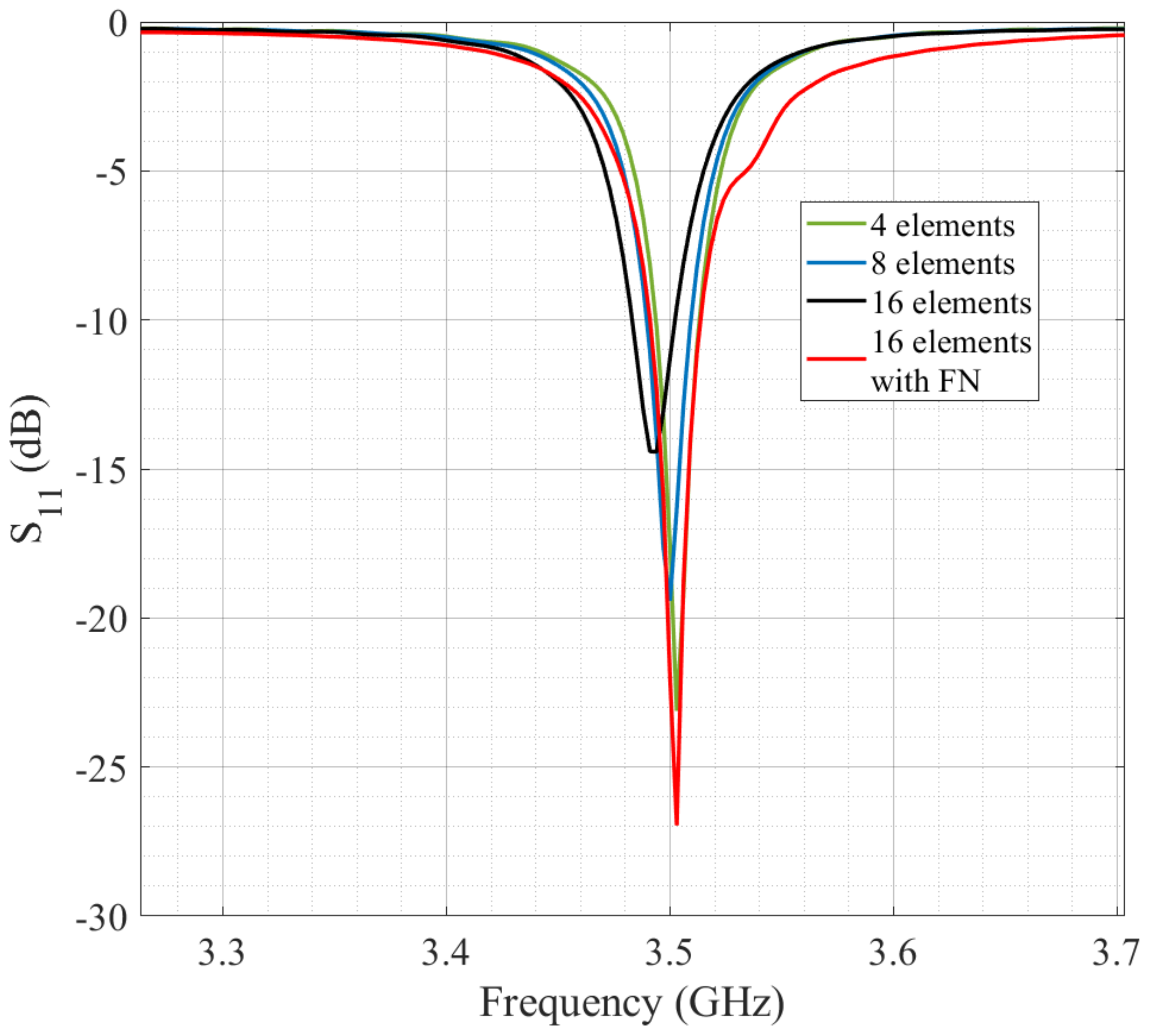
| No. Elements (N) | 4 | 8 | 16 | 16 |
|---|---|---|---|---|
| Feeding Network | Not included | Not included | Not included | Included |
| Gain (dBi) | 6.258 | 8.012 | 10.43 | 10.62 |
| Parameters | L | W | L1 | L2 | L3 | L4 | L5 | L6 |
|---|---|---|---|---|---|---|---|---|
| Values (mm) | 100 | 100 | 27.5 | 0.8 | 6.0174 | 0.995 | 26.7 | 0.8 |
| Values (λ) | 1.1666 | 1.1666 | 0.3208 | 0.0093 | 0.0702 | 0.0116 | 0.3115 | 0.0093 |
| Parameters | L7 | LA | LB | LC | LD | W1 | W2 | W3 |
| Values (mm) | 2.4 | 2.003 | 11.5 | 16 | 8 | 1.255 | 22.6917 | 0.935 |
| Values (λ) | 0.028 | 0.0233 | 0.1341 | 0.1866 | 0.0933 | 0.0146 | 0.2647 | 0.0109 |
| Parameters | W4 | W5 | W6 | W7 | WA | WB | WC | |
| Values (mm) | 3.315 | 0.65 | 12.6483 | 2.4 | 7.8371 | 15.674 | 3.3038 | |
| Values (λ) | 0.0386 | 0.0075 | 0.1475 | 0.028 | 0.0914 | 0.1828 | 0.0385 |
| Ref. | Design | Frequency | Bandwidth | Size | Material | Gain | Ports | Applications | CubeSat Structure |
|---|---|---|---|---|---|---|---|---|---|
| [30] | Phased array antenna. N = 16 | 8.047–8.737 GHz | 690 MHz | 100 mm × 100 mm 2.736 λ × 2.736 λ | Rogers RT Duroid 5880 and RO3010 | High gain Not provided | 1 | CubeSat | Not included |
| [34] | Printed monopole antenna. MIMO antenna array. N = 4. | 3.37–3.61 GHz | 240 MHz | 60 mm × 60 mm 0.7 λ × 0.7 λ | Rogers 5870 | Between 2.71 dBi and 2.83 dBi | 4 | WiMax | Not applied |
| [35] | Microstrip patch antenna. Element. | 3.54–3.65 GHz | 110 MHz | 30 mm × 30 mm 0.36 λ × 0.36 λ | FR4 | 3.85 dB | 1 | Wireless | Not applied |
| [36] | Circular microstrip patch antenna. Element. | 3.46–3.57 GHz | 110 MHz | 30 mm 0.35 λ | FR4 | Low gain Not provided | 2 | Mobile communication | Not applied |
| [37] | Microstrip patch antenna. Array N = 4. | 3.4–3.6 GHz | 200 MHz | 88.5 mm × 88.5 mm 1.003 λ × 1.003 λ | FR4 | 5.37 dBi | 1 | WiFi | Not applied |
| [38] | Microstrip patch antenna. Array N = 4. | 3.7693–3.8413 GHz | 72 MHz | Size >100 mm Size >1.26 λ | Rogers Duroid RT5880 | 13.2 dBi | 1 | WiMax and UAV | Not applied |
| [39] | Aperture Coupled Patch Antenna. Array N = 4. | 5.48–5.6 GHz | 120 MHz | 230 mm × 105 mm 4.21 λ × 0.84 λ | Astra MT77 | 12.4 dBi | 2 | CubeSat | Not included |
| [40] | Microstrip patch antenna. Array N = 8. | 11.13–12.78 GHz | 1.65 GHz | 30 mm × 60 mm 2.336 λ × 1.168 λ | FR4 | 9.37 dB | 1 | Satellite | Not included |
| [41] | Slot patch antenna. N = 2. | 430–514 MHz | 84 MHz | 100 mm × 100 mm 0.15 λ × 0.15 λ | Rogers RO4350 | Low gain Not provided | 2 | CubeSat | Not included |
| [42] | Microstrip patch antenna. Deployable Array N = 256 | 3.3–3.9 GHz | 600 MHz | Size >100 mm Size >1.15 λ | Not provided | 30.5 dBi | 1 | CubeSat | Not included |
| [43] | Circular microstrip patch antenna. Array N = 4. | 2.3–2.5 GHz | 200 MHz | 100 mm × 100 mm 0.8 λ × 0.8 λ | FR4 | 4.7 dBi | 1 | CubeSat | Not included |
| [44] | Fractal microstrip patch antenna. Element. | 2.3–2.5 GHz | 200 MHz | 72 mm × 72 mm 0.588 λ × 0.588 λ | FR4 | 3.5 dBi | 1 | CubeSat | Not included |
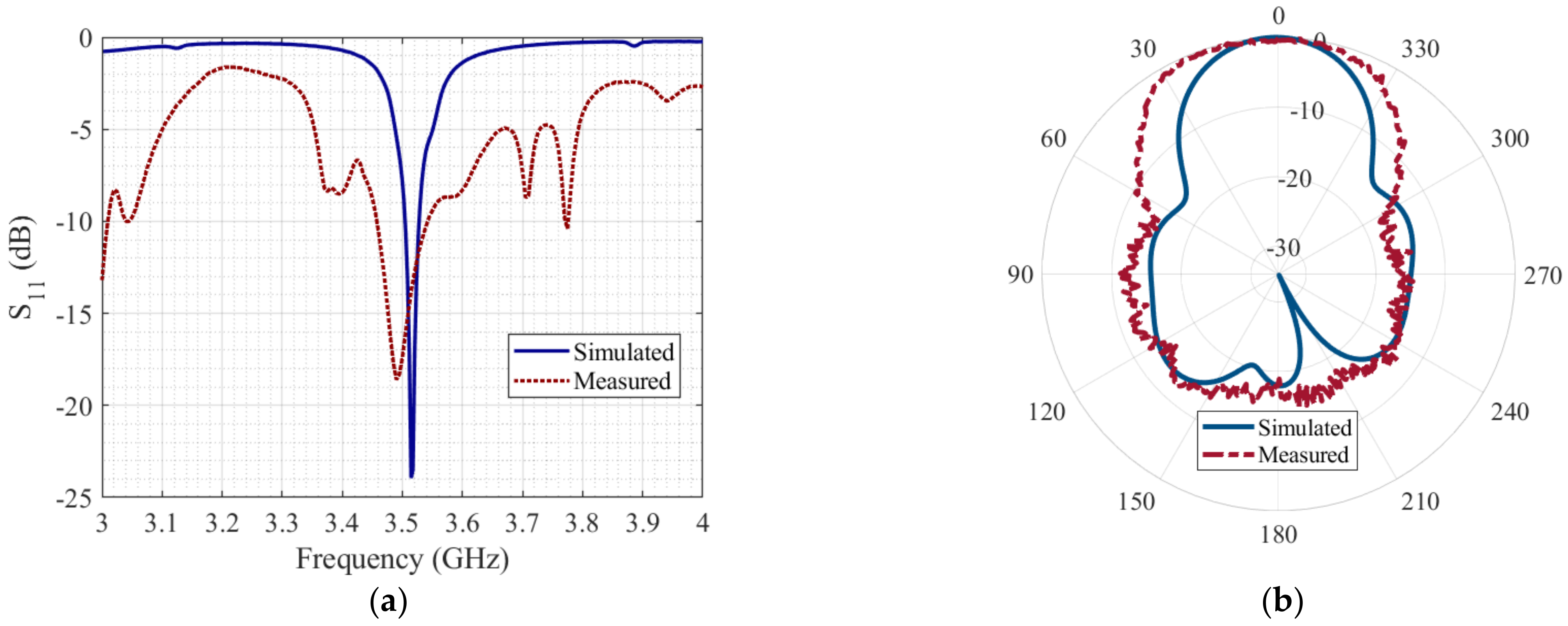
| This work | Microstrip patch antenna. Array N = 16 assembled on CubeSat. | 3.46–3.54 GHz | 80 MHz | 100 mm × 100 mm 1.1666 λ × 1.1666 λ | Rogers TMM10 | 8.03 dBi | 1 | CubeSat | Included |
Disclaimer/Publisher’s Note: The statements, opinions and data contained in all publications are solely those of the individual author(s) and contributor(s) and not of MDPI and/or the editor(s). MDPI and/or the editor(s) disclaim responsibility for any injury to people or property resulting from any ideas, methods, instructions or products referred to in the content. |
© 2023 by the authors. Licensee MDPI, Basel, Switzerland. This article is an open access article distributed under the terms and conditions of the Creative Commons Attribution (CC BY) license (https://creativecommons.org/licenses/by/4.0/).
Share and Cite
Jiménez, D.A.; Reyna, A.; Balderas, L.I.; Panduro, M.A. Design of 4 × 4 Low-Profile Antenna Array for CubeSat Applications. Micromachines 2023, 14, 180. https://doi.org/10.3390/mi14010180
Jiménez DA, Reyna A, Balderas LI, Panduro MA. Design of 4 × 4 Low-Profile Antenna Array for CubeSat Applications. Micromachines. 2023; 14(1):180. https://doi.org/10.3390/mi14010180
Chicago/Turabian StyleJiménez, Diana Alondra, Alberto Reyna, Luz Idalia Balderas, and Marco Antonio Panduro. 2023. "Design of 4 × 4 Low-Profile Antenna Array for CubeSat Applications" Micromachines 14, no. 1: 180. https://doi.org/10.3390/mi14010180
APA StyleJiménez, D. A., Reyna, A., Balderas, L. I., & Panduro, M. A. (2023). Design of 4 × 4 Low-Profile Antenna Array for CubeSat Applications. Micromachines, 14(1), 180. https://doi.org/10.3390/mi14010180