
Broadband Flexible Microstrip Antenna Array with Conformal Load-Bearing Structure
 , ,
, ,
Abstract
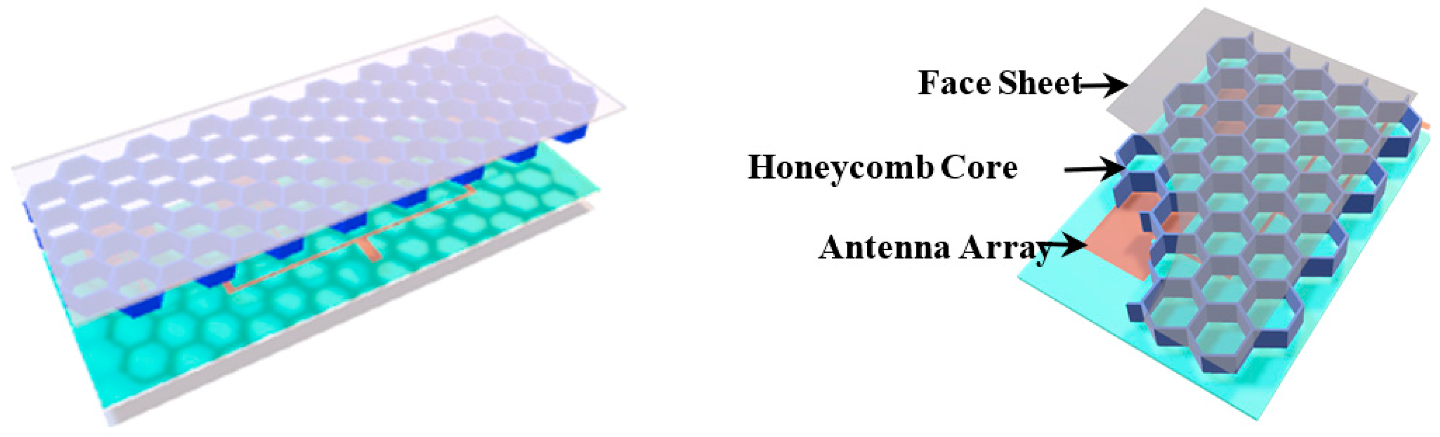
:1. Introduction
2. Antenna Design
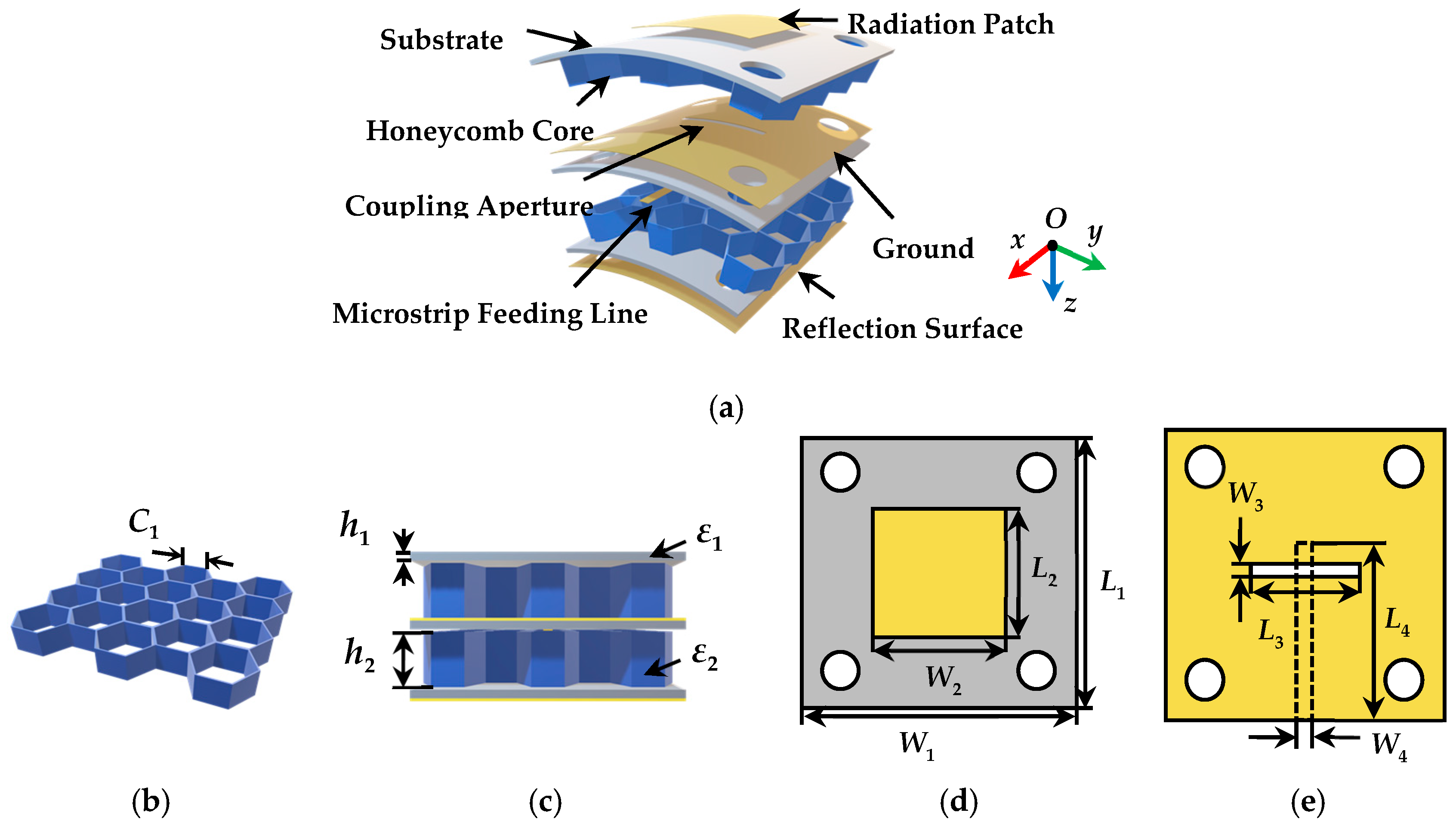
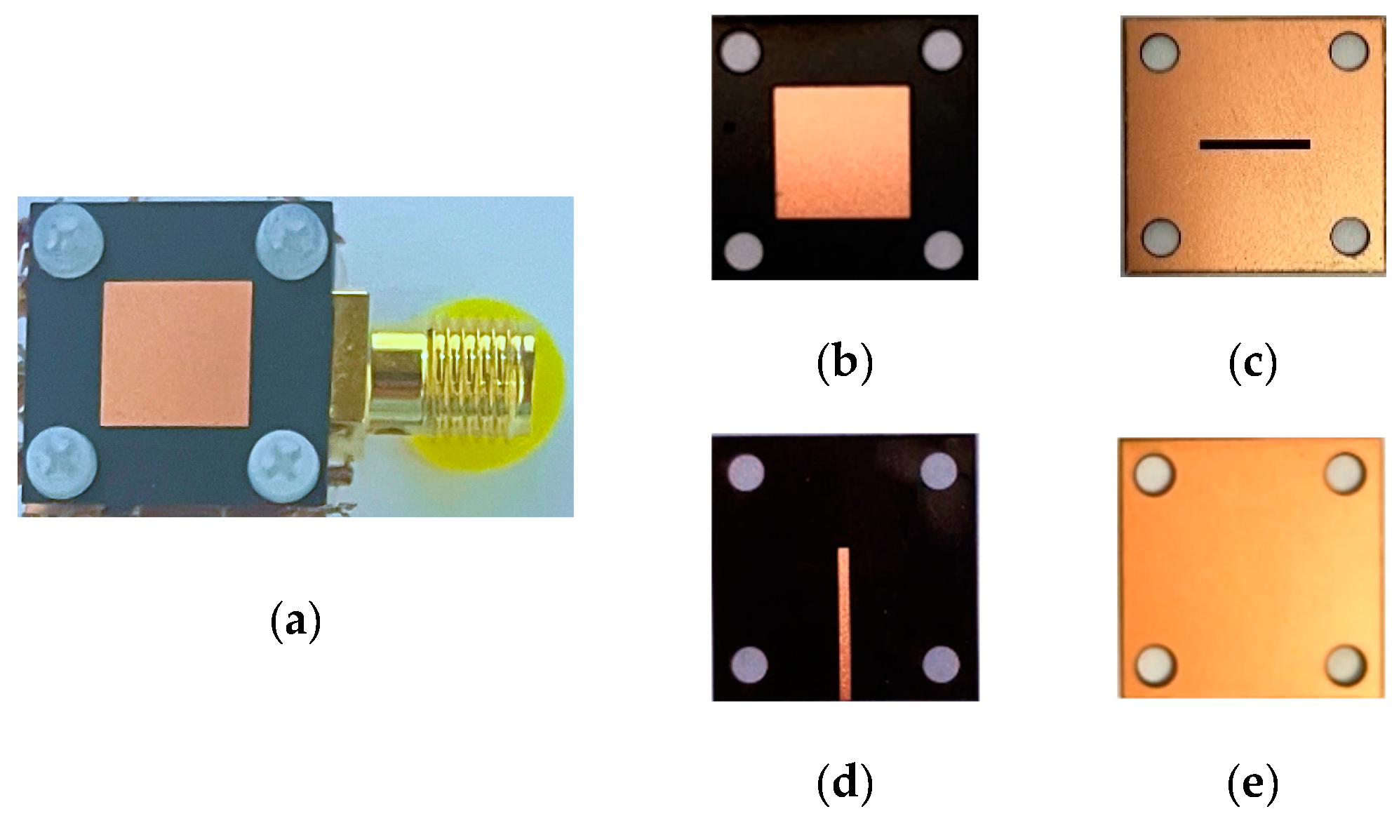
2.1. Antenna Element
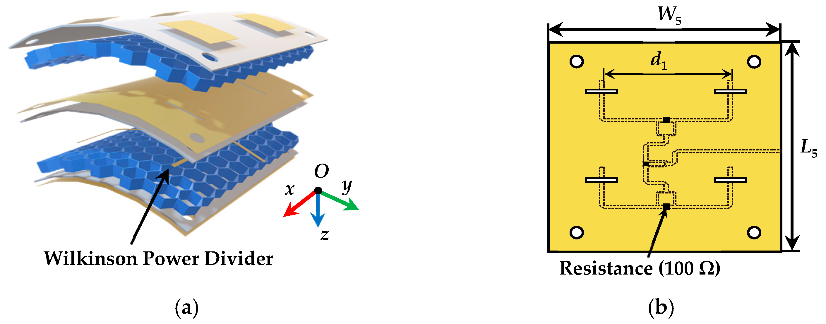
2.2. Antenna Array
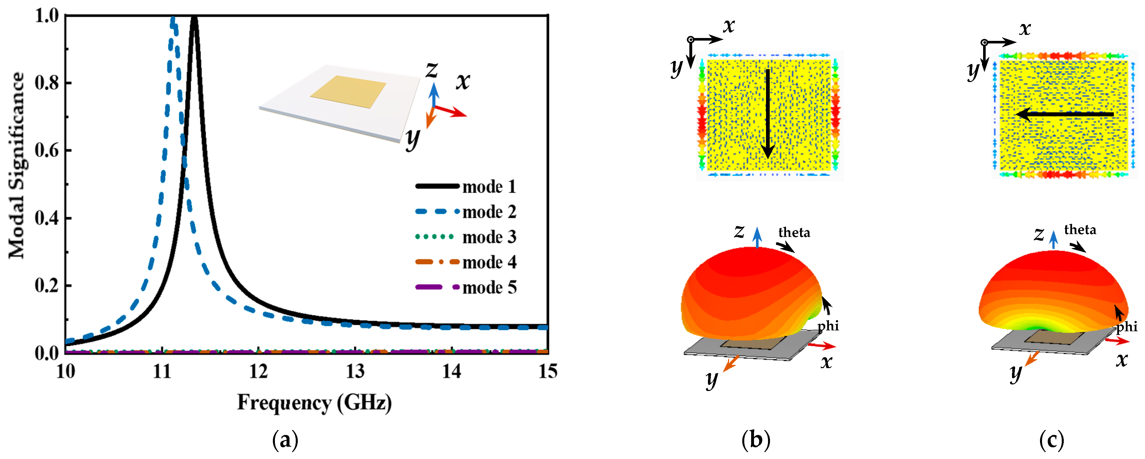
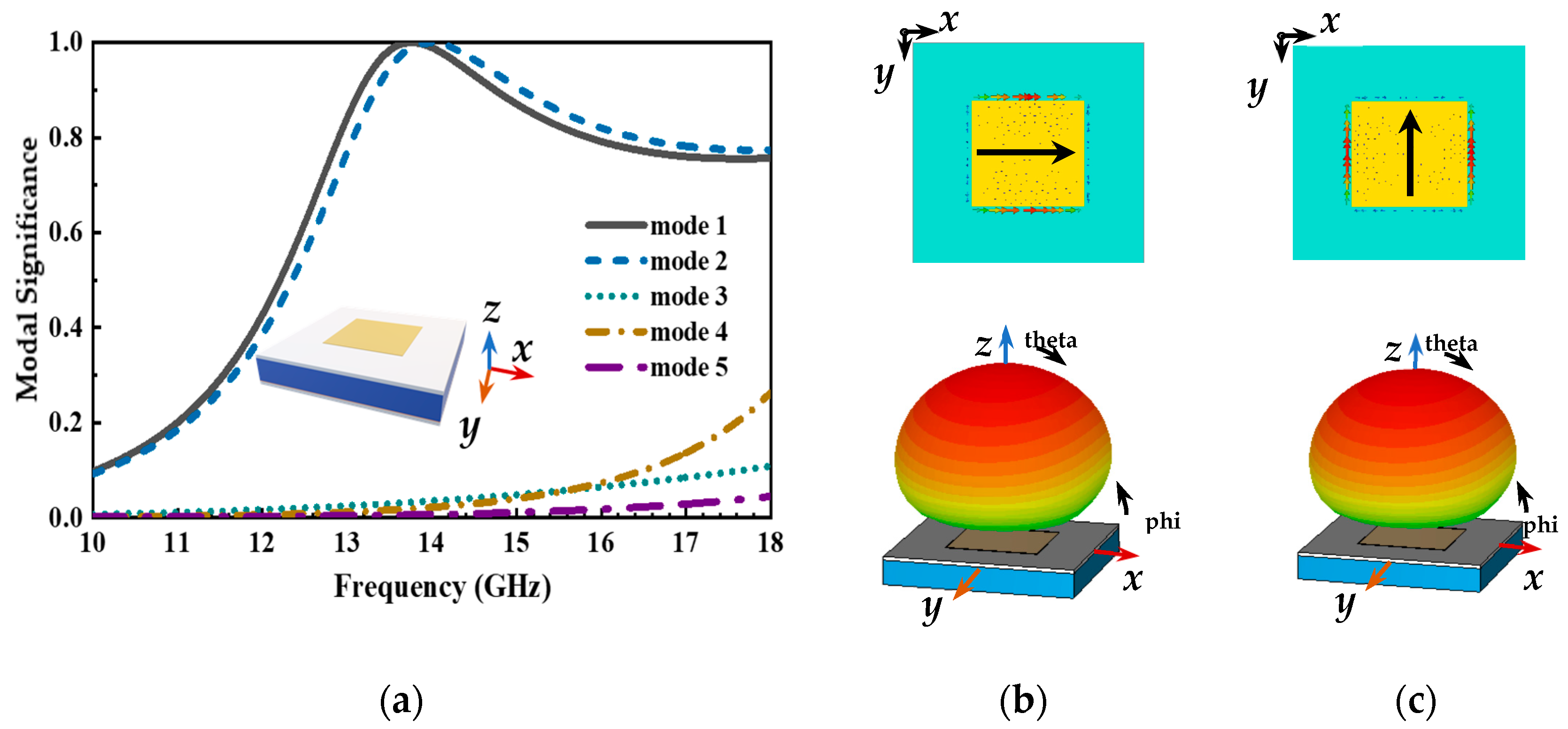
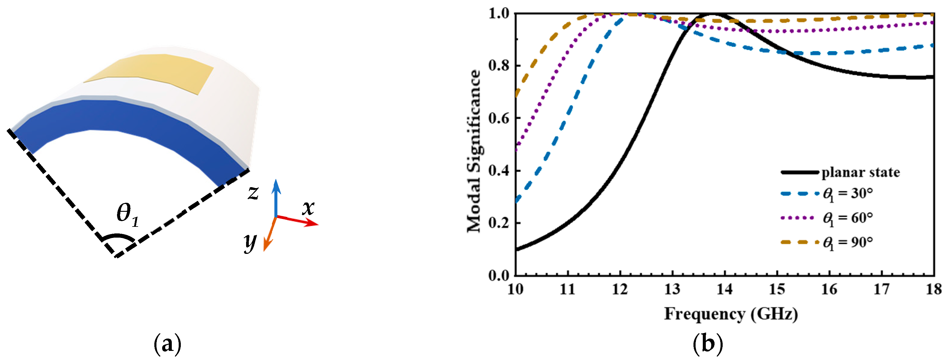
3. Theoretical Analysis
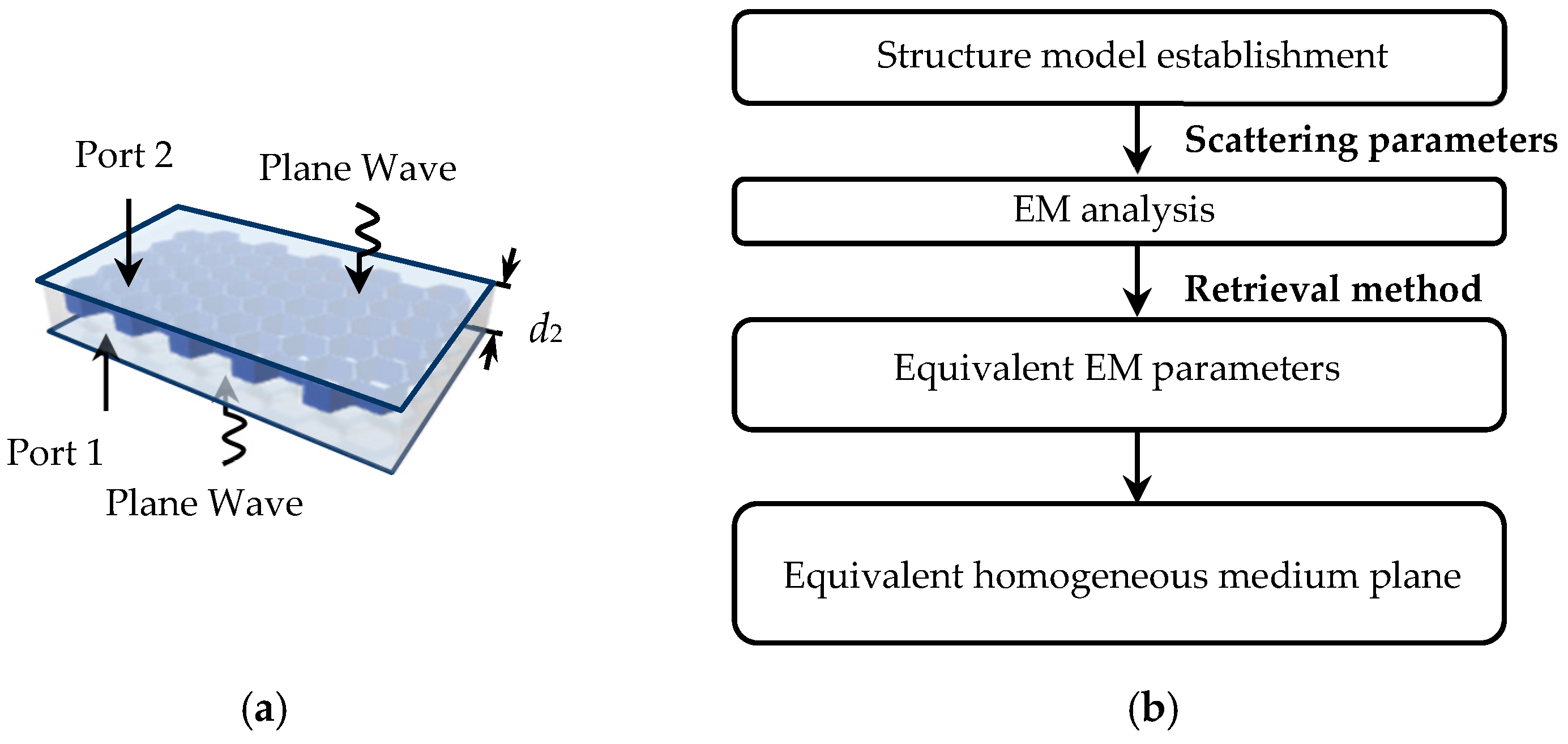
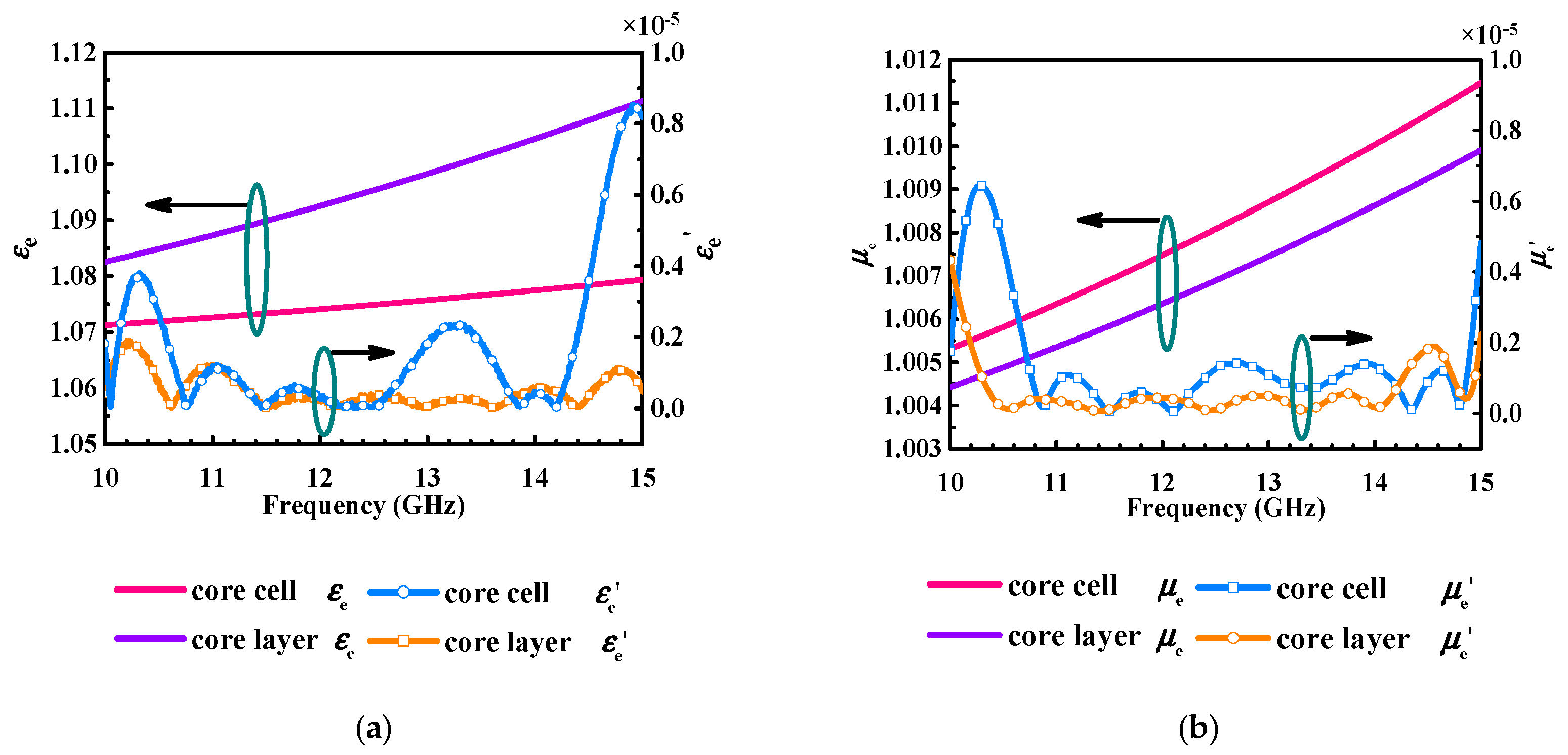
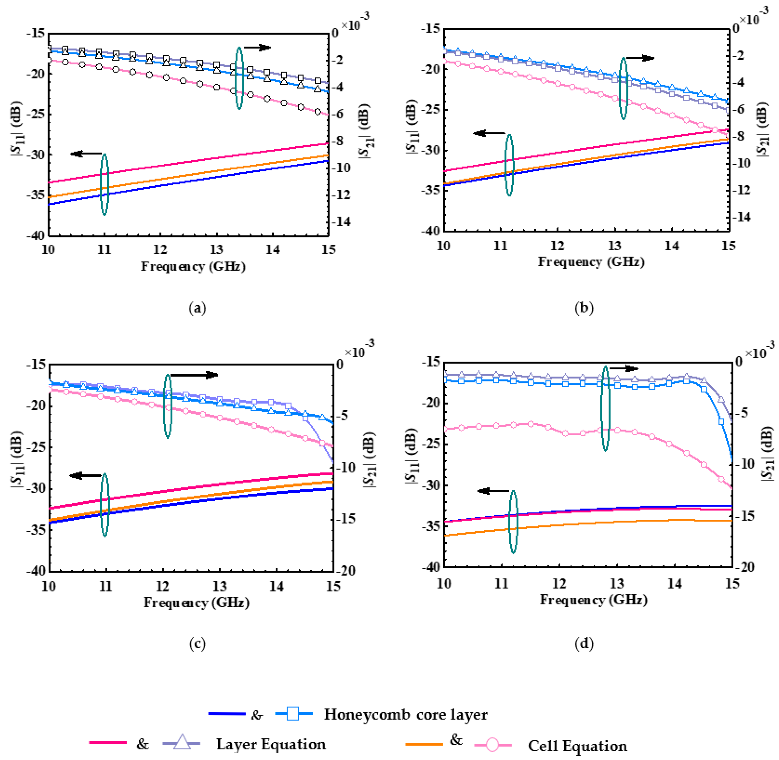
3.1. The Equivalent Medium Model of the Honeycomb Core Layer
3.2. Principle for Wideband Operation
4. Analysis of Simulation and Measurement Results
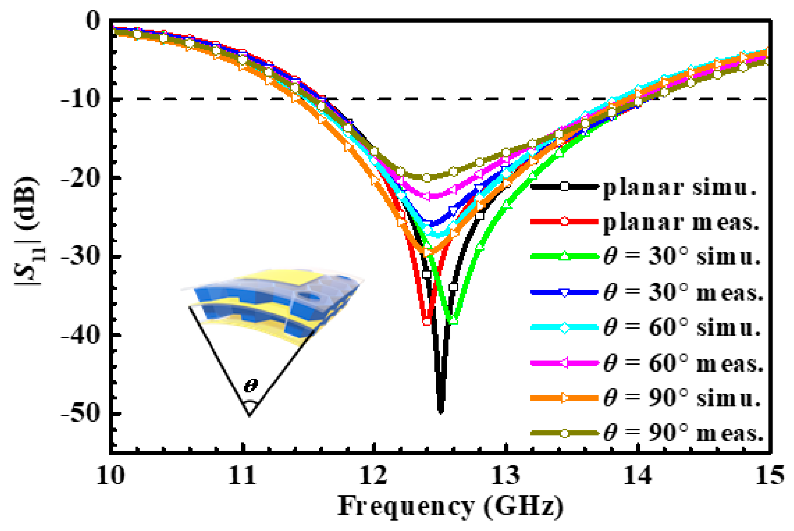
4.1. Antenna Element
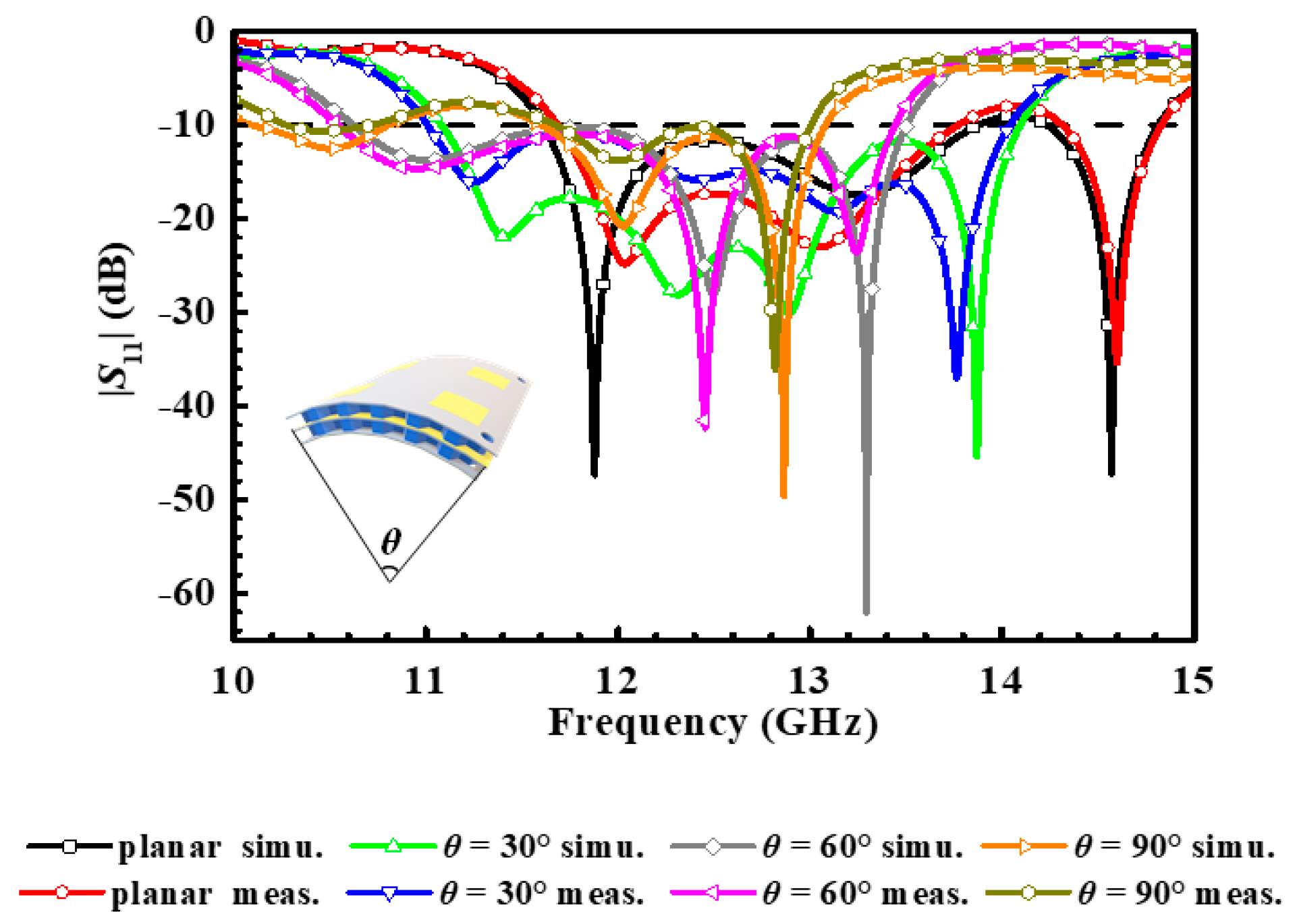
4.2. Antenna Array
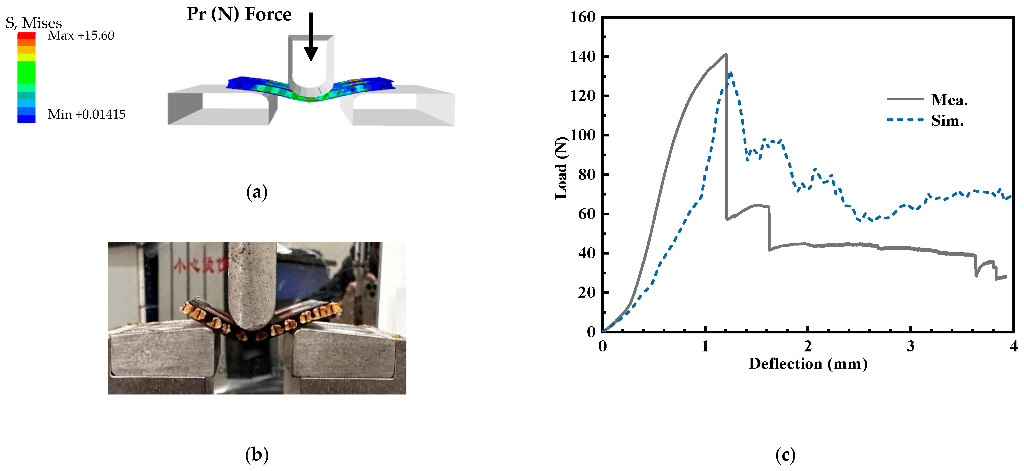
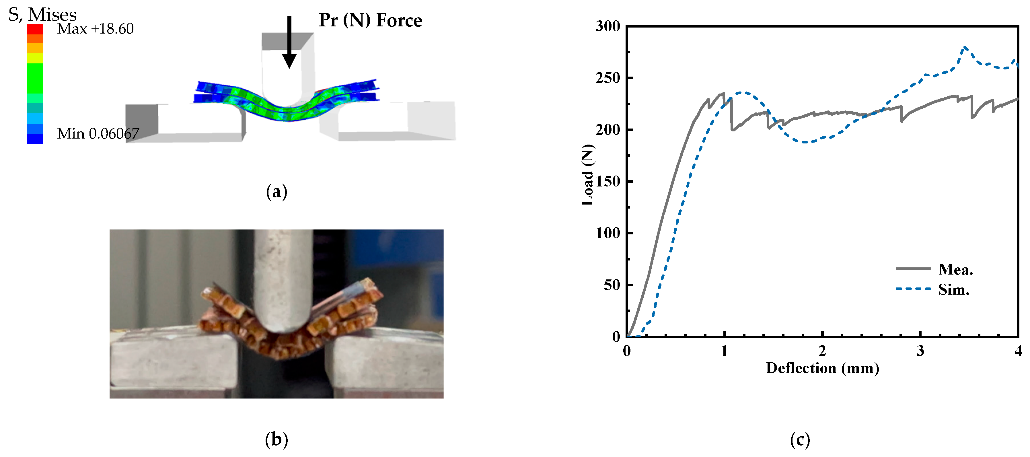
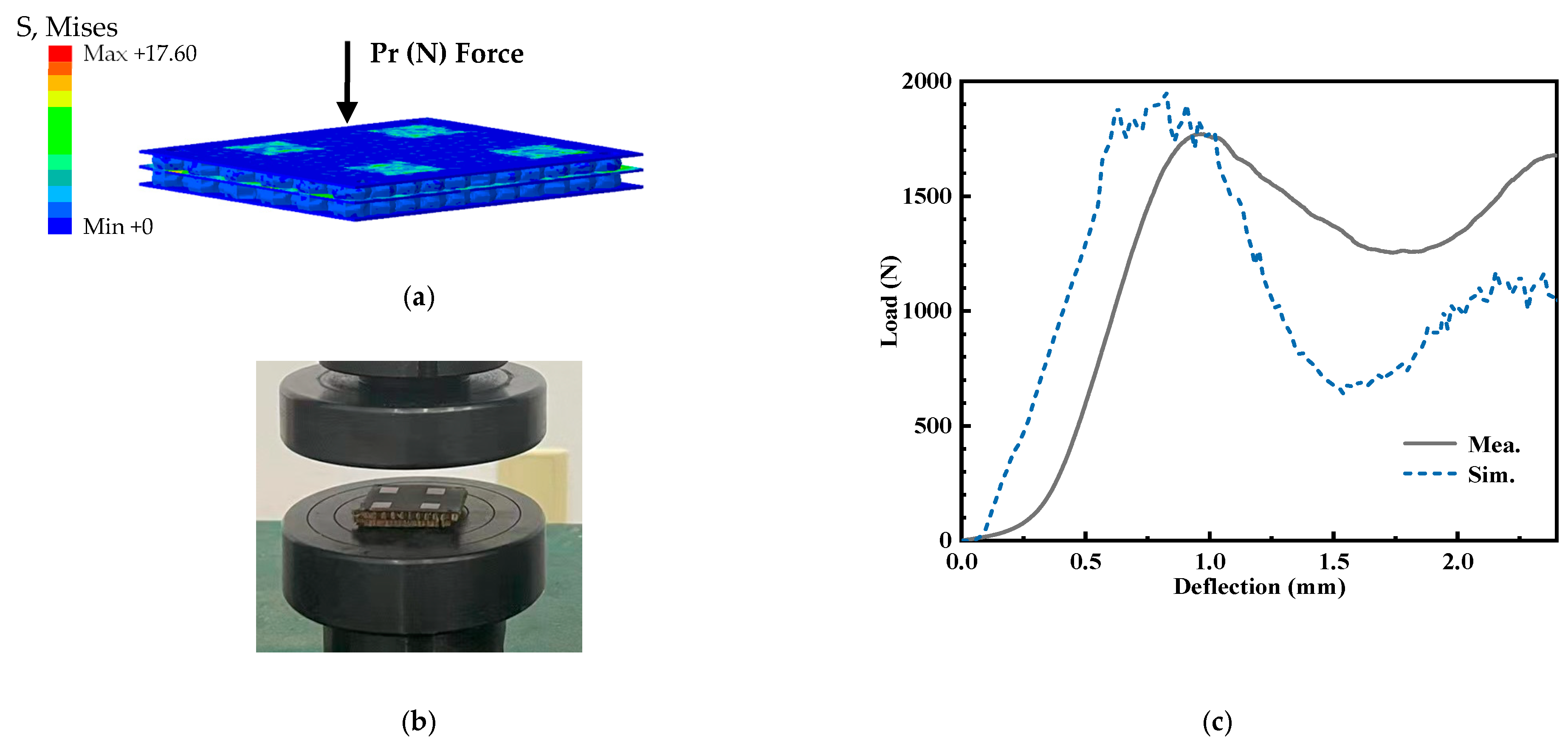
4.3. Mechanical Properties
5. Conclusions
Author Contributions
Funding
Institutional Review Board Statement
Informed Consent Statement
Data Availability Statement
Conflicts of Interest
References
- Lockyer, A.J.; Alt, K.H.; Kudva, J.N.; Kinslow, R.W.; Goetz, A.C. Conformal load-bearing antenna structures (CLAS): Initiative for multiple military and commercial applications. In Smart Structures and Materials 1997: Smart Electronics and MEMS; SPIE: Bellingham, WA, USA, 1997; Volume 3046. [Google Scholar]
- Chauhan, B.; Bhatia, M.; Chakraborty, A.; Sharma, P.S.; Sharma, A. Cylindrical conformal antenna arrays theory for military aircraft antenna. In Proceedings of the 2020 IEEE International Conference on Computing, Power and Communication Technologies (GUCON), Greater Noida, India, 2–4 October 2020; pp. 77–82. [Google Scholar]
- Song, L.; Lu, S.; Han, C.; Zhou, J.; Huang, J.; Li, P.; Ghorbani, K. Efficient computation of real-time distorted conformal load-bearing antenna structure under dynamic mechanical load based on modal superposition. IEEE J. Multiscal. Multiphys. Comput. Techniq. 2018, 3, 246–254. [Google Scholar] [CrossRef]
- Baum, T.C.; Ziolkowski, R.W.; Ghorbani, K.; Nicholson, K.J. Investigations of a load-bearing composite electrically small egyptian Axe dipole antenna. IEEE Trans. Antennas Propag. 2017, 65, 3827–3837. [Google Scholar] [CrossRef]
- Kim, C.K.; Lee, L.M.; Park, H.C.; Hwang, W.; Park, W.S. Impact damage and antenna performance of conformal load-bearing antenna structures. Smart Mater. Struct. 2003, 12, 672–679. [Google Scholar] [CrossRef]
- Baek, S.M.; Ko, M.G.; Kim, M.S.; Joo, Y.S. Structural design of conformal load-bearing array antenna structure (CLAAS). Adv. Compos. Mater. 2017, 26, 29–42. [Google Scholar] [CrossRef]
- Bishop, N.A.; Miller, J.; Zeppettella, D.; Baron, W.; Tuss, J.; Ali, M. A Broadband High-Gain Bi-Layer LPDA for UHF Conformal Load-Bearing Antenna Structures (CLASs) Applications. IEEE Trans. Antennas Propag. 2015, 65, 2359–2364. [Google Scholar] [CrossRef]
- Kirtania, S.G.; Elger, A.W.; Hasan, M.R.; Wisniewska, A.; Sekhar, K.; Karacolak, T.; Sekhar, P.K. Flexible antennas: A review. Micromachines 2020, 11, 847. [Google Scholar]
- Healey, R.; Nicholson, K.J.; Wang, J.; Patniotis, J.E.; Lynch, T.; Chiu, W.K. Conformal Load-Bearing Antenna Structures—Mechanical Loading Considerations. Sensors 2022, 22, 48. [Google Scholar] [CrossRef]
- Wang, Z.; Zhang, L.; Bayram, Y.; Volakis, J.L. Embroidered e-fiber-polymer composites for conformal and load bearing antennas. In Proceedings of the 2010 IEEE Antennas and Propagation Society International Symposium, Toronto, ON, Canada, 11–17 July 2010; pp. 1–4. [Google Scholar]
- Mohamadzade, B.; Simorangkir, R.B.V.B.; Maric, S.; Lalbakhsh, A.; Esselle, K.P.; Hashmi, R. Recent developments and state of the art in flexible and conformal reconfigurable antennas. Electronics 2020, 9, 1375. [Google Scholar]
- Bhowmik, L.M.; Armiento, C.; Akyurtlu, A.; Miniscalco, W.; Chirravuri, J.; McCarroll, C. Design and analysis of conformal ku-band microstrip patch antenna arrays. In Proceedings of the 2013 IEEE International Symposium on Phased Array Systems and Technology, Boston, MA, USA, 15–18 October 2013; pp. 815–820. [Google Scholar]
- Park, J.; Park, S.; Yang, W.; Kam, D.G. Folded aperture coupled patch antenna fabricated on FPC with vertically polarised end-fire radiation for fifth-generation millimetre-wave massive MIMO systems. IET Micro. Antennas Propag. 2019, 13, 1660–1663. [Google Scholar]
- Bhatnagar, G.D.; Saini, J.S.; Saxena, V.K.; Joshi, L.M. Design of broadband circular patch microstrip antenna with diamond shape slot. Indian J. Radio Space Phys. 2011, 40, 275–281. [Google Scholar]
- Sun, W.; Li, Y.; Zhang, Z.; Feng, Z. Broadband and low-profile microstrip antenna using strip-slot hybrid structure. IEEE Antennas Wirel. Propag. Lett. 2017, 16, 3118–3121. [Google Scholar]
- Cheng, B.; Du, Z.; Huang, D. A differentially fed broadband multimode microstrip antenna. IEEE Antennas Wirel. Propag. Lett. 2020, 19, 771–778. [Google Scholar] [CrossRef]
- Liu, N.-W.; Zhu, L.; Choi, W.-W.; Zhang, X. A Low-profile aperture-coupled microstrip antenna with enhanced bandwidth under dual resonance. IEEE Trans. Antennas Propag. 2017, 65, 1055–1062. [Google Scholar]
- Zheng, L.; Cao, J.; Chen, S.-Q.; Jiang, Z.-N. Study on bandwidth and mode characteristics for microstrip antenna. J. Microw. 2016, 32, 45–48. [Google Scholar]
- Yuan, X.-W.; Yang, Z.; Gou, M.-J.; Yang, M.-L.; Sheng, X.-Q. A flexible and efficient method for the analysis of electromagnetic scattering by inhomogeneous objects with honeycomb structures. IEEE Antennas Wirel. Propag. Lett. 2022, 21, 541–545. [Google Scholar] [CrossRef]
- Peshlov, V.; Alexandrov, S.; Dankov, P. Numerical simulation of multilayer radome with anisotropic materials. In Proceedings of the 15th International Conference on Microwaves, Radar and Wireless Communications, Warsaw, Poland, 17–19 May 2004; pp. 563–566. [Google Scholar]
- Zhou, L.; Pei, Y.; Fang, D. Dual-band a-sandwich radome design for airborne applications. IEEE Antennas Wirel. Propag. Lett. 2016, 15, 218–221. [Google Scholar] [CrossRef]
- Nicolson, A.M.; Ross, G.F. Measurement of the intrinsic properties of materials by time-domain techniques. IEEE Trans. Instrum. Meas. 1970, 19, 377–382. [Google Scholar]
- Zhao, Y.-C.; Liu, J.-F.; Song, Z.-G.; Xi, X.-L. Novel closed-form expressions for effective electromagnetic parameters of honeycomb radar-absorbing structure. IEEE Trans. Antennas Propag. 2016, 64, 1768–1778. [Google Scholar] [CrossRef]
- Castro, A.T.; Sharma, S.K. Inkjet-printed wideband circularly polarized microstrip patch array antenna on a PET film flexible substrate material. IEEE Antennas Wirel. Propag. Lett. 2018, 17, 176–179. [Google Scholar] [CrossRef]
- Boyuan, M.; Pan, J.; Wang, E.; Luo, Y. Conformal bent dielectric resonator antennas with curving ground plane. IEEE Trans. Antennas Propag. 2019, 67, 1931–1936. [Google Scholar] [CrossRef]
- Wang, C.; Li, P.; Ren, Z.; Meng, F. Effect and experiment of curvature radius of 3-D printed conformal load-bearing antenna array on EM performance. Int. J. RF Microw. Comput. Aided Eng. 2020, 30, e22130. [Google Scholar]
- Kulkarni, J.; Jayshri, A.G.; Elfergani, I.; Anguera, J.; Zebiri, C. Dual polarized, multiband four-port decagon shaped flexible MIMO antenna for next generation wireless applications. IEEE Access 2022, 10, 128132–128150. [Google Scholar] [CrossRef]
- Du, C.Z.; Wang, X.; Jin, G.Y. A compact tri-band flexible MIMO antenna based on liquid crystal polymer for wearable applications. Prog. Electromagn. Res. M 2021, 102, 217–232. [Google Scholar]
- Lee, H.; Park, Y.B. Wideband ring-monopole flexible antenna with stub for WLAN/C-Band/X-Band applications. Appl. Sci. 2022, 12, 10717. [Google Scholar] [CrossRef]
- Kulkarni, N.P.; Bahadure, N.B.; Patil, P.; Kulkarni, J.S. Flexible interconnected 4-port MIMO antenna for sub-6 GHz 5G and X band applications. AEU-Int. J. Electron. Commun. 2022, 152, 154243. [Google Scholar] [CrossRef]


| W1 | W2 | W3 | W4 | W5 | L1 | L2 | L3 |
|---|---|---|---|---|---|---|---|
| 14.52 | 7.04 | 0.51 | 0.64 | 32.84 | 14.52 | 6.9 | 6.51 |
| L4 | L5 | C1 | h1 | h2 | ε1 | ε2 | d1 |
| 8.4 | 36.65 | 1.83 | 0.3 | 2 | 3.5 | 4 | 18.32 |
| State | BW | Peak Gain (dBi) | 3 dB Beam Angle (°) |
|---|---|---|---|
| Planar | 20.68% | 8.32 | 67.0 |
| 30° | 24.16% | 8.25 | 67.4 |
| 60° | 23.82% | 8.12 | 67.8 |
| 90° | 23.12% | 8.03 | 68.5 |
| State | BW | Peak Gain (dBi) | 3 dB Beam Angle (°) |
|---|---|---|---|
| Planar | 20.68% | 14.7 | 38.6 |
| 30° | 24.16% | 14.4 | 37.8 |
| 60° | 23.82% | 12.9 | 38.7 |
| 90° | 23.12% | 12.7 | 39.1 |
| Antenna | Size (mm3) | Frequency (GHz) | Methods | BW | SLL (dB) | Flexible | With CLAS |
|---|---|---|---|---|---|---|---|
| Ref. [24] | 46.36 × 46.36 × 1.78 (4 elements) | 7.7–8.3 | Inkjet printing | 12.5% | −14 | Yes | Yes |
| Ref. [25] | 33 × 20 × 5 (1 element) | 6.8–8.3 | DRA | 18.4% | −10 | No | No |
| Ref. [26] | 44 × 85 × 4.9 (4 elements) | 12.2–13.4 | 3D printing | 11.6% | −8 | Yes | No |
| Ref. [27] | 45 ×38 × 0.2 (4 elements) | 2.37–2.61 | Fractal structure | 9.63% | - | Yes | No |
| 3.30–4.41 | 28.79% | ||||||
| 4.98–5.90 | 16.91% | ||||||
| Ref. [28] | 59 × 29 × 0.1 (2 elements) | 2.38–2.55 | Inverted-F branch | 7.2% | - | Yes | No |
| 3.37–3.60 | 6.4% | ||||||
| 4.92–5.37 | 9.3% | ||||||
| Ref. [29] | 32 × 40 × 4.9 (4 elements) | 2.36–2.87 | Fractal structure and multi-branch | 15.68% | - | Yes | No |
| 3.4–12 | 111.69% | ||||||
| Ref. [30] | 55 × 55 × 0.2 (1 element) | 3.34–5.01 | Multi-branch | 40% | - | Yes | No |
| 8.9–9.2 | 3.31% | ||||||
| This work | 32.84 × 36.65 × 4.9 (4 elements) | 11.67–13.76 and 14.33–14.83 (planar state) | Aperture-coupled feeding | 20.68% | −24 | Yes | Yes |
| 11.08–14.1 (30° bending) | 24.16% | ||||||
| 10.63–13.5 (60° bending) | 23.82% | ||||||
| 1.55–14.33 (90° bending) | 23.12% |
Disclaimer/Publisher’s Note: The statements, opinions and data contained in all publications are solely those of the individual author(s) and contributor(s) and not of MDPI and/or the editor(s). MDPI and/or the editor(s) disclaim responsibility for any injury to people or property resulting from any ideas, methods, instructions or products referred to in the content. |
© 2023 by the authors. Licensee MDPI, Basel, Switzerland. This article is an open access article distributed under the terms and conditions of the Creative Commons Attribution (CC BY) license (https://creativecommons.org/licenses/by/4.0/).
Share and Cite
Tang, C.; Zheng, H.; Li, Z.; Zhang, K.; Wang, M.; Fan, C.; Li, E. Broadband Flexible Microstrip Antenna Array with Conformal Load-Bearing Structure. Micromachines 2023, 14, 403. https://doi.org/10.3390/mi14020403
Tang C, Zheng H, Li Z, Zhang K, Wang M, Fan C, Li E. Broadband Flexible Microstrip Antenna Array with Conformal Load-Bearing Structure. Micromachines. 2023; 14(2):403. https://doi.org/10.3390/mi14020403
Chicago/Turabian StyleTang, Can, Hongxing Zheng, Ziwei Li, Kanglong Zhang, Mengjun Wang, Chao Fan, and Erping Li. 2023. "Broadband Flexible Microstrip Antenna Array with Conformal Load-Bearing Structure" Micromachines 14, no. 2: 403. https://doi.org/10.3390/mi14020403