Article

A New Inner Fabrication Method of Internal Cavity in Metal under Compound Acoustic Fields

School of Mechanical Engineering, Hangzhou Dianzi University, Hangzhou 310018, China
*
Author to whom correspondence should be addressed.
Micromachines 2023, 14(4), 719; https://doi.org/10.3390/mi14040719
Submission received: 16 February 2023 / Revised: 15 March 2023 / Accepted: 22 March 2023 / Published: 24 March 2023
(This article belongs to the Section E:Engineering and Technology)

Abstract

:
In order to realize direct manufacturing of cavity inside metal without assembly, this paper investigates the mechanism of cavity manufacturing inside metals under compound acoustic fields. First, a local acoustic cavitations model is established to study the single bubble generation at fixed point in Ga-In metal droplets, which has a low melting point. Second, cavitation-levitation acoustic composite fields are integrated with the experimental system for simulation and experimentation. Through COMSOL simulation and experimentation, this paper expounds the manufacturing mechanism of metal internal cavity under acoustic composite fields. The key problem is to control the duration of the cavitation bubble by controlling the driving acoustic pressure’s frequency and the magnitude of ambient acoustic pressure. Under the condition of composite acoustic fields, this method realizes the direct fabrication of cavity inside Ga-In alloy for the first time.

1. Introduction

In 2004, Professor Hanmin Shi proposed ‘the internal processing method [1]’, which brings the processing energy to the interior of the material, targeting specific positions to fabricate desired structures or physical and chemical properties. Currently, internal processing technology is widely studied. Among these studies, femtosecond laser processing has achieved significant research results and application value in the internal processing of transparent materials, such as silicon and polymer [2,3,4,5]. Compared to traditional processing methods, the development of internal processing technology is expected to solve the problems of complex processing technology, high energy consumption, and difficulty in manufacturing complex microstructures. However, the flaw of laser internal processing technology is also evident, which is the inability to process the interior of non-transparent materials, such as non-ferrous metals. Based on this, this paper proposes the application of ultrasonic energy to the interior of metal to realize direct processing inside of metal, which is expected to solve the technical problem that femtosecond laser processing cannot process the interior of metal.
To achieve ultrasonic internal machining, two challenges need to be addressed: controlling the position and the size of cavitation bubbles. In 1949, Rayleigh proposed the bubble dynamics equation for analyzing the cavitation flow in a fluid field with a relatively small number of cavitation bubbles [6]. Subsequently, Noltingk, Neppiras, and Poritsky modified Rayleigh’s equation to account for the dynamics of bubbles in a viscous fluid [7]. This signifies the establishment of the classical equation that describes the dynamic behavior of bubbles in fluid. Based on the solution and correction of this equation, researchers have conducted a lot of research on ultrasonic cavitation behavior. In 2002, Yutaka Abe et al. studied the precise control of bubble position in a standing wave field. Through experiments, it was confirmed that ultrasonic standing waves can accurately control the position of bubbles in the liquid [8]. In 2015, Sheng Zhuang-Zhi studied the position of ultrasonic cavitation bubble in liquid and the direction of motion under the action of the primary Bjerknes force [9]. In 2018, Zang et al. utilized acoustic levitation to open and close the shell of liquid particles and proposed a new technology for generating cavitation bubbles from droplets. When the cavity volume reached a critical point, the acoustic resonance induced buckling instability, leading to a sharp increase in the volume of the cavitation bubble induced by the acoustic standing wave field. This resulted in the dramatic expansion of the cavity and its rapid closure, forming the cavitation bubble [10,11,12,13,14,15,16,17,18]. The buckling instability of the liquid film under acoustic levitation provides a method for converting droplets into large cavitation bubbles. In 2020, Chen Shu et al. studied the characteristics of thin metal liquid cavitation bubbles, but the number, size, and location of cavitation bubbles were uncontrollable [19,20]. Research on cavitation bubbles in liquid metal materials mainly focuses on the occurrence of a group of bubbles in solder [21,22,23,24]. Recently, research on ultrasonic cavitation has mainly focused on ultrasonic cleaning, cavitation degradation, and medical treatment. However, a cavity processing method with a controllable geometric size has not been found in metal. Ultrasonic cavitation can be divided into two states: transient cavitation and stable cavitation. Even in the stable cavitation state, the position and size of cavitation are difficult to control. This paper is based on the cavitation bubble dynamics equation [7] and standing wave position control principle [8,9]. The cavity processing method of a single cavitation bubble in low melting point alloy under the action of a composite field is studied with the aim of realizing the direct processing of a spherical cavity inside a metal droplet.

2. Models and Methods

The models used for acoustic cavitation and acoustic levitation vary slightly depending on their respective application fields. Typically, uniaxial acoustic field models are used, and research on acoustic cavitation and acoustic levitation is conducted separately. This paper proposes an innovative approach that combines a uniaxial standing acoustic wave field with an ultrasonic needle point acoustic field. During the experiment, these two acoustic fields are relatively independent yet coupled with each other. The standing acoustic wave field provides varying environmental acoustic pressure and acoustic radiation force, while the cavitation acoustic field provides cavitation acoustic pressure.

2.1. Single Acoustic Cavitations’ Model in Droplet

A three-dimensional coordinate system is used to establish the ultrasonic tip-monopole model, as depicted in Figure 1. The objective is to establish a theoretical research model for monopole ultrasonic cavitation.
The coordinate plane used in this model is the XOY plane with the center of the circular piezoelectric transducer as the origin. One end of the ultrasonic needle is attached to the transducer, with its vibration direction along the Z-axis direction. The local acoustic pressure model at the needle tip follows monopole vibration.
P t i p = P g e i k z ω t , P g = ρ g c g ω g u g
In this equation, ug is the vibration amplitude of the needle tip, which is a constant; ωg is the angular frequency of the tip’s vibration; and cg is the acoustic propagation velocity in the Ga-In alloy. R0 represents the incident radius, l is the length of the needle tip, and Rg is the radius of the needle tip.
The vibration of the needle tip affects the initial cavitation, causing it to be stretched and compressed by the ultrasonic vibration. The radius of the initial cavitation under the alternating acoustic pressure is described by the R-P equation. Considering the surface tension and viscosity factors, the radius variation model is as follows:
R R ¨ + 3 2 R ˙ 2 = 1 ρ P
P represents the local acoustic pressure inside and outside the cavitation bubble, and the formula is:
P = P P v + 2 σ R R μ R 3 γ 2 σ R μ 4 μ R ˙ R μ + P v P + P t i p
In the initial condition at t = 0: R = Rμ, d R d t = 0 , where Rμ is the initial value of the bubble nucleus. In the formula, Ptip is the ultrasonic pressure at the needle tip; P’ is the environmental standing acoustic pressure; γ is the polytropic index of gas; R is the transient radius of the cavitation bubble; c is the acoustic velocity of the medium; and σ, μ, and ρ are the surface tension coefficient, viscosity coefficient, and density of the medium, respectively.

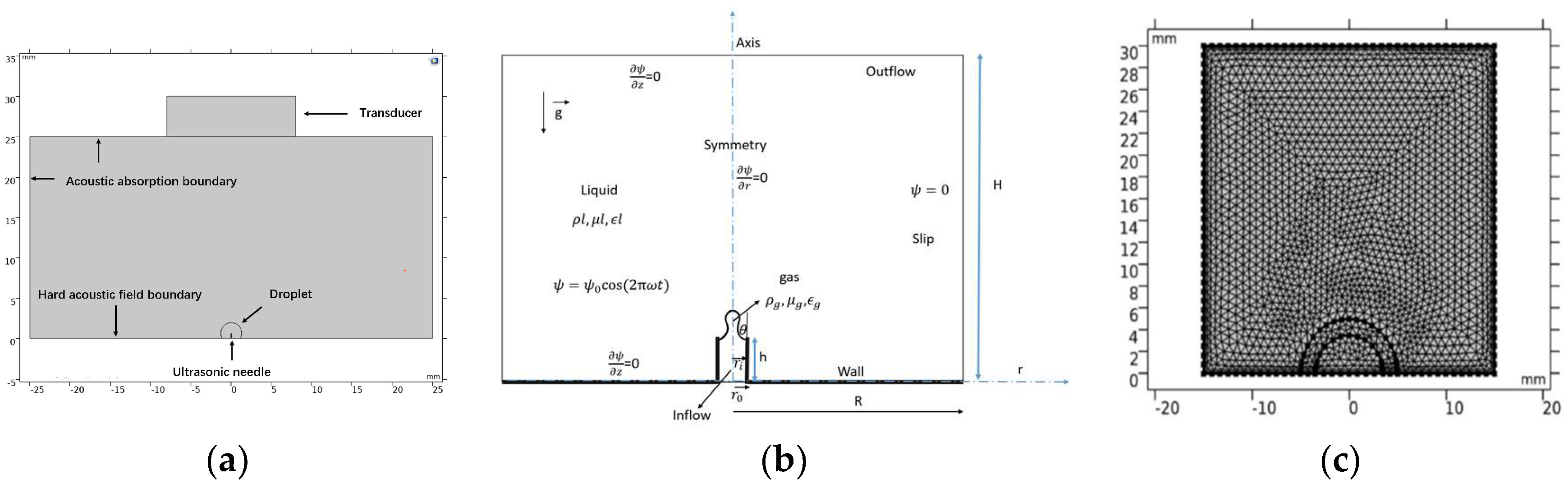
2.2. Compound Acoustic Fields Model of Cavitations and Levitation

The ultrasonic cavitation and levitation composite fields model is designed by introducing the ultrasonic cavitation-levitation theory. The reflection end is transformed into the working end with a piezoelectric ultrasonic needle tip. The droplet is placed on the surface of the reflection end and the needle tip is inside the metal droplet. Its function is to realize the standing wave levitation of the droplet in the external space and the local acoustic cavitations of the needle tip inside the droplet. The structure of the ultrasonic compound fields is shown in Figure 2. The meaning of the number in the model is provided on the right side of the picture, as shown in Figure 2.
Under the action of compound acoustic fields between 7 and 8, the environmental pressure P around the metal droplets follow the acoustic standing wave pressure law:
P = 2 P u cos k z cos ω t + P 0
where Pu is the pressure amplitude of acoustic wave field, and P0 is the atmosphere pressure. After acoustic cavitations, Acoustic radiation force and second-order differential equation is used to describe the suspending motion of metal droplets:
m p d 2 z d t 2 = F 6 π η r u r z 1 2 ρ m v p d u r z d t ρ p v p g
where urz is the relative velocity of the bubble, and mp is the mass of the droplet.
Conclusively, the acoustic cavitation-levitation behaviors will follow (1)~(5) formula.

3. COMSOL Simulation Results and Discussion

The setup for COMSOL simulation of acoustic compound fields involves the following steps:
(1)
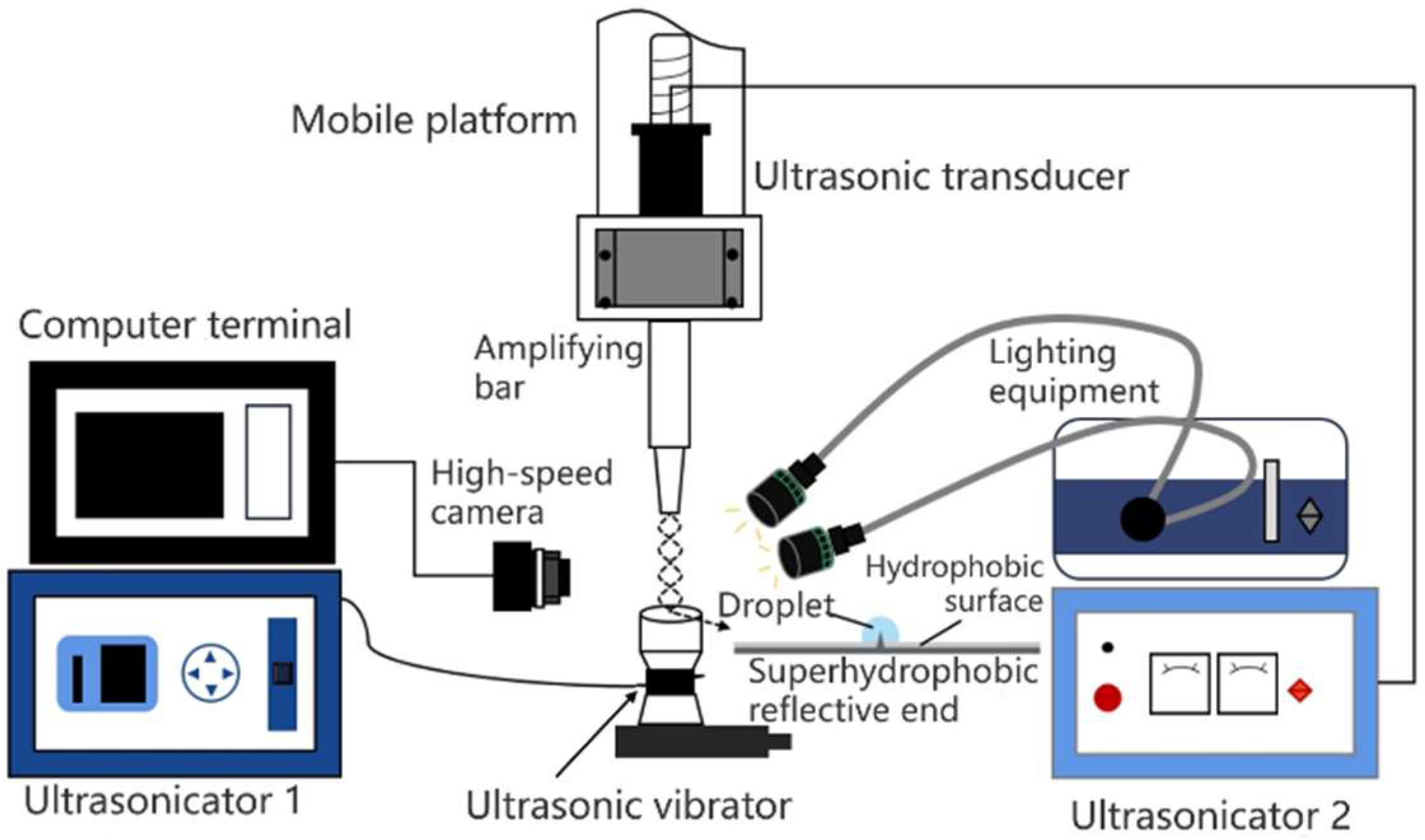
The acoustic cavitations are composed of the needle tip ultrasonic emitter 1, ultrasonic needle tip 3, and annular ceramic plate 5;
(2)
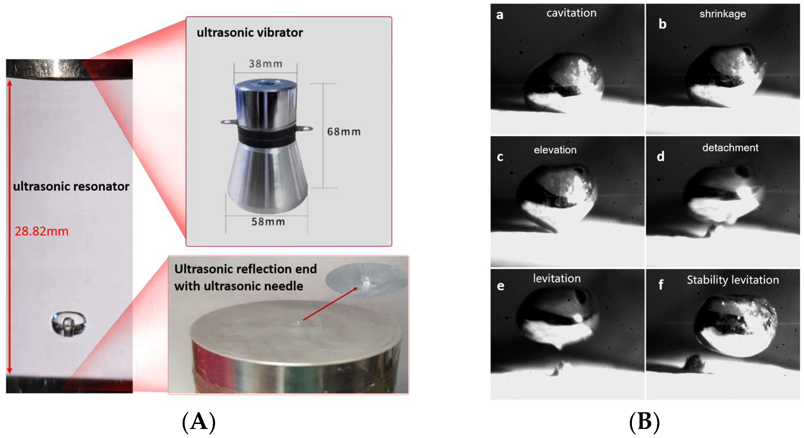
The acoustic standing wave field in Z direction is formed by wave emission end 8 and reflection end 7;
(3)
The reflection end 7 is fixed with the ultrasonic needle-tip 1, and the isolation pad 4 is used in the middle;
(4)
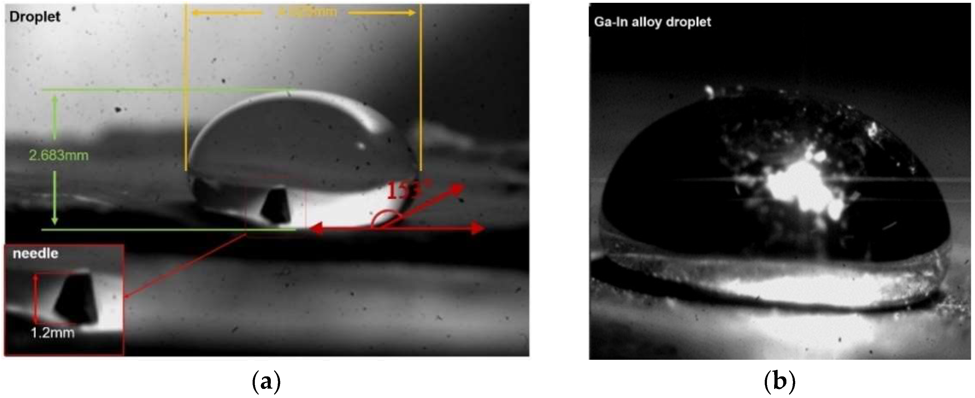
Ga-In alloy droplet 9 was placed on annular ceramic plate 5, and the middle is isolated by a hydrophobic membrane 6. The radius of the solid–liquid interface is set as rg, and the wetting angle of the solid–liquid interface was set as θ. The measured droplet volume is about 1 mL;
(5)
The pointer ultrasonic emitter 3 emits ultrasonic waves to the metal droplet 9 to form a focused acoustic field, which transforms cavitations into a cavity;
(6)
Under the coupling effect of standing wave acoustic field and acoustic flow, the liquid surface of droplet 9 shrinks, the boundary is separated, then it is stably suspended at the standing wave node;
(7)
The relationship between the length and radius of the ultrasonic needle tip in the acoustic-solid coupling fields, and the initial radius, frequency, and amplitude of the acoustic cavitation droplets were studied;
The acoustic module in COMSOL Multiphysics Software is used to visually simulate and analyze the entire computational domain, and a geometric model of the ultrasonic compound fields is established. The simulation domain is shown in Figure 3. The acoustic cavitation-levitation simulation model uses the PDE interface of the boundary partial differential equation in the form of a coefficient. For a dependent variable u:
e a 2 u t 2 + d a u t + · c u α u + ξ + β · u + a u = f
Coefficients in PDE form: ea is mass coefficient, da is damping coefficient, c is diffusion the coefficient, a is absorption coefficient, ξ is conservative flux source term, β is convection coefficient, and f is the source term corresponding to Formulas (2) and (3). Let ea, da, and a be equal to 0:
f = R R .. + 3 2 R 2 1 ρ p
In the CMOSOL pressure acoustic (transient state) physical field, the inner normal displacement of the transducer boundary is used to simulate the vibration of the transducer. The possible motion area around the droplet is divided into dynamic grids and the boundary probe is added to the liquid surface to calculate the surface acoustic pressure and acoustic radiation force.
In the “Two-Phase Flow, Level set (The “Two-Phase Flow” module in COMSOL Multiphysics software provides various models and methods for simulating the interaction between two or more different fluids. This includes physical phenomena, such as bubble or droplet motion, surface tension, capillary forces, and liquid turbulence in gas–liquid two-phase flow. The level set method is a mathematical approach used to describe object boundary evolution and deformation and can be applied to simulate free surface problems and interfaces between liquids and gases. In two-phase flow problems, the level set method is commonly used to track the interface between different phases. physical field, the volume force is added to the liquid phase to simulate the movement of droplets under the action of acoustic radiation force, and the displacement generated is fed back to the moving grid.
The air, Ga-In alloy, ultrasonic transducer, compound fields, piezoelectric ring, and other simulation parameters are shown in Table 1 below.

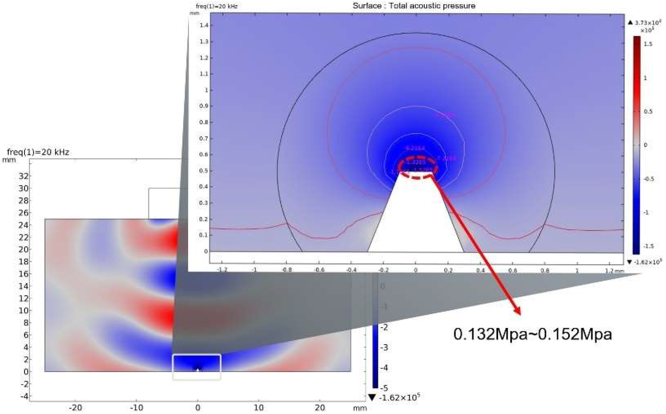
3.1. Local Acoustic Cavitations at the Tip Point inside Droplet

Selection of parameters: The frequency of the ultrasonic power supply is f = 30 kHz, the power is 500 W, the radius of the large end of the transducer is D1 = 58 mm, the working frequency of the piezoelectric ring PZT-8 is ωg = 15~70 kHz, and the power is 50 W. The weight of Ga-In alloy is 0.164 g, the density is 6.28 × 10³ kg/m3, the long axis is 2a = 4.025 mm, the short axis is 2b = 2.683 mm, the aspect ratio is 1.5, and the alloy has hydrophobic contact with the reflection end. The length of ultrasonic needle is l = 1.2 mm, tip vibration amplitude is 3.0 μm, and the radius of needle tip is R1 = 0.15 mm. A series of air grooves with Rμ = 3~12.6 μm were inscribed in the tip, and the amplitude of ultrasonic needle was 3.0 μm. The frequency solver is selected to solve the resonant frequency of the needle, and COMSOL frequency domain analysis is selected to solve the vibration characteristics of the tip.
The condition of cavitation excitation in liquid is that the acoustics pressure should reach the cavitation threshold. Since the tip has a series of air grooves, here, if the initial radius is 12.6 μm, the theoretical threshold of acoustic cavitations of Ga-In alloy is 0.12 MPa. COMSOL simulation can intuitively show the distribution of internal ultrasonic cavitation acoustic pressure. The acoustic pressure is 0.132~0.152 MPa by adding a probe to the tip. This value exceeds the cavitation threshold and can stimulate cavitation to produce a cavity. As shown in Figure 4, under the action of piezoelectric ultrasonic needle into Ga-In alloy droplets, the local acoustic field distribution is formed inside the droplets.

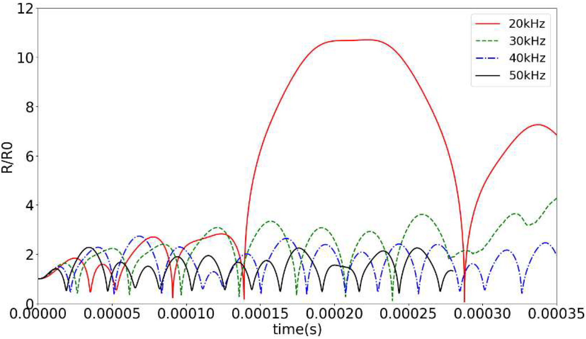
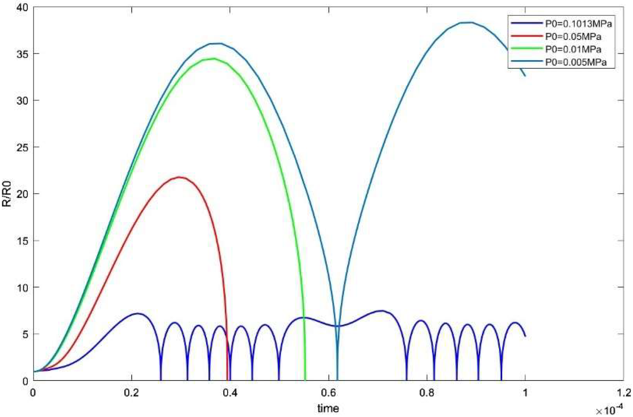
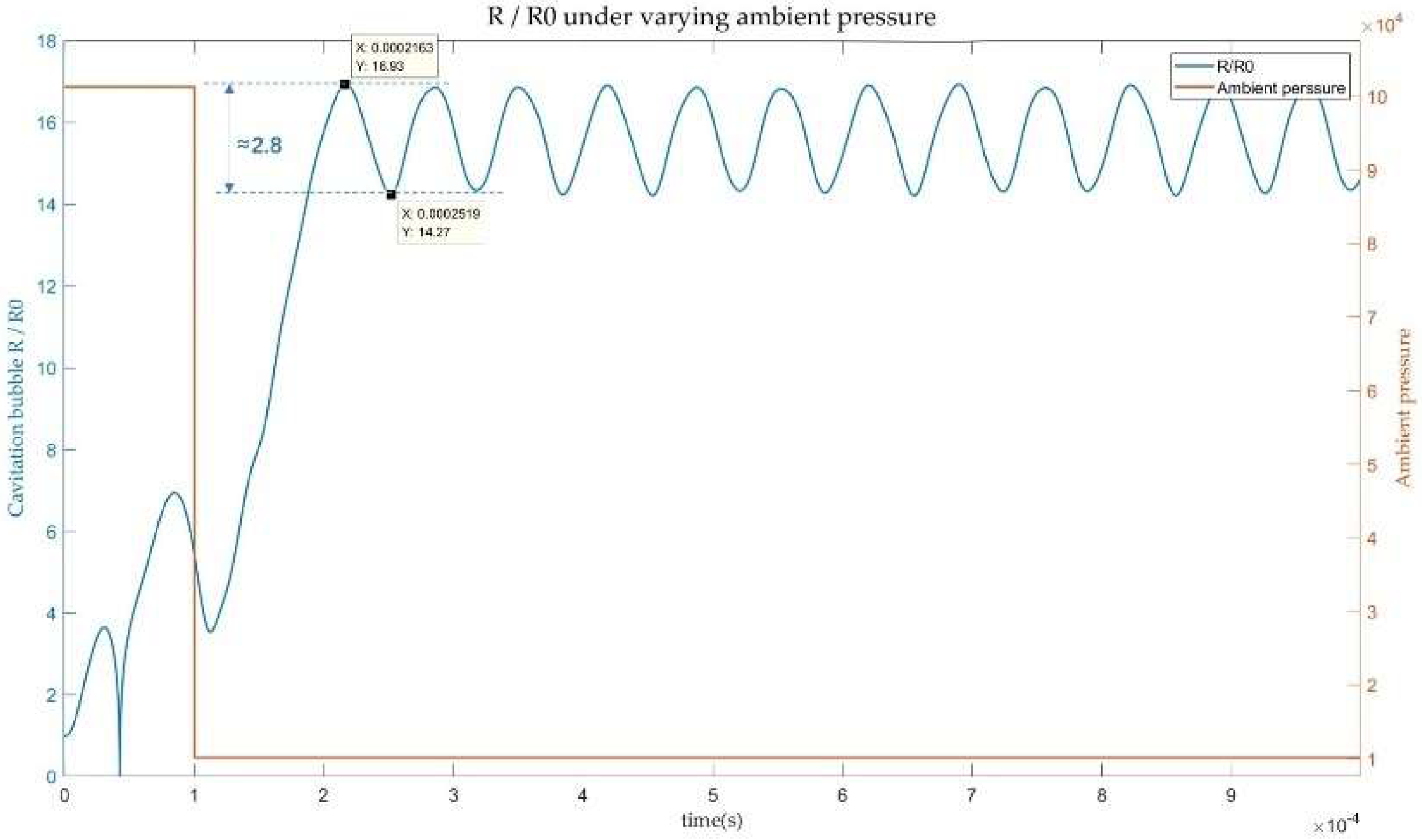
3.2. Scale Controllability of Acoustic Cavitations’ Bubble

This study focuses on the influence of driving frequency and external acoustic pressure on cavitation intensity in previous work. Taking the initial radius of Ga-In alloy as 12.6 μm and the frequencies of 20 kHz, the dynamic behavior Rmax/R0 of cavitations’ bubble at different frequencies of 20 kHz, 30 kHz, 40 kHz, and 50 kHz is shown in Figure 5 below. At the driving frequency of 20 kHz, the cavitations’ bubble can expand to 11 times or more and remain stable for enough time.
According to the analysis of Formulas (2) and (3) in the ultrasonic composite fields, a change in ambient pressure is more conducive to the generation of cavitation bubbles. MATLAB simulation was conducted with constant parameters and ambient pressure was reduced to 0.05 MPa, 0.01 MPa, and 0.005 MPa, respectively. The results showed that the duration and size of the cavitation bubbles were enhanced as the ambient pressure was reduced. Figure 6 illustrates this.
The above analysis demonstrates that the extension of cavitation duration can be achieved by adjusting the driving frequency and reducing ambient sound pressure. To investigate the evolution of cavitation droplets in the presence of initial nuclei, while also varying the ambient sound pressure mid-process, we conducted simulation experiments. Figure 7 shows that altering the ambient pressure affects the growth characteristics of cavitation bubbles, enabling them to continue growing beyond their initial rate and maintain stable oscillations for an extended period. Its oscillation error is between 2.8 times R0. Coupling multiple variables can prolong the lifetime of cavitation bubbles and prevent their collapse, which is more effective than controlling variables separately.

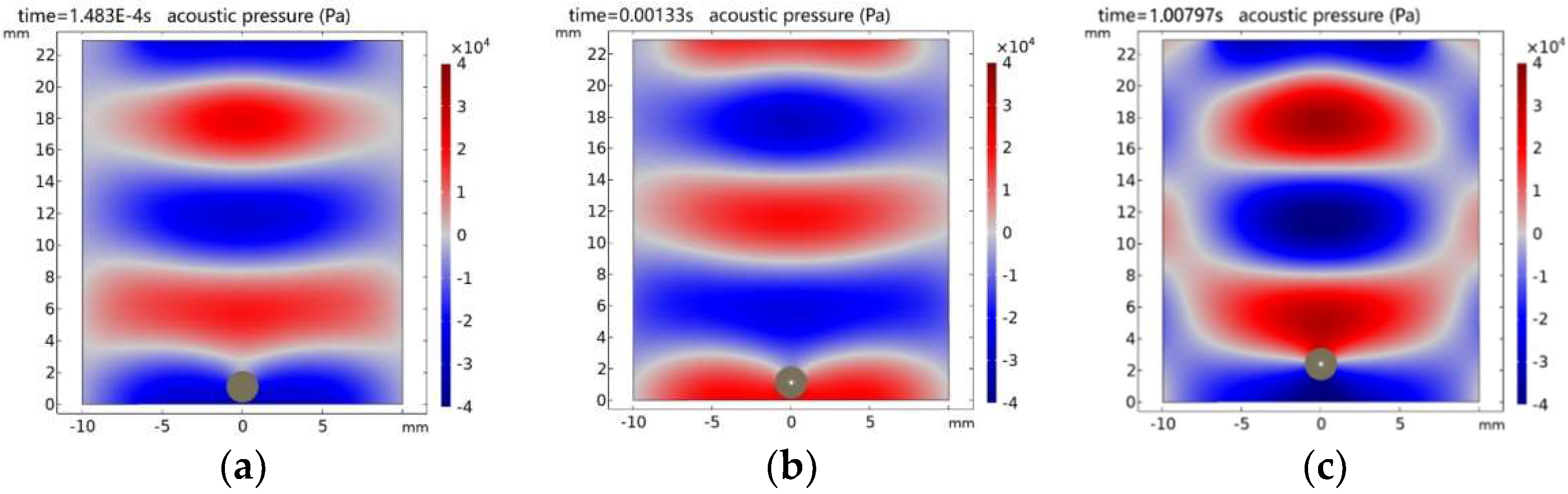
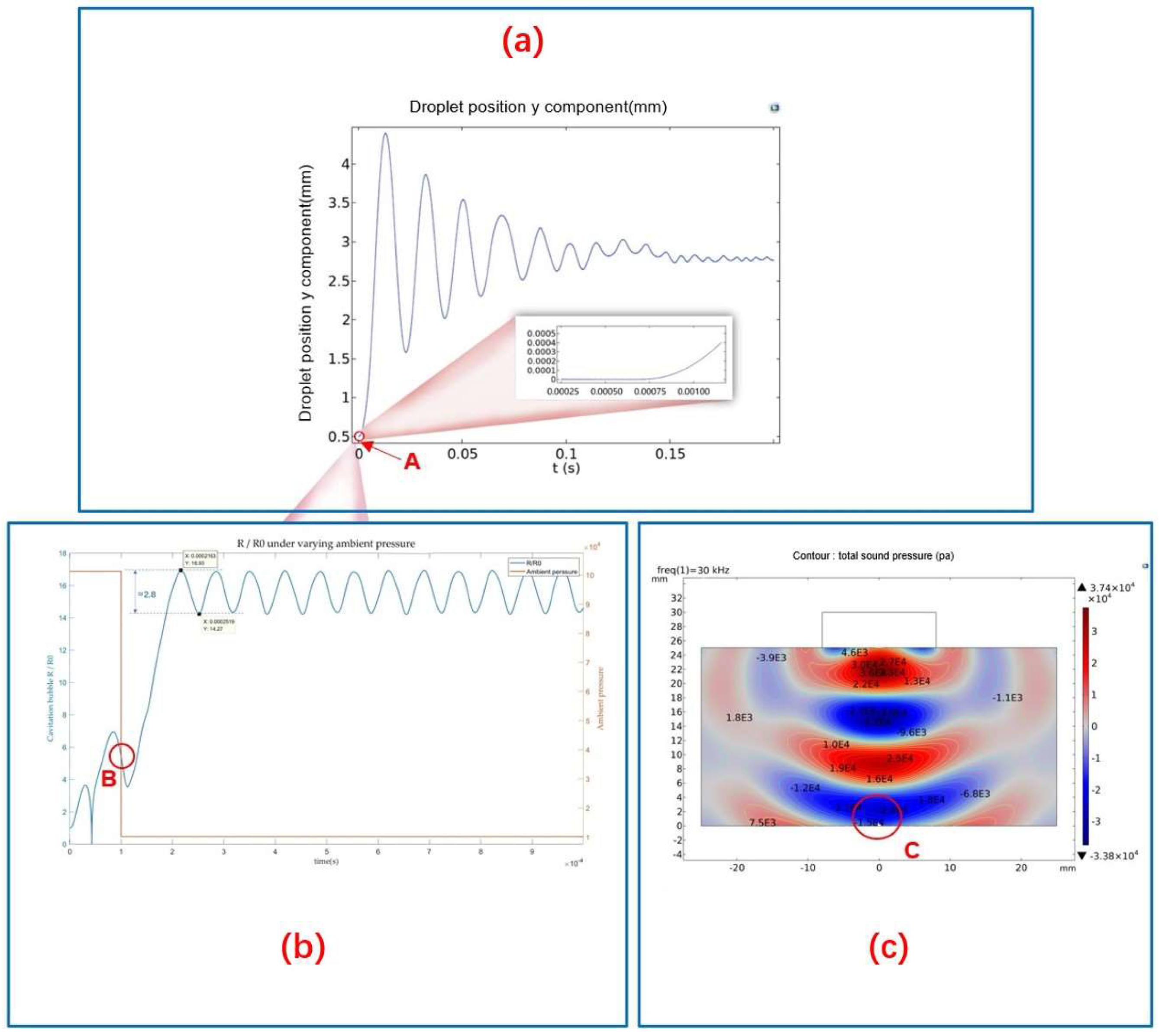
3.3. COMSOL Simulation of Acoustic Cavitation-Levitation Process

Based on COMSOL simulations, the acoustic levitation of droplets on the reflector involves three procedures: central shrinkage deformation, separation, and suspension. As shown in Figure 8, the time required for acoustic shrinkage deformation and separation is in the order of milliseconds, while the time required for acoustic levitation is in the order of seconds. However, the current cavitation method cannot guarantee the stable and safe inclusion of cavitation bubbles in the acoustic levitation process. Therefore, it is necessary to extend the method to coordinate with the acoustic levitation process.

3.4. Mechanism Analysis

Using the RP equation and the theory of controlling the position of bubbles in a standing wave field, this paper proposes a new mechanism for controlling the position and size of cavitation bubbles in compound acoustics fields. Through simulation analysis, the time axis of the entire mechanism during the cavitation levitation process is explained (as shown in Figure 9a). It can be seen from Figure 9a that the time occupied by cavitation is much shorter than the levitation time during the entire process (as shown by point A in Figure 9a). Therefore, the key to the mechanism is twofold: first, to coordinate the time for entering cavitation and levitation; second, to ensure the stable size of the cavitation bubble before entering levitation. Through simulation analysis, it is found that the size of the cavitation bubble can be controlled by controlling the frequency and reducing the ambient pressure (as shown in Figure 9b for the growth curve of acoustic cavitation bubbles under a selected frequency and reduced ambient pressure). The simulation results show that compared with stable ambient pressure, the combination of different frequencies and changing ambient pressure can realize the size control of cavitation bubbles and maintain long-term stability in a negative pressure environment with an oscillation time greater than the time required to enter levitation (as shown in Figure 9b). In this process, the compound acoustics fields constructed provide a negative pressure environment (point C in Figure 9c) and provide a microgravity environment for levitation droplet, thereby achieving controllable cavitation bubble position.

4. Test Results

Test Contents of Ga-In Alloy Inner Cavity Fabrication are as follows:
(1)
The relationship between the acoustic pressure and frequency of compound fields with the initial radius of cavitation nuclei, and the formation behaviors of acoustic cavitation bubbles are studied using Formulas (1)~(3).
(2)
Cavitations are divided into transient and steady-state cavitations. The control method for the scale of acoustic cavitation cavities should be simulated and designed. The theoretical calculations and experimental conditions for controlling the scale of cavitation and critical stable suspension without bubble explosion are studied.
(3)
In the acoustic compound fields, the radiation force is added to the metal droplet as a volume force to simulate its movement in the moving grids, and the displacement generated is fed back to the metal droplet with dynamic radius R of cavitation bubbles as the corresponding independent variable.
(4)
Pure water droplets and low melting point Ga-In alloy are used in the tests.
The test principle in the ultrasonic droplet fabrication platform with compound fields is shown in Figure 10. The main equipment and instruments include an ultrasonic power supply, transmitter 8, reflector 7 with ultrasonic needle 1, high-speed ordinary CCD, auxiliary light source, and motion control equipment. A white light source is used to illuminate the entire acoustic field, and the shooting frequency is 10,000 frames per second, with a resolution of 1024 × 512.”
Equipment manufacturers and parameters are shown in Table 2 below:

4.1. Experimental Results of Acoustic Cavitation-Levitation

The following introduces the experimental object: Since the whole experiment is a dynamic process, it is necessary to use pure water droplets as a control experiment. As shown in the following Figure 11, due to the super-hydrophobic treatment of the reflective platform, the droplets are spherical on the solid surface. The droplet is in a completely non-wetting state. The contact angle exceeds 150°, which is beneficial to the dynamic manipulation of droplets by ultrasonic composite fields.
First, taking pure water as an example, the water droplet has a density of ρ = 1.0 g/cm3, surface tension coefficient of σ = 7.60 × 10⁻² N/m3, viscosity coefficient of μ = 1.00 × 10⁻³ pa · s, and tip cavitation radius of Rμ = 12.6 μm. Under the local ultrasonic frequency of 25 kHz, cavitation bubbles were discovered at the tip of the needle and rapidly synthesized into large radius bubbles. Pure water droplets can form cavities, and the maximum radius of cavitation bubbles can increase by approximately 17 times, as shown in Figure 12A. At the same time, the ultrasonic transmitter operates at a frequency of 30 kHz, and the height H of the compound acoustic fields is 28.82 mm. The water droplets are quickly separated from the reflection end and rise to suspend at the first standing wave node. This indicates that the method of acoustic cavitation-suspension for water droplets in the compound acoustic fields is feasible under some necessary conditions, as shown in Figure 12B.
Second, taking Ga-In alloy droplets as an example, under the same conditions as shown in Figure 13A, with a cavitation core radius of 12.6 μm and a theoretical cavitation threshold of 0.12 MPa for Ga-In alloy, under the same tip amplitude as water droplets, the internal acoustic pressure of Ga-In alloy droplets is as high as 0.15 MPa, which exceeds the theoretical cavitation threshold. In the compound acoustic fields environment, its mass is 6.8 times that of water and its viscosity is roughly the same. Using a frequency of 25 kHz and an initial cavitation radius of 12.6 μm, the inner cavity radius of Ga-In alloy droplets is grown to 159 μm at the notch tip. During the suspending movement, the inner cavity remains stable without drifting in the compound acoustic fields environment. The whole cavitation-levitation process of Ga-In alloy mainly includes six stages, as shown in Figure 13B. The entire process was observed by a high-speed CCD.

4.2. Experimental Results Analysis

Under the conditions of ultrasonic composite fields, cavitation and levitation experiments were conducted on droplets with an initial bubble core size of 12.6 μm. The experimental results showed that the cavitation bubble of pure water droplets reached approximately 17 times the initial size, and the cavitation bubble radius of Ga-In alloy droplets also reached 159 μm, which was consistent with the simulation results. Additionally, after the droplet with a cavity was stably levitated in the standing wave field, the cavitation bubble remained mostly stable in the upper position of the droplet center, which was consistent with the simulated analysis position.

5. Conclusions

Through experiments and COMSOL simulation of whole dynamic processes, this paper clarifies the mechanism of fabricating internal microcavity in low melting point’s alloy, establishing a single and size controllable internal microcavity fabrication method by the acoustic cavitation and levitation processes in turn under compound acoustic fields. The main conclusions are as follows:
(1)
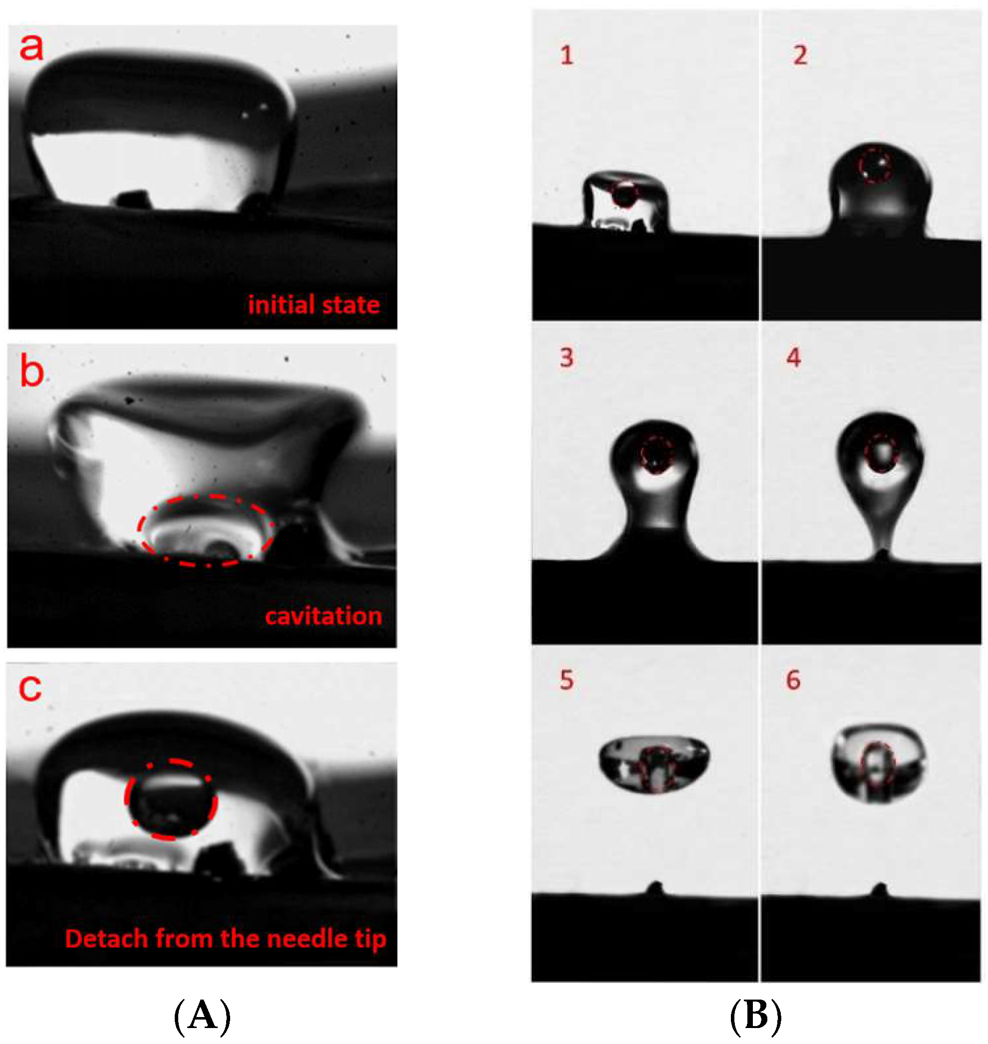
The acoustic levitation of droplets includes the processes of central contraction deformation, separation, and suspension, which typically takes milliseconds to seconds. However, the acoustic cavitation process of metal droplets only takes microseconds. This study constructs compound ultrasound fields to coordinate the cavitation-levitation process, ensuring the orderly progression of cavitation and levitation processes at specific time points to generate and maintain internal cavities.
(2)
Through simulation analysis, this study investigates the effects of ultrasonic frequency and ambient pressure on cavitation time and finds that reducing the frequency and negative pressure environment can prolong cavitation time. By selecting a parameter combination and coupling with the ultrasonic composite fields, the growth and stability of cavitation bubbles are successfully achieved.
(3)
This study establishes an ultrasonic composite fields and clarifies the manufacturing mechanism of controllable size and position of internal cavities, which is verified by simulation and experimental analysis. The mechanism demonstrates the feasibility of internal processing within metal droplets.
As the existing laser internal processing method in transparent materials, the metal material inner cavity processing method proposed in this paper has many vigorous prospects in the inner structure’s fabrication in black materials in the future.

Author Contributions

Conceptualization, L.W.; methodology, Z.Z.; software, Z.W.; validation, Y.W. (Yaxing Wang) and Z.W.; formal analysis, Y.W. (Yaxing Wang); investigation, Y.W. (Yajing Wang); resources, G.W.; writing—original draft preparation, Z.Z.; writing—review and editing, Z.Z.; supervision, L.W.; visualization, Z.W.; project administration, L.W.; funding acquisition, L.W. and H.W. All authors have read and agreed to the published version of the manuscript.

Funding

This research was supported by the National Natural Science Foundation of China (52175460, 51775154, and 11902107), Zhejiang Provincial Natural Science Foundation of China (LY21A020009).

Institutional Review Board Statement

This paper does not involve any moral and engineering ethical issues.

Informed Consent Statement

This article does not involve any experiments with human subjects.

Data Availability Statement

Not applicable.

Conflicts of Interest

The authors declare no conflict of interest.

Abbreviations

A list of symbols related to this article and its definitions are given in below:
ugVibration amplitude of the needle tip
D1Emission end diameter (mm)
D2Reflector diameter (mm)
HHeight (mm)
PLocal acoustic pressure on the cavitation bubble
R0Input terminal radius (mm)
R1Output end radius (mm)
RgNeedle tip radius (mm)
LLength of metal needle (mm)
RμNeedle tip air groove (μm)
RTransient radius of cavitation bubble (mm)
RSRadius of suspension droplet
PcCavitation threshold acoustic pressure
PuPressure amplitude
ρmDroplet and air mixing density
ρgDroplet mixing density (g/cm3)
eaMass coefficient
daDamping coefficient
cDiffusion coefficient
βConvection coefficient
cSAcoustic velocity of suspension droplet
λρVolume ratio of cavity to suspension droplet
υgViscosity (Ns/m2)
σgSurface tension (N/m)
cgAcoustic velocity (m/s)
rgdroplet radius (mm)
ρlDensity (g/cm3)
υlViscosity (Pa/s)
σlSurface tension (N/m)
clAcoustic velocity (m/s)
ρ0Density (g/cm3)
υ0Viscosity (Pa/s)
c0Acoustic velocity (m/s)
g0Gravity acceleration (m/s)
ωgworking frequency (kHz)
fUltrasonic frequency (kHz)
AUltrasonic amplitude

References

  1. Shi, H. From external processing to internal processing—A new development trend of fabyication fabricating technology. Chin. J. Mech. Eng. 2003, 39, 17–22. [Google Scholar] [CrossRef]
  2. Sugimoto, K.; Matsuo, S.; Naoi, Y. Inscribing Diffraction Grating inside Silicon Substrate Using a Subnanosecond Laser in One Photon Absorption Wavelength. Sci. Rep. 2020, 10, 21451. [Google Scholar] [CrossRef] [PubMed]
  3. Wang, A.; Das, A.; Grojo, D. Ultrafast Laser Writing Deep inside Silicon with THz-Repetition-Rate Trains of Pulses. Research 2020, 2020, 8149764. [Google Scholar] [CrossRef] [PubMed]
  4. Farson, D.F.; Choi, H.W.; Lu, C.; Lee, L.J. Femtosecond Laser Bulk Micromachining of Microfluid Channels in Poly (Methylmethacrylate). J. Laser Appl. 2006, 18, 210–215. [Google Scholar] [CrossRef]
  5. Kuna, L.; Sommer, C.; Reil, F.; Krenn, J.R.; Hartmann, P.; Pachler, P.; Hoschopf, H.; Wenzl, F.P. Femtosecond Laser Processing as a Versatile Tool for Advanced Solid State Lighting Sources: From Efficacy Enhancement to Colour Temperature Control. Appl. Surf. Sci. 2012, 258, 9213–9217. [Google Scholar] [CrossRef]
  6. Plesset, M.W. The dynamics of cavitation bubbles. J. Appl. Mech. Sep. 1949, 16, 277–282. [Google Scholar] [CrossRef]
  7. Poritsky, H. The collapse or growth of a shperical bubble or cavity in a viscous fluid. In Proceedings of the First U.S. National Congress on Applied Mechanics, Chicago, IL, USA, 11–16 June 1951; Sternberg, E., Ed.; American Society of Mechanical Engineers: New York, NY, USA, 1952; pp. 813–821. [Google Scholar]
  8. Abe, Y.; Kawaji, M.; Watanabe, T. Study on the bubble motion control by ultrasonic wave. Exp. Therm. Fluid Sci. 2002, 26, 817–826. [Google Scholar] [CrossRef]
  9. Shen, Z.-Z. Dynamical behaviors of cavitation bubble under acoustic standing wave field. Acta Phys. Sin. 2015, 64, 124702. [Google Scholar] [CrossRef]
  10. Zang, D.; Li, L.; Di, W.; Zhang, Z.; Ding, C.; Chen, Z.; Shen, W.; Binks, B.P.; Geng, X. Inducing Drop to Bubble Transformation via Resonance in Ultrasound. Nat. Commun. 2018, 9, 3546. [Google Scholar] [CrossRef] [PubMed] [Green Version]
  11. Zang, D.; Li, J.; Chen, Z.; Zhai, Z.; Geng, X.; Binks, B.P. Switchable Opening and Closing of a Liquid Marble via Ultrasonic Levitation. Langmuir 2015, 31, 11502–11507. [Google Scholar] [CrossRef] [PubMed]
  12. Xie, W. Optimization Theory of Acoustic and Its Experimental Application; Xibei Gongye University: Xi’an, China, 2002. [Google Scholar]
  13. Wang, Y.; Wu, L.; Wang, Y.; Fan, Y. Mathematical Modeling and Experimental Study on Solid–Liquid Suspension Separation in Ultrasonic Standing Wave Field. J. Low Freq. Noise Vib. Act. Control 2021, 40, 2028–2036. [Google Scholar] [CrossRef]
  14. Lee, J.H.; Tey, W.Y.; Lee, K.M.; Kang, H.-S.; Lee, K.Q. Numerical Simulation on Ultrasonic Cavitation Due to Superposition of Acoustic Waves. Mater. Sci. Energy Technol. 2020, 3, 593–600. [Google Scholar] [CrossRef]
  15. Glynne-Jones, P.; Mishra, P.P.; Boltryk, R.J.; Hill, M. Efficient Finite Element Modeling of Radiation Forces on Elastic Particles of Arbitrary Size and Geometry. J. Acoust. Soc. Am. 2013, 133, 1885–1893. [Google Scholar] [CrossRef] [PubMed] [Green Version]
  16. Marzo, A.; Seah, S.A.; Drinkwater, B.W.; Sahoo, D.R.; Long, B.; Subramanian, S. Holographic Acoustic Elements for Manipulation of Levitated Objects. Nat. Commun. 2015, 6, 8661. [Google Scholar] [CrossRef] [PubMed] [Green Version]
  17. Andrade, M.A.; Ramos, T.S.; Adamowski, J.C.; Marzo, A. Contactless Pick-and-Place of Millimetric Objects Using Inverted near-Field Acoustic Levitation. Appl. Phys. Lett. 2020, 116, 054104. [Google Scholar] [CrossRef]
  18. Contreras, V.; Marzo, A. Adjusting Single-Axis Acoustic Levitators in Real Time Using Rainbow Schlieren Deflectometry. Rev. Sci. Instrum. 2021, 92, 015107. [Google Scholar] [CrossRef] [PubMed]
  19. Chen, S. Study on the Dynamic Behavior and Effect of Acoustic Cavitation Bubbles in Liquid Metal in Narrow Gap; Harbin Institute of Technology: Harbin, China, 2020. [Google Scholar]
  20. Wang, X.; Huang, H.; Zhou, Y. Research progress on ultrasonic acoustic characteristics in metal melts. China Foundry Equip. Technol. 2019, 53, 25–31. [Google Scholar] [CrossRef]
  21. Liu, R. Acoustic Field Distribution and Cavitation Effect of Ultrasonic Wave in Aluminum Melt and Its Influence on Solidification Process; Central South University: Guangzhou, China, 2007. [Google Scholar]
  22. Tang, Q. Study on Acoustic Flow Field in Ultrasonic Micro-Nano Manipulation Technology; Nanjing University of Aernautics and Astronautics: Nanjiang, China, 2018. [Google Scholar]
  23. Li, N. Optimization Design of Ultrasonic Needle and Its Application in Material Micromanipulation; Nanjing University of Aeronautics and Astronautics: Nanjiang, China, 2012. [Google Scholar]
  24. Liu, W. Dynamics of Ultrasonic Cavitation Bubbles in Anomalous Fluid; South China University of Technology: Guangzhou, China, 2020. [Google Scholar]
Figure 1. Monopole ultrasonic model at the tip of needle.
Micromachines 14 00719 g001
Figure 2. The structure and composition of the ultrasonic compound fields.
Micromachines 14 00719 g002
Figure 3. Acoustic composite fields model: (a) Boundary conditions of acoustic compound fields. (b) Computational domain for case of bubble formation from a needle, R = domain height, r 0 = needle outer radius, r i = needle inner radius, h = needle height, ρ = density, μ = viscosity, ϵ = relative permittivity, ψ = electric potential, ω = angular frequency of electric field oscillation, θ = contact angle with respect to needle inner surface, g is the gravity vector, subscripts l and g denote, respectively the liquid and gas phases (c) Grid division of composite fields model.
Micromachines 14 00719 g003
Figure 4. Acoustic pressure distribution of local ultrasonic cavitation field.
Micromachines 14 00719 g004
Figure 5. Dynamic curves of cavitations’ bubble in Ga-In alloy at different frequencies.
Micromachines 14 00719 g005
Figure 6. The size of cavitation bubble under different pressure P .
Micromachines 14 00719 g006
Figure 7. The growth curve of cavitation bubbles under the condition of changing ambient pressure.
Micromachines 14 00719 g007
Figure 8. Dynamic simulation of acoustic cavitation and acoustic levitation: (a) Droplet and standing wave field. (b) Cavitations’ bubble in droplet. (c) Droplets suspended at standing wave node.
Micromachines 14 00719 g008
Figure 9. Ultrasonic composite fields cavitation bubble position and size control mechanism diagram: (a) Variation of liquid droplet in the y-direction during cavitation levitation process. (b) The growth curve of cavitation bubbles under the condition of changing ambient pressure. (c) Acoustic pressure distribution of stable standing wave field(the stable standing wave acoustic field provides a microgravity environment and an negative pressure for cavitation.
Micromachines 14 00719 g009
Figure 10. System principle of Compound acoustic fields.
Micromachines 14 00719 g010
Figure 11. Experimental subject (a) Experimental water droplet and related parameters, (b) Experimental Ga-In alloy droplet.
Micromachines 14 00719 g011
Figure 12. (A) Cavitation process of water droplets. (B) Droplet acoustic levitation process.
Micromachines 14 00719 g012
Figure 13. The experimental process of Ga-In droplet. (A) Ultrasonic composite fields experimental environment. (B) cavitation-levitation process of Ga-In alloy.
Micromachines 14 00719 g013
Table 1. Calculation parameters.
NameParameterSymbolQuantity
Ultrasonic transducerEmission end diameter
Ultrasonic frequency
D1
f
58.0 mm
30 kHz
Ultrasonic amplitudeA15.0 μm
Acoustic compound fieldsReflector diameterD2300.0 mm
HeightH28.82 mm
Ga-In alloyMelting point 289 K
Densityρg6.39 g/cm3
Viscosityυg0.0013 Ns/m2
Surface tensionσg0.63 N/m
Acoustic velocitycg2771 m/s
droplet radiusrg3.5 mm
Watermelting point 273 K
Densityρl1.0 g/cm3
Viscosityυl0.001 Pa/s
Surface tensionσl0.076 N/m
Acoustic velocitycl1481 m/s
AirDensityρ01.21 g/cm3
Viscosityυ00.0008937 Pa/s
Acoustic velocityc0340 m/s
Gravity accelerationg09.8 m/s2
PZT-8 ring d33325 × 10−12 C/N
Qm2000
k330.63
tanδ0.60%
Needle’s TipMaterials steel
working frequencyωg15~70 kHz
Input terminal radiusR04.0 mm
Output end radiusR10.5 mm
Ultrasonic amplitude 3.0 μm
Needle tip radiusRg0.16 mm
Length of metal needleL1.2 mm
Needle tip air grooveRμ3~12.6 μm
(Radius of cavitations’ core)
Natural frequency
25 kHz
Weber number of acousticsWe
Bond number of dropletBo
Table 2. Equipment, Manufacturer, Model and Parameter Configurations.
EquipmentManufacturerModelParameter Configuration
Local ultrasonic source 1
Ultrasonic generator 2
KMD-K3-IIXT2020Frequency: 25~45 kHz
Frequency: 30 kHz
CCDAmerican VRI CompanyMIROM310Frequency: 10,000 frame/s
Resolution: 1024 × 512
Light source
Piezoelectric needle
Nanjing Yanan Special lightingXD-300xenonFrequency: 15~70 kHz
Disclaimer/Publisher’s Note: The statements, opinions and data contained in all publications are solely those of the individual author(s) and contributor(s) and not of MDPI and/or the editor(s). MDPI and/or the editor(s) disclaim responsibility for any injury to people or property resulting from any ideas, methods, instructions or products referred to in the content.

