
Design and Testing of a Simulator for Micro-Vibration Testing of Star Sensor

Abstract
:1. Introduction
2. Structural Design and Simulation of Simulator
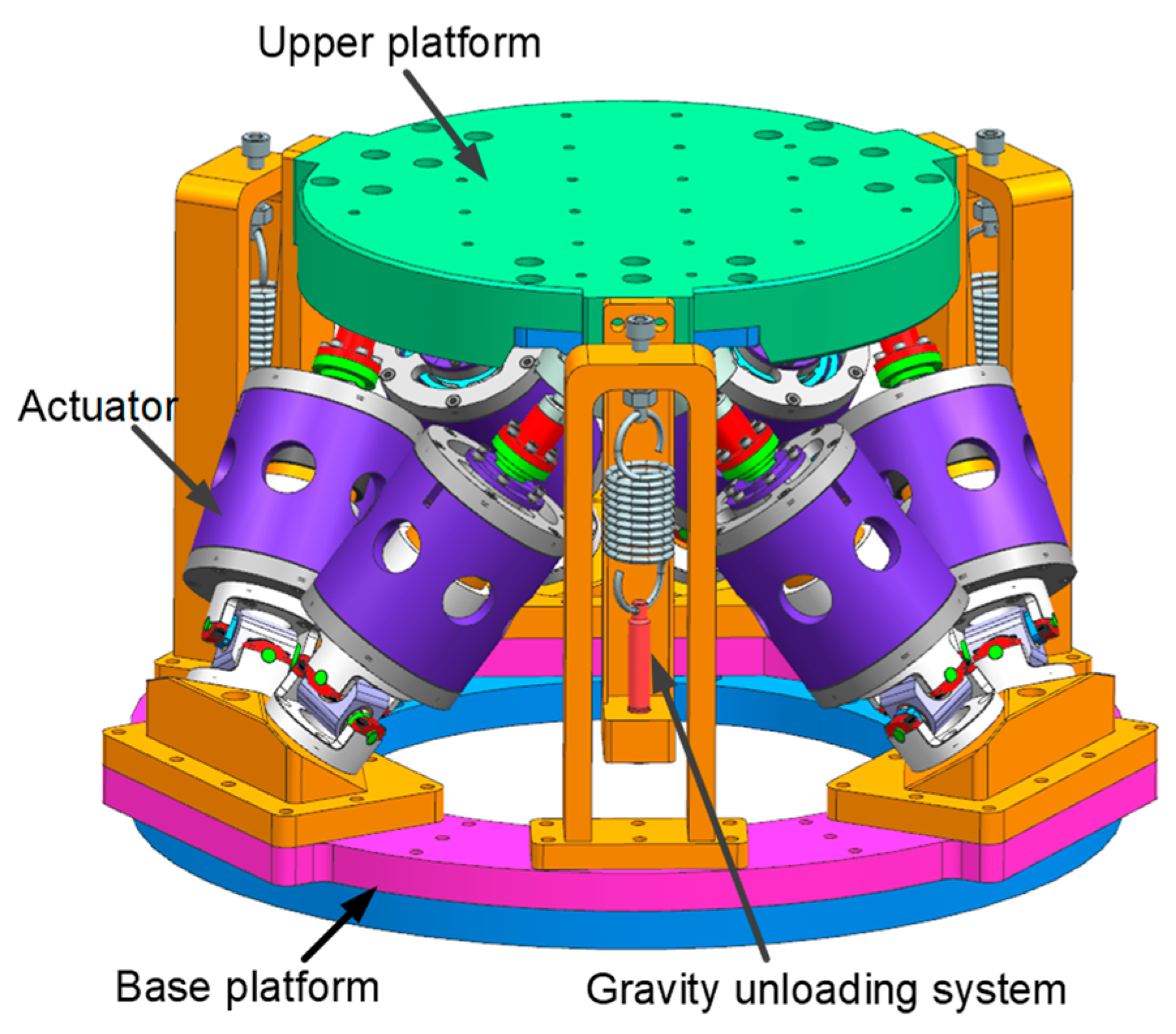
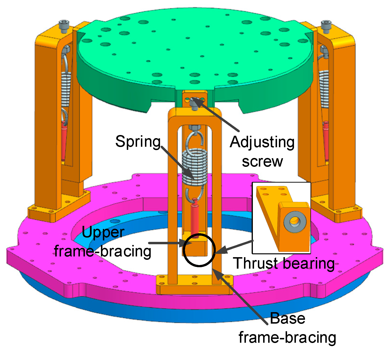
2.1. Structure Design
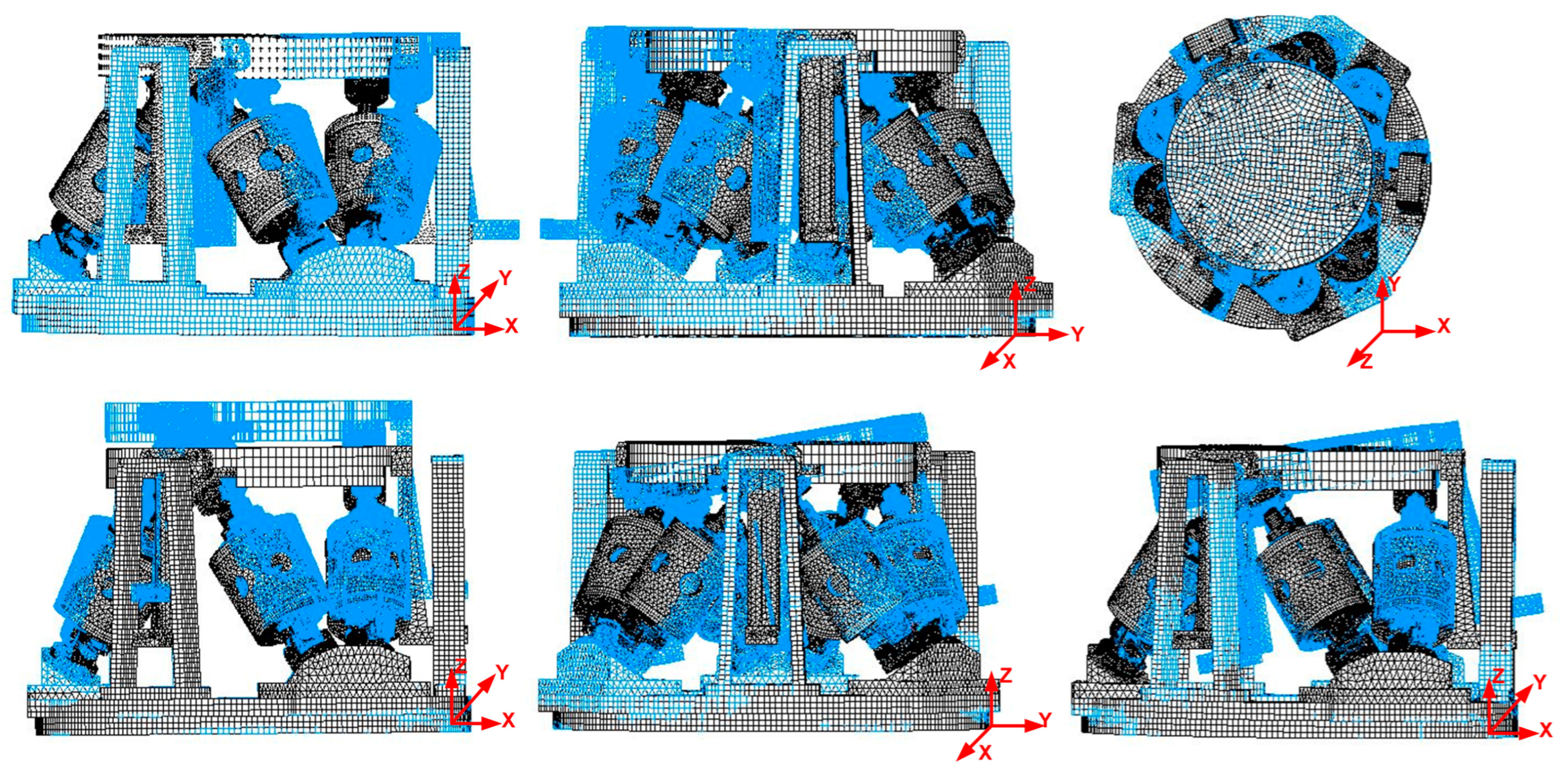
2.2. Simulation Analysis
3. Dynamic Model and Validation
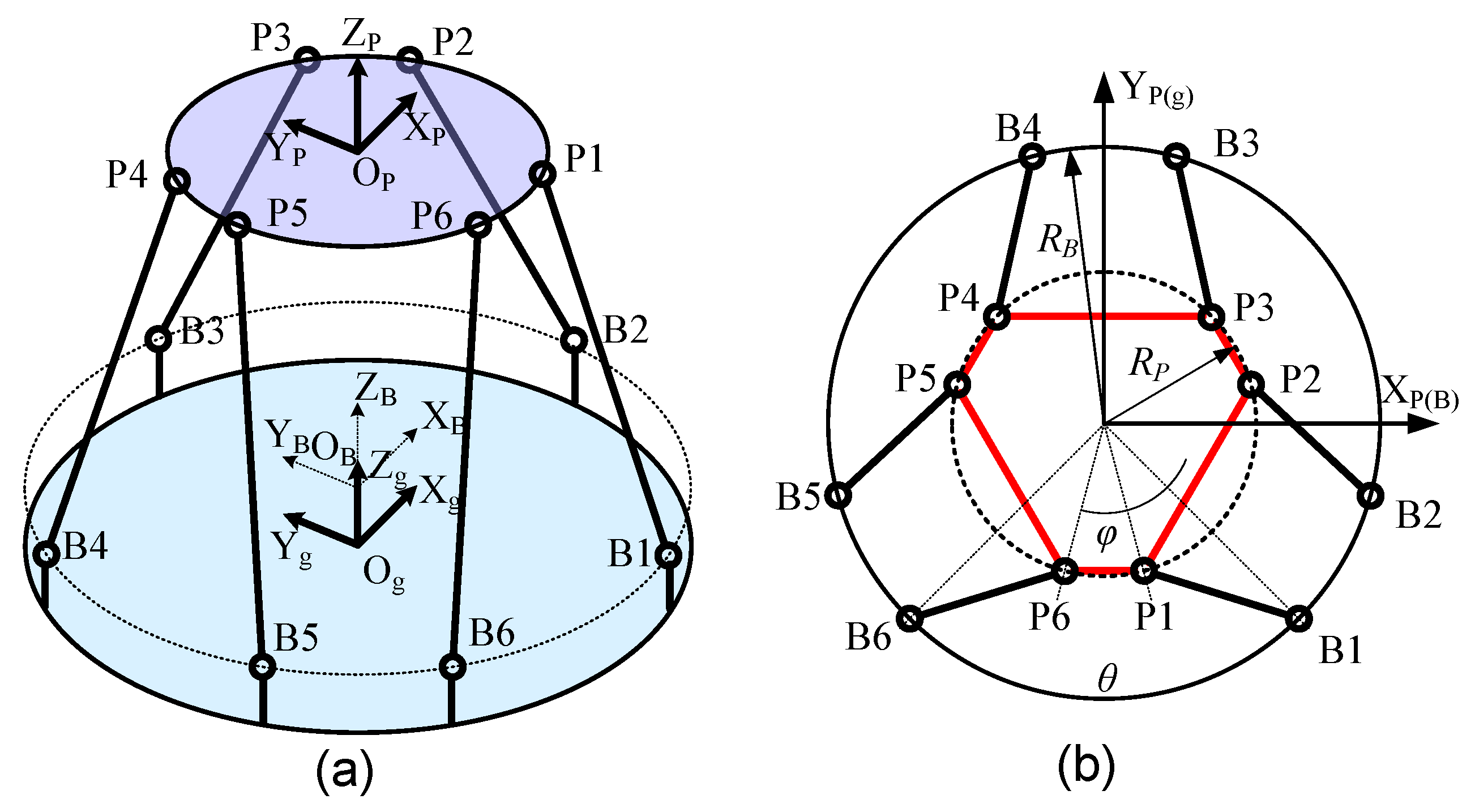
3.1. Complete Dynamic Equation
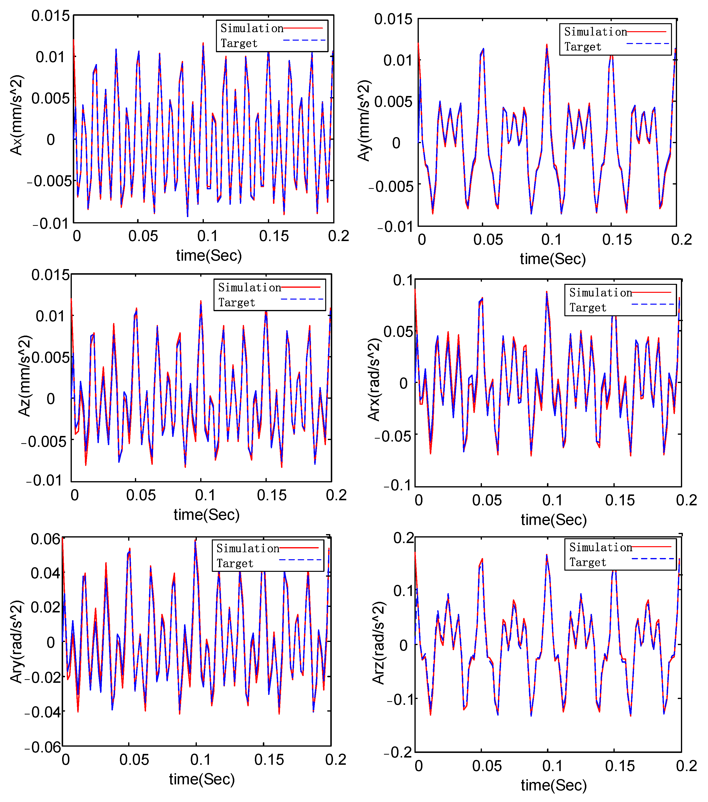
3.2. Co-Simulation Verification
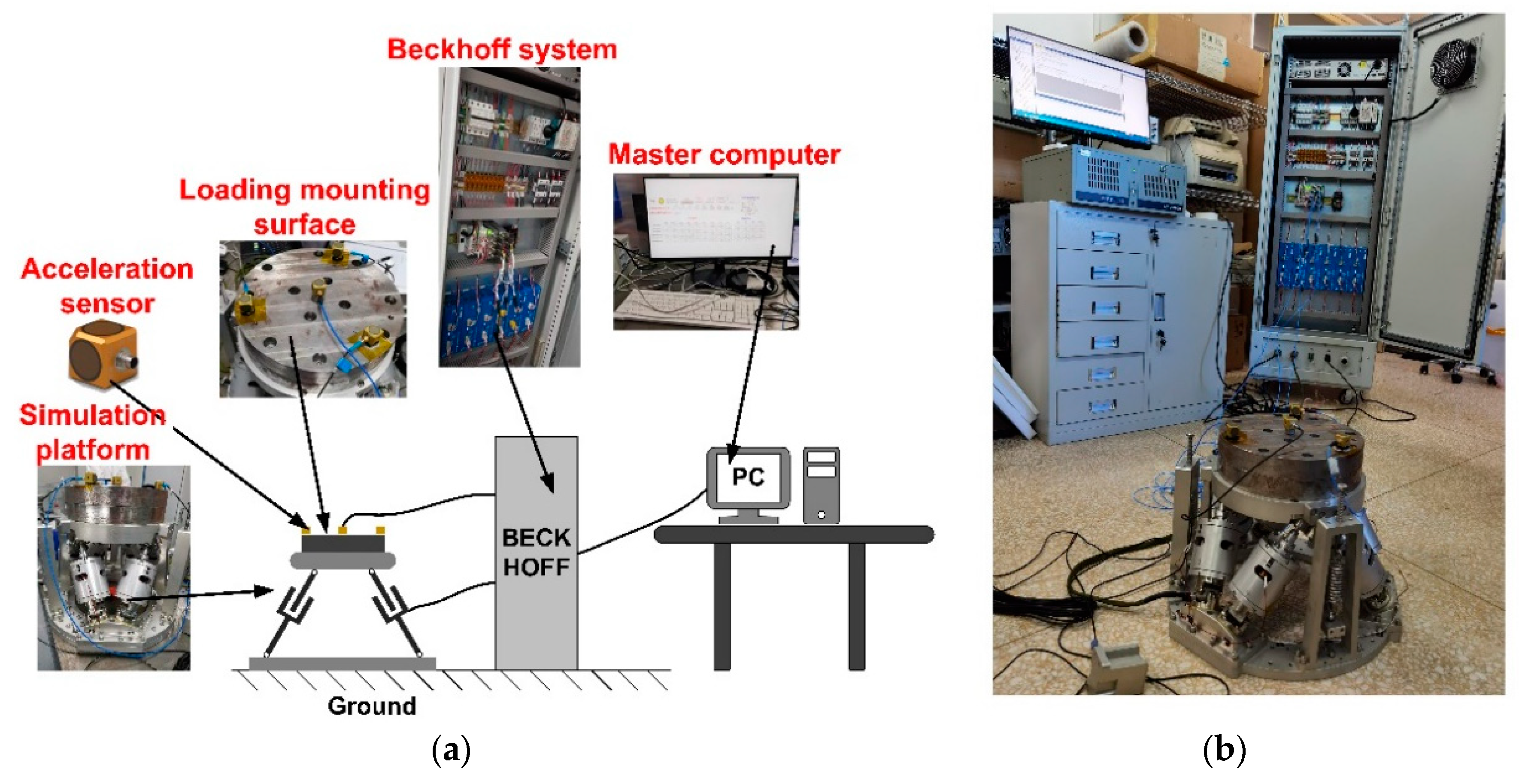
4. Experimental Section
4.1. Control Strategy
4.2. 6-DOF Micro-Vibration Test
5. Conclusions
Author Contributions
Funding
Data Availability Statement
Conflicts of Interest
References
- Iwata, T.; Yoshizawa, T.; Hoshino, H.; Maeda, K. Precision, Attitude and Orbit Control System for the Advanced Land Observing Satellite. In Proceedings of the Aiaa Guidance, Navigation, & Control Conference & Exhibit, Austin, TX, USA, 11–14 August 2003. [Google Scholar] [CrossRef]
- Liebe, C.C. Star trackers for attitude determination. IEEE Aerosp. Electron. Syst. Mag. 1995, 10, 10–16. [Google Scholar] [CrossRef]
- Kai, X.; Hong, Z. Performance evaluation of star sensor low frequency error calibration. Acta Astronaut. 2014, 98, 24–36. [Google Scholar] [CrossRef]
- Chandra, P.B.; Sarpotdar, M.; Nair, B.G.; Rai, R.; Mohan, R.; Mathew, J.; Safonova, M.; Murthy, J. Low-cost Raspberry Pi star sensor for small satellites. J. Astron. Telesc. Instrum. Syst. 2022, 8, 036002. [Google Scholar] [CrossRef]
- Toyoshima, M.; Takayama, Y.; Kunimori, H.; Jono, T.; Yamakawa, S. In-orbit measurements of spacecraft microvibrations for satellite laser communication links. Opt. Eng. 2010, 49, 578. [Google Scholar] [CrossRef]
- Kamesh, D.; Pandiyan, R.; Ghosal, A. Modeling, design and analysis of low frequency platform for attenuating micro-vibration in spacecraft. J. Sound Vib. 2010, 329, 3431–3450. [Google Scholar] [CrossRef]
- Sugimura, N.; Hashimoto, T.; Kuwahara, T.; Sakamoto, Y.; Takano, T. Improvement of Star Sensor in Generic Test Environment. Trans. Jpn. Soc. Aeronaut. Space Sci. Aerosp. Technol. Jpn. 2016, 14, Pf_97–Pf_103. [Google Scholar] [CrossRef]
- Ma, B.; Zong, Y.; Li, Z.; Li, Q.; Zhang, D.; Li, Y. Status and prospect of opto-mechanical integration analysis of micro-vibration in aerospace optical cameras. Opt. Precis. Eng. 2023, 31, 822–838. [Google Scholar] [CrossRef]
- Hostens, I.; Anthonis, J.; Kennes, P.; Ramon, H. Six-degrees-of-freedom test rig design for simulation of mobile agricultural machinery vibrations. J. Agric. Eng. Res. 2000, 77, 155–169. [Google Scholar] [CrossRef]
- Hostens, I.; Anthonis, J.; Ramon, H. New design for a 6 dof vibration simulator with improved reliability and performance. Mech. Syst. Signal Process. 2005, 19, 105–122. [Google Scholar] [CrossRef]
- Park, G.; Lee, D.O.; Han, J.H.; Goo, N.S. Development of multi-DOF active microvibration emulator. In Proceedings of the ASME Conference on Smart Materials, Adaptive Structures and Intelligent Systems, Stone Mountain, GA, USA, 19–21 September 2012; pp. 477–483. [Google Scholar] [CrossRef]
- Park, G.; Lee, D.O.; Han, J.H. Development of multi-degree-of-freedom microvibration emulator for efficient fitter test of spacecraft. J. Intell. Mater. Syst. Struct. 2014, 25, 1069–1081. [Google Scholar] [CrossRef]
- Wang, X.; He, S.; Xu, Z.; Li, H.; Sai, H.; Yang, J.; Li, L. A novel six-dimensional disturbance force and moment simulator for simulation of space micro-vibration environment. J. Vib. Control 2022, 29, 3646–3657. [Google Scholar] [CrossRef]
- Xu, Z.; Zhu, D.; He, S.; Shen, J.; Zhao, L.; Xia, M. Optimization of spatial micro-vibration simulation platform. Opt. Precis. Eng. 2019, 27, 2590–2601. [Google Scholar] [CrossRef]
- Schwartz, J.; Peck, M.; Hall, M. Historical Review of Air-Bearing Spacecraft Simulators. J. Guid. Control Dyn. 2003, 26, 513–522. [Google Scholar] [CrossRef]
- Sun, X.; Yang, B.; Zhao, L.; Sun, X. Optimal design and experimental analyses of a new micro-vibration control payload-platform. J. Sound Vib. 2016, 374, 43–60. [Google Scholar] [CrossRef]
- Janssen, J.; Paulides, J.; Lomonova, E.A.; Delinchant, B.; Yonnet, J.P. Design study on a magnetic gravity compensator with unequal magnet arrays. Mechatronics 2013, 23, 197–203. [Google Scholar] [CrossRef]
- Yang, G.; Wang, H.; Jiang, Y.; Ling, L.; Chang, Y.; Gao, F.; Yang, F. Gravity unloading precision analysis of air bearing facility. J. Mech. Eng. 2019, 55, 1–10. [Google Scholar] [CrossRef]
- Alessandro, S.; Emilia, W.; Guglielmo, A. Numerical and experimental validation of the breadboard model of a novel hexapod platform for high-performance micro-vibration mitigation. In Proceedings of the AIAA Scitech 2021 Forum, Virtual, 19–21 January 2021. [Google Scholar] [CrossRef]
- Chen, S.; Xuan, M.; Xin, J.; Liu, Y.; Gu, S.; Li, J.; Zhang, L. Design and experiment of dual micro-vibration isolation system for optical satellite flywheel. Int. J. Mech. Sci. 2020, 179, 105592. [Google Scholar] [CrossRef]
- Li, Q.; Zhao, W.; Shi, Z.; Wang, Y.; Liu, Z.; Yang, L. Research on positioning mechanism of optical device based on on-orbit replacement. Opt. Precis. Eng. 2019, 27, 2233–2240. [Google Scholar] [CrossRef]
- Ma, C.; Chen, L.; Liu, L.; Li, Q.; Yang, H. Development of Ultra-quiet Gravity Unloading for Micro-vibration Testing of Space Precision Payloads. In Proceedings of the 2021 IEEE 16th Conference on Industrial Electronics and Applications (ICIEA), Chengdu, China, 1–4 August 2021; IEEE: New York, NY, USA, 2021. [Google Scholar] [CrossRef]
- Zhu, H.; He, S.; Xu, Z.; Wang, X.; Qin, C.; Yang, J.; Zhang, L. Iterative feedback control based on frequency response model for a six-degree-of-freedom micro-vibration platform. J. Vib. Control 2022, 28, 1727–1738. [Google Scholar] [CrossRef]
- Paccot, F.; Andreff, N.; Martinet, P. A Review on the Dynamic Control of Parallel Kinematic Machines: Theory and Experiments. Int. J. Robot. Res. 2009, 28, 395–416. [Google Scholar] [CrossRef]
- Kim, H.S.; Cho, Y.M.; Lee, K. Robust nonlinear task space control for 6 DOF parallel manipulator. Automatica 2005, 41, 1591–1600. [Google Scholar] [CrossRef]
- Yang, J.; Xu, Z.; Wu, Q.; Zhu, M.; He, S.; Qin, C. Dynamic modeling and control of a 6-DOF micro-vibration simulator. Mech. Mach. Theory 2016, 104, 350–369. [Google Scholar] [CrossRef]
- Zhou, W.; Li, D.; Luo, Q.; Liu, K. Analysis and testing of microvibrations produced by momentum wheel assemblies. Chin. J. Aeronaut. 2012, 25, 640–649. [Google Scholar] [CrossRef]


| Order | Frequency (Hz) | Description of Vibration Pattern |
|---|---|---|
| 1 | 1.6473 | Translation in the X-axis direction |
| 2 | 1.6473 | Translation in the Y-axis direction |
| 3 | 2.3519 | Rotation in the Z-axis direction |
| 4 | 3.7542 | Translation in the Z-axis direction |
| 5 | 4.1668 | Rotation in the X-axis direction |
| 6 | 4.1669 | Rotation in the Y-axis direction |
| Frequency (Hz) | Ax (mm∙s−2) | Ay (mm∙s−2) | Az (mm∙s−2) | Arx (rad∙s−2) | Ary (rad∙s−2) | Arz (rad∙s−2) |
|---|---|---|---|---|---|---|
| 40 | 1.0 | 5.0 | 2.0 | 0.03 | 0.01 | 0.08 |
| 60 | 3.0 | 4.0 | 4.0 | 0.02 | 0.02 | 0.04 |
| 120 | 8.0 | 3.0 | 6.0 | 0.04 | 0.03 | 0.05 |
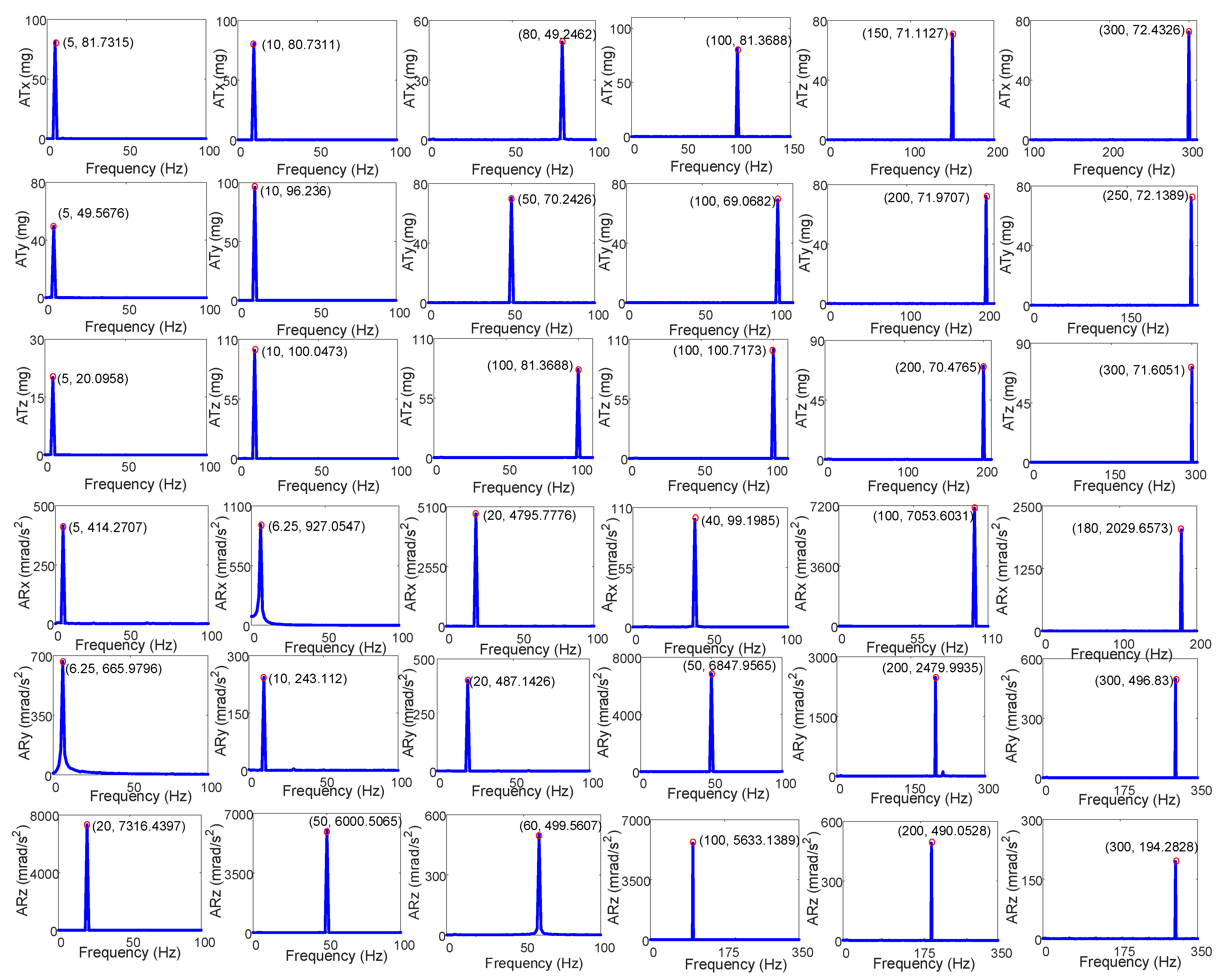
| Direction | Frequency (Hz) | Target Acceleration (mg) | Actual Acceleration (mg) | Magnitude Error (%) |
|---|---|---|---|---|
| x | 5 | 90 | 81.73 | 9.19 |
| x | 10 | 80 | 80.73 | 0.91 |
| x | 80 | 50 | 49.25 | 1.50 |
| x | 100 | 80 | 81.37 | 1.71 |
| x | 150 | 70 | 71.11 | 1.59 |
| x | 300 | 70 | 72.43 | 3.47 |
| y | 5 | 50 | 49.57 | 0.86 |
| y | 10 | 95 | 96.24 | 1.31 |
| y | 50 | 70 | 70.24 | 0.34 |
| y | 100 | 70 | 69.07 | 1.33 |
| y | 200 | 70 | 71.97 | 2.81 |
| y | 250 | 70 | 72.14 | 3.06 |
| z | 5 | 20 | 20.10 | 0.50 |
| z | 10 | 100 | 100.05 | 0.05 |
| z | 100 | 80 | 81.37 | 1.71 |
| z | 100 | 100 | 100.71 | 0.71 |
| z | 250 | 70 | 70.48 | 0.69 |
| z | 300 | 70 | 71.61 | 2.30 |
| Direction | Frequency (Hz) | Target Acceleration (mrad/s2) | Actual Acceleration (mrad/s2) | Magnitude Error (%) |
|---|---|---|---|---|
| rx | 5 | 400 | 414.27 | 3.57 |
| rx | 6 | 1000 | 927.05 | 7.30 |
| rx | 20 | 5000 | 4975.78 | 0.48 |
| rx | 40 | 100 | 99.20 | 0.8 |
| rx | 100 | 7000 | 7053.60 | 0.77 |
| rx | 180 | 2000 | 2029.66 | 1.48 |
| ry | 6 | 700 | 665.98 | 4.86 |
| ry | 10 | 250 | 243.11 | 2.76 |
| ry | 20 | 500 | 487.14 | 2.57 |
| ry | 50 | 7000 | 6847.96 | 2.17 |
| ry | 200 | 2500 | 2479.99 | 0.8 |
| ry | 300 | 500 | 496.83 | 0.64 |
| rz | 20 | 7000 | 7316.44 | 4.52 |
| rz | 50 | 6000 | 6000.51 | 0.01 |
| rz | 60 | 500 | 499.56 | 0.01 |
| rz | 100 | 6000 | 5633.14 | 6.11 |
| rz | 200 | 500 | 490.05 | 1.99 |
| rz | 300 | 200 | 194.28 | 2.86 |
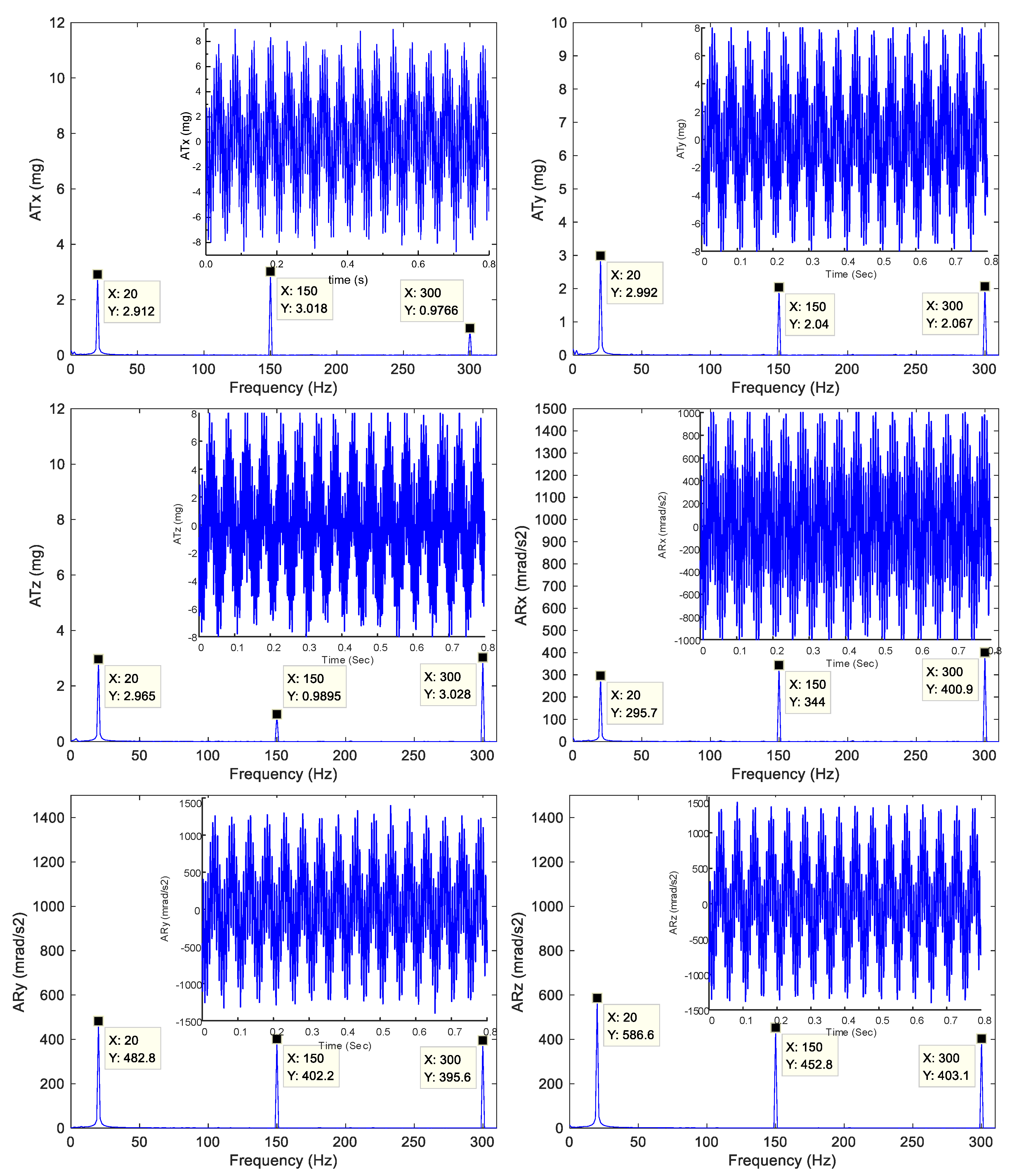
| Frequency | Tx (mg) | Ty (mg) | Tz (mg) | Rx (mrad/s2) | Ry (mrad/s2) | Rz (mrad/s2) | |
|---|---|---|---|---|---|---|---|
| 20 Hz | Target acceleration | 3 | 3 | 3 | 300 | 500 | 600 |
| Actul acceleration | 2.91 | 2.99 | 2.97 | 295.7 | 482.8 | 586.6 | |
| Magnitude error (%) | 3.00 | 0.33 | 1.00 | 1.43 | 3.44 | 2.23 | |
| 150 Hz | Target acceleration | 3 | 2 | 1 | 350 | 400 | 450 |
| Actul acceleration | 3.02 | 2.04 | 0.99 | 344.0 | 402.2 | 452.8 | |
| Magnitude error (%) | 0.67 | 2.00 | 1.00 | 1.71 | 0.55 | 0.62 | |
| 300 Hz | Target acceleration | 1 | 2 | 3 | 400 | 400 | 400 |
| Actul acceleration | 0.98 | 2.07 | 3.03 | 400.9 | 395.6 | 403.1 | |
| Magnitude error (%) | 2.00 | 3.50 | 1.00 | 0.23 | 1.10 | 0.78 |
Disclaimer/Publisher’s Note: The statements, opinions and data contained in all publications are solely those of the individual author(s) and contributor(s) and not of MDPI and/or the editor(s). MDPI and/or the editor(s) disclaim responsibility for any injury to people or property resulting from any ideas, methods, instructions or products referred to in the content. |
© 2023 by the authors. Licensee MDPI, Basel, Switzerland. This article is an open access article distributed under the terms and conditions of the Creative Commons Attribution (CC BY) license (https://creativecommons.org/licenses/by/4.0/).
Share and Cite
Zhu, H.; He, S.; Wang, X.; Qin, C.; Li, L.; Sun, X. Design and Testing of a Simulator for Micro-Vibration Testing of Star Sensor. Micromachines 2023, 14, 1652. https://doi.org/10.3390/mi14091652
Zhu H, He S, Wang X, Qin C, Li L, Sun X. Design and Testing of a Simulator for Micro-Vibration Testing of Star Sensor. Micromachines. 2023; 14(9):1652. https://doi.org/10.3390/mi14091652
Chicago/Turabian StyleZhu, He, Shuai He, Xiaoming Wang, Chao Qin, Lin Li, and Xiangyang Sun. 2023. "Design and Testing of a Simulator for Micro-Vibration Testing of Star Sensor" Micromachines 14, no. 9: 1652. https://doi.org/10.3390/mi14091652
APA StyleZhu, H., He, S., Wang, X., Qin, C., Li, L., & Sun, X. (2023). Design and Testing of a Simulator for Micro-Vibration Testing of Star Sensor. Micromachines, 14(9), 1652. https://doi.org/10.3390/mi14091652