
Design of Plasmonic Photonic Crystal Fiber for Highly Sensitive Magnetic Field and Temperature Simultaneous Measurement

Abstract
:1. Introduction
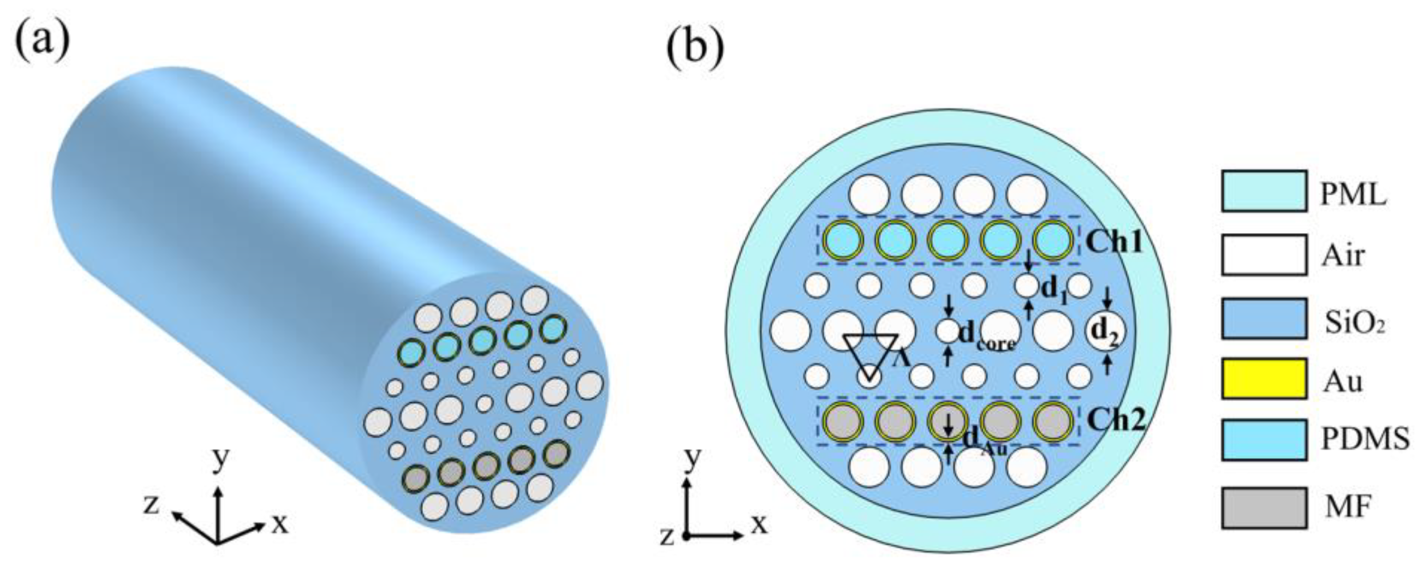
2. Model and Theory
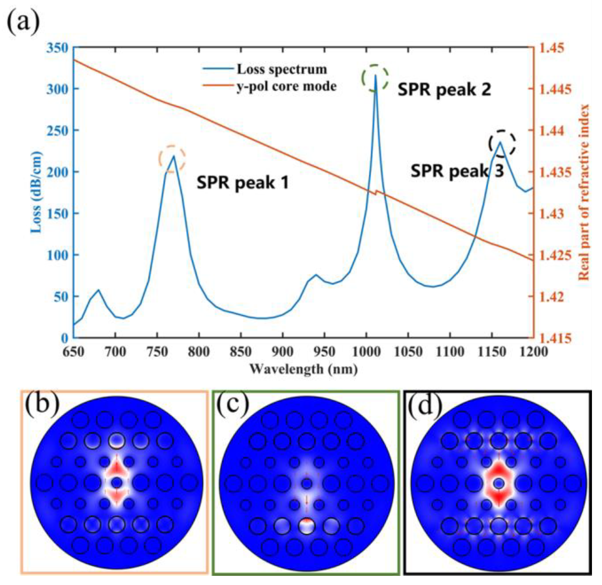
3. Analysis Mode Characteristics
4. Analysis of Structural Parameters
4.1. The Gold Film Thickness
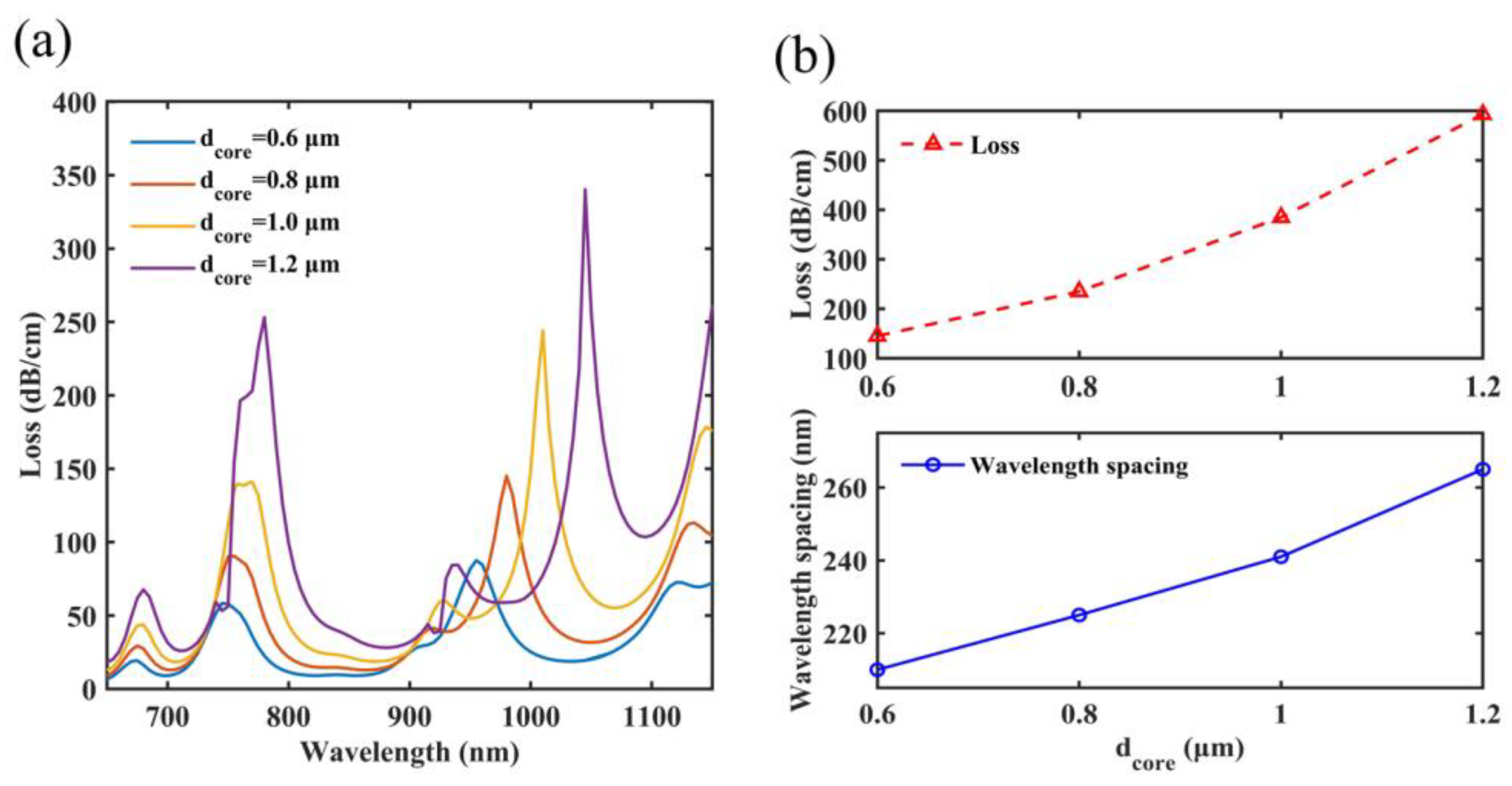
4.2. The Diameter of the Central Air Hole
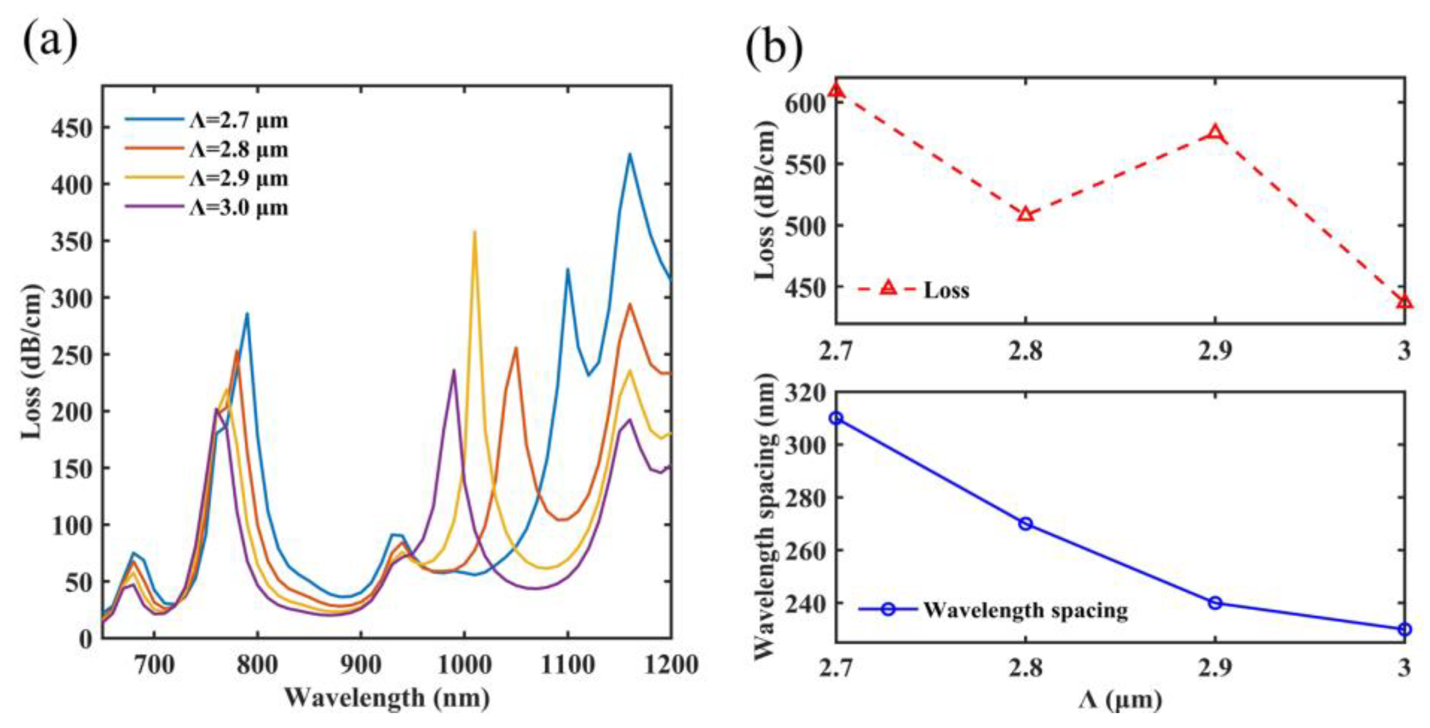
4.3. The Pitch of the Air Hole
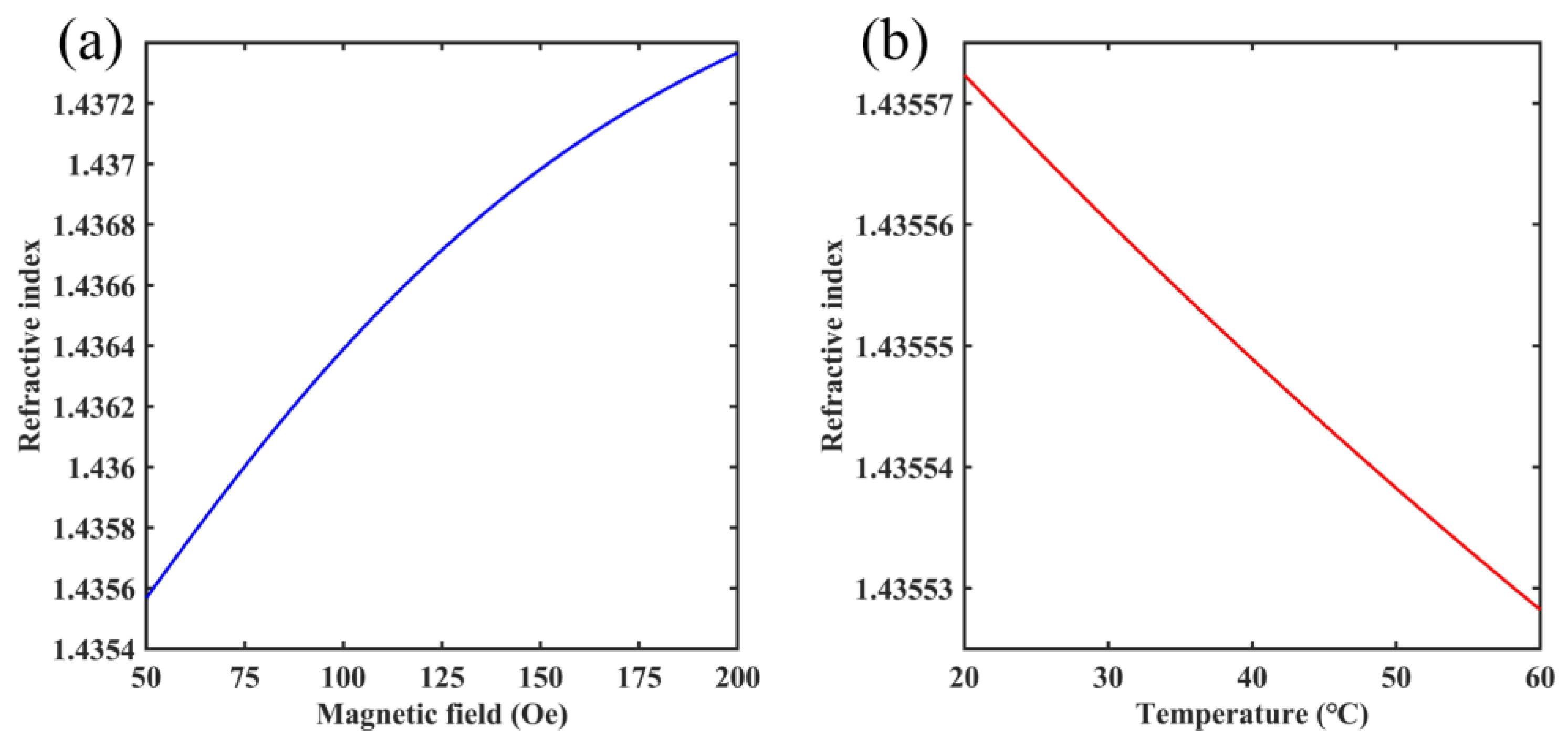
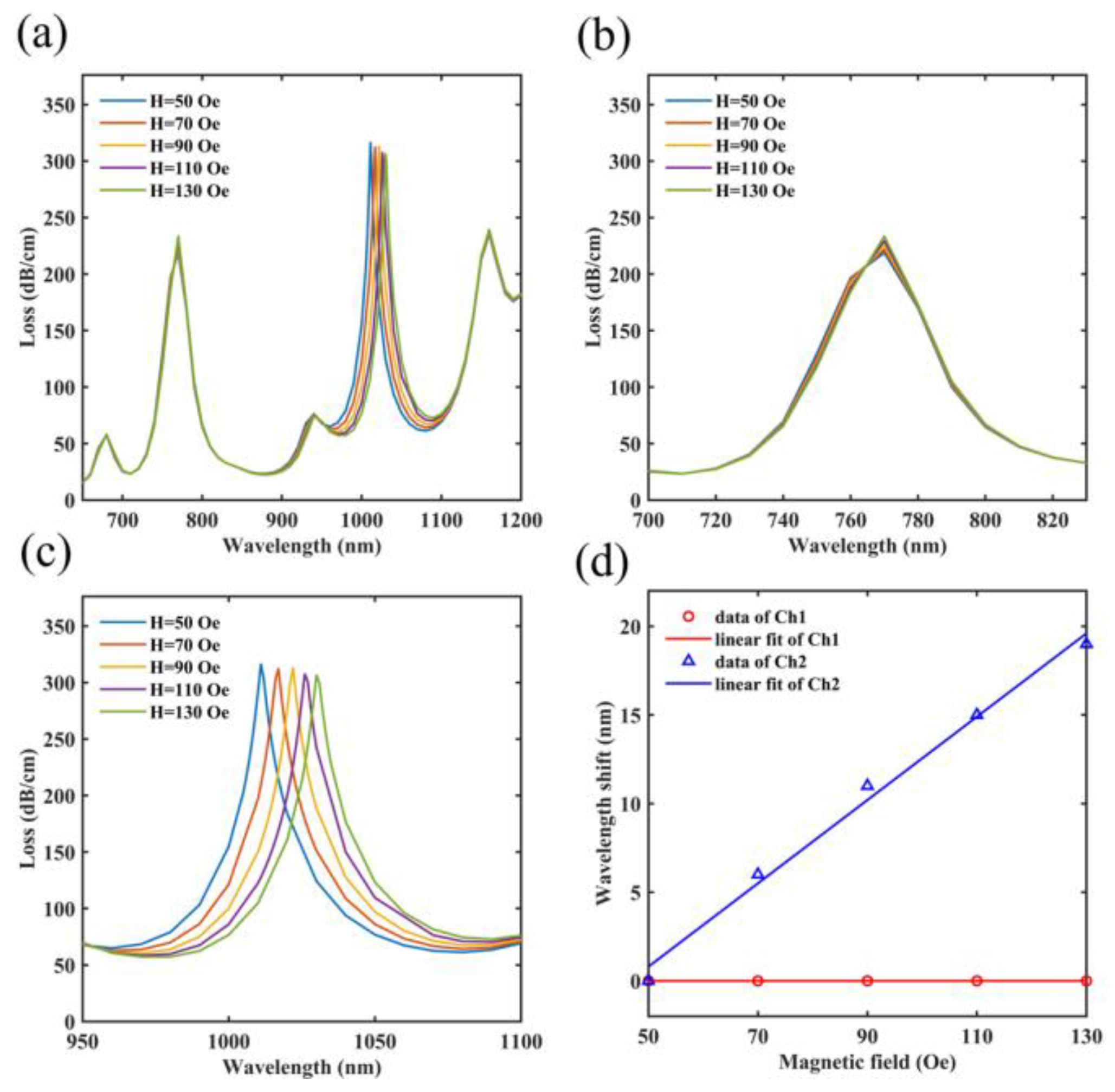
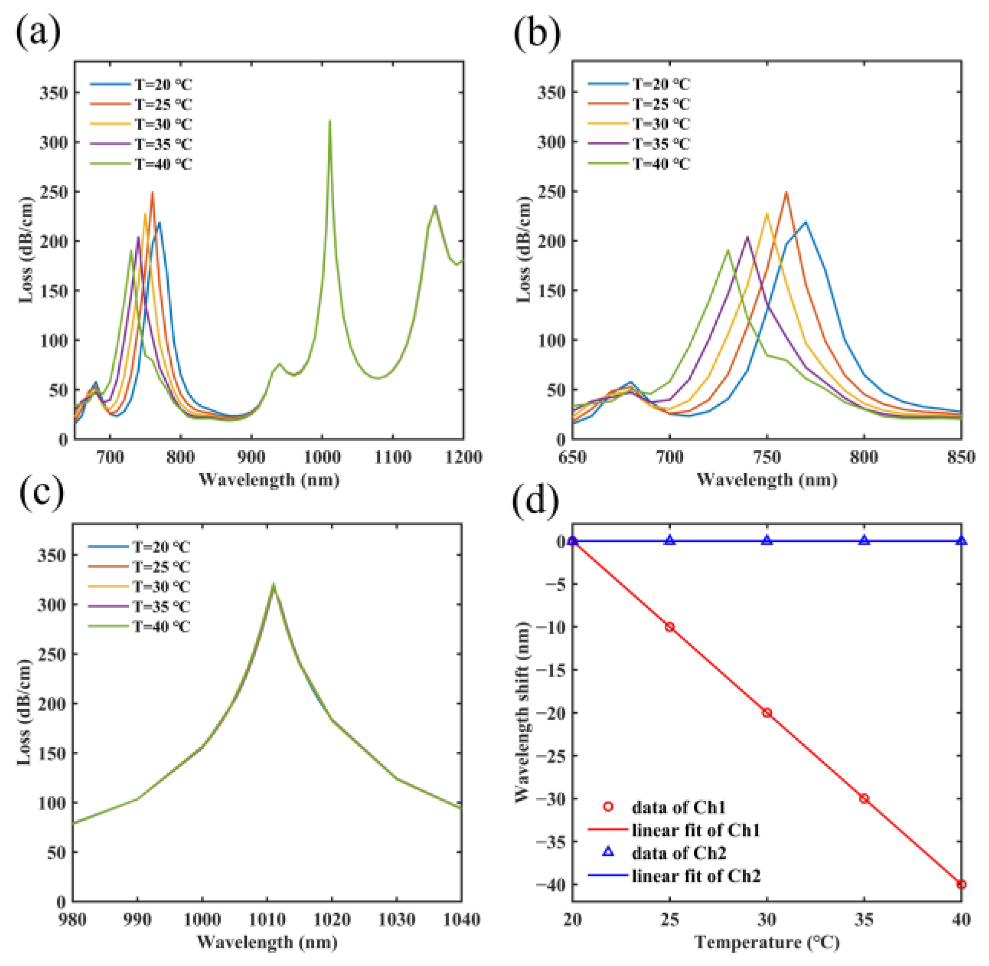
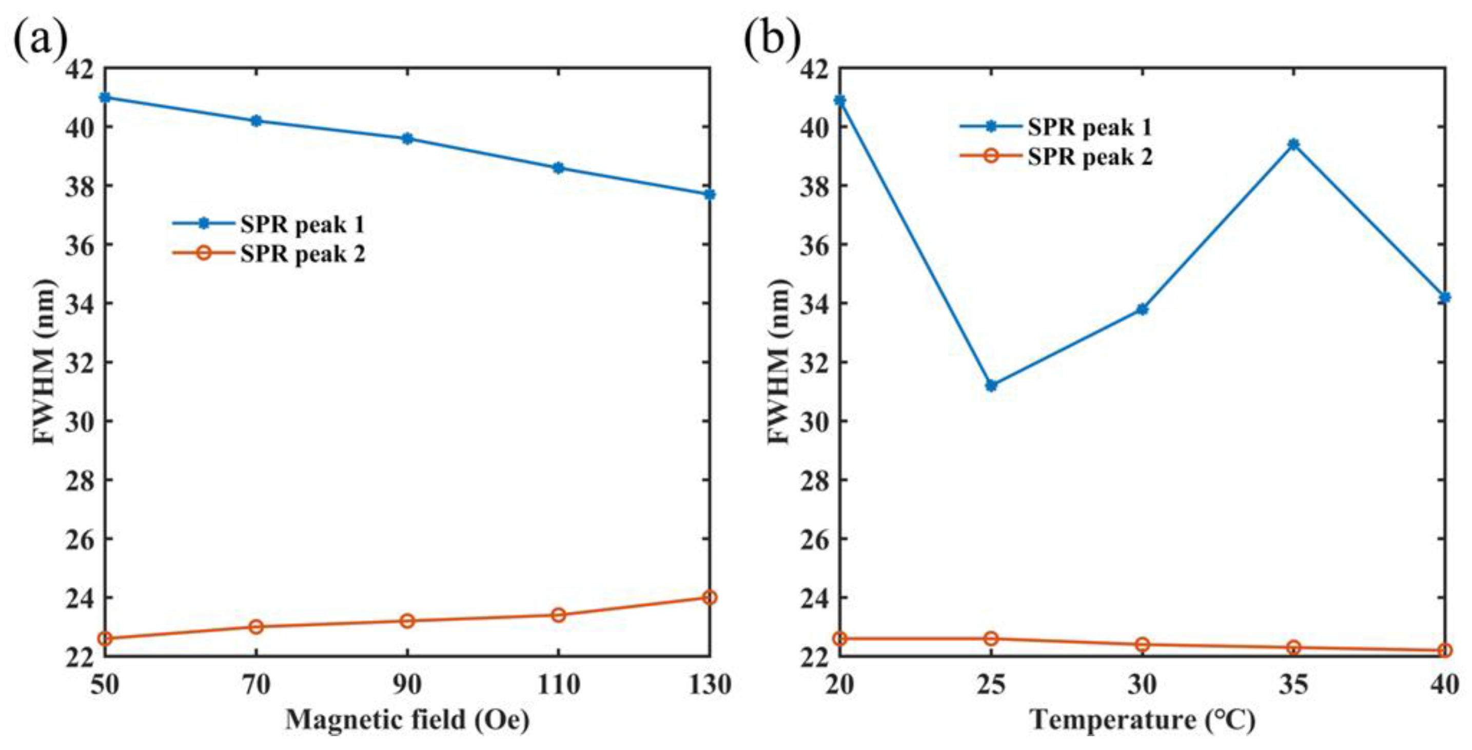
5. Measurement of Magnetic Field and Temperature
6. Conclusions
Author Contributions
Funding
Institutional Review Board Statement
Informed Consent Statement
Data Availability Statement
Conflicts of Interest
References
- Lai, R.; Shi, P.; Yi, Z.; Li, H.; Yi, Y. Triple-Band Surface Plasmon Resonance Metamaterial Absorber Based on Open-Ended Prohibited Sign Type Monolayer Graphene. Micromachines 2023, 14, 953. [Google Scholar]
- Jia, Z.; Huang, L.; Su, J.; Tang, B. Tunable electromagnetically induced transparency-like in graphene metasurfaces and its application as a refractive index sensor. J. Light. Technol. 2021, 39, 1544–1549. [Google Scholar] [CrossRef]
- Shangguan, Q.; Chen, Z.; Yang, H.; Cheng, S.; Yang, W.; Yi, Z.; Wu, X.; Wang, S.; Yi, Y.; Wu, P. Design of Ultra-Narrow Band Graphene Refractive Index Sensor. Sensors 2022, 22, 6483. [Google Scholar] [CrossRef]
- Ye, Z.; Wu, P.; Wang, H.; Jiang, S.; Huang, M.; Lei, D.; Wu, F. Multimode tunable terahertz absorber based on a quarter graphene disk structure. Results Phys. 2023, 48, 106420. [Google Scholar] [CrossRef]
- Ma, J.; Wu, P.H.; Li, W.X.; Liang, S.R.; Shangguan, Q.Y.; Cheng, S.B.; Tian, Y.H.; Fu, J.Q.; Zhang, L.B. A five-peaks graphene absorber with multiple adjustable and high sensitivity in the far infrared band. Results Phys. 2023, 136, 109960. [Google Scholar] [CrossRef]
- Liu, W.; Liu, C.; Wang, J.X.; Lv, J.W.; Lv, Y.; Yang, L.; An, N.; Yi, Z.; Liu, Q.; Hu, C.J.; et al. Surface plasmon resonance sensor composed of microstructured optical fibers for monitoring of external and internal environments in biological and environmental sensing. Results Phys. 2023, 47, 106365. [Google Scholar] [CrossRef]
- Jiang, L.Y.; Yi, Y.T.; Yi, Z.; Yang, H.; Li, Z.Y.; Su, J.; Zhou, Z.G.; Chen, X.F.; Yi, Y.G. A four-band perfect absorber based on high quality factor and high figure of merit of monolayer molybdenum disulfide. Acta Phys. Sin. 2021, 70, 128101. [Google Scholar] [CrossRef]
- Ren, Y.; Tang, B. Switchable Multi-Functional VO2-Integrated Metamaterial Devices in the Terahertz Region. J. Light. Technol. 2021, 39, 5864–5868. [Google Scholar] [CrossRef]
- Li, J.; Liu, G.; Liu, B.; Min, Z.; Qian, D.; Jiang, J.; Li, J. An extremely facile route to Co2P encased in N,P-codoped carbon layers: Highly efficient bifunctional electrocatalysts for ORR and OER. Int. J. Hydrogen Energy 2018, 43, 1365–1374. [Google Scholar] [CrossRef]
- Wu, X.; Tan, C.; He, C.; Zhao, T.; Wu, X.; Ma, Z.; Wang, H.; Cai, Y.; Wu, Q.; Li, Q. Strategy for boosting Co-Nx content for oxygen reduction reaction in aqueous metal-air batteries. J. Power Source 2022, 520, 230891. [Google Scholar] [CrossRef]
- Schulz, L.; Heinisch, P.; Richter, I. Calibration of off-the-shelf anisotropic magnetoresistance magnetometers. Sensors 2019, 19, 1850. [Google Scholar] [CrossRef]
- Zhu, Y.Y.; Cai, P.G.; Zhang, W.L.; Meng, T.Y.; Tang, Y.J.; Yi, Z.; Wei, K.H.; Li, G.F.; Tang, B.; Yi, Y.G. Ultra-Wideband High-Efficiency Solar Absorber and Thermal Emitter Based on Semiconductor InAs Microstructures. Micromachines 2023, 14, 1597. [Google Scholar] [CrossRef]
- Chen, Z.H.; Cai, P.G.; Wen, Q.Y.; Chen, H.; Tang, Y.J.; Yi, Z.; Wei, K.H.; Li, G.F.; Tang, B.; Yi, Y.G. Graphene Multi-Frequency Broadband and Ultra-Broadband Terahertz Absorber Based on Surface Plasmon Resonance. Electronics 2023, 12, 2655. [Google Scholar] [CrossRef]
- Tang, B.; Li, Z.; Palacios, E.; Liu, Z.; Butun, S.; Aydin, K. Chiral-Selective Plasmonic Metasurface Absorbers Operating at Visible Frequencies. IEEE Photonics Technol. Lett. 2017, 29, 295–298. [Google Scholar] [CrossRef]
- Zhu, W.L.; Xu, F.; Yi, Z.; Cheng, S.B.; Yang, H.; Wu, X.W.; Li, G.F.; Zeng, L.C.; Yu, Z.F.; Li, H.L. Highly sensitive plasmonic sensor based on eccentric-core photonic crystal fibers. Phys. Chem. Chem. Phys. 2023, 25, 19596. [Google Scholar] [CrossRef]
- Sun, L.; Jiang, S.; Marciante, J. All-fiber optical magnetic-field sensor based on Faraday rotation in highly terbium-doped fiber. Opt. Express 2010, 18, 5407–5412. [Google Scholar] [CrossRef]
- Shiyu, Y.; Lousteau, J.; Olivero, M.; Merlo, M.; Boetti, N.; Abrate, S.; Chen, Q.; Chen, Q.; Milanese, D. Analysis of Faraday effect in multimode tellurite glass optical fiber for magneto-optical sensing and monitoring applications. Appl. Opt. 2012, 51, 4542–4546. [Google Scholar] [CrossRef]
- Zhan, B.; Ning, T.; Pei, L.; Li, J.; Liu, L.; Gao, X.; Xu, J.; Zheng, J.; Wang, J.; Ai, B. Terfenol-D based magnetic field sensor with temperature independence incorporating dual fiber Bragg gratings structure. IEEE Access 2021, 9, 32713–32720. [Google Scholar] [CrossRef]
- Peng, J.; Zhang, S.; Jia, S.; Kang, X.; Yu, H.; Yang, S.; Wang, S.; Yang, Y. A highly sensitive magnetic field sensor based on FBG and magnetostrictive composite with oriented magnetic domains. Measurement 2022, 189, 110667. [Google Scholar] [CrossRef]
- Zhao, Y.; Lv, R.Q.; Ying, Y.; Wang, Q. Hollow-core photonic crystal fiber Fabry–Perot sensor for magnetic field measurement based on magnetic fluid. Opt. Laser Technol. 2012, 44, 899–902. [Google Scholar] [CrossRef]
- Luo, L.; Pu, S.; Dong, S.; Tang, J. Fiber-optic magnetic field sensor using magnetic fluid as the cladding. Sens. Actuators A Phys. 2015, 236, 67–72. [Google Scholar] [CrossRef]
- Tang, B.; Jia, Z.; Huang, L.; Su, J.; Jiang, C. Polarization-Controlled Dynamically Tunable Electromagnetically Induced Transparency-Like Effect Based on Graphene Metasurfaces. IEEE J. Sel. Top. Quantum Electron. 2021, 27, 4700406. [Google Scholar] [CrossRef]
- Liang, S.R.; Xu, F.; Li, W.X.; Yang, W.X.; Cheng, S.B.; Yang, H.; Chen, J.; Yi, Z.; Jiang, P.P. Tunable smart mid infrared thermal control emitter based on phase change material VO2 thin film. Appl. Therm. Eng. 2023, 232, 121074. [Google Scholar] [CrossRef]
- Qin, F.; Chen, J.; Liu, J.W.; Liu, L.; Tang, C.J.; Tang, B.; Li, G.F.; Zeng, L.C.; Li, H.L.; Yi, Z. Design of high efficiency perovskite solar cells based on inorganic and organic undoped double hole layer. Sol. Energy 2023, 262, 111796. [Google Scholar] [CrossRef]
- Ren, Y.; Zhou, T.L.; Jiang, C.; Tang, B. Thermally switching between perfect absorber and asymmetric transmission in vanadium dioxide-assisted metamaterials. Opt. Express 2021, 29, 7666–7679. [Google Scholar] [CrossRef]
- Zhao, Z.H.; Wang, Q. Gold nanoparticles (AuNPs) and graphene oxide heterostructures with gold film coupling for an enhanced sensitivity surface plasmon resonance (SPR) fiber sensor. Instrum. Sci. Technol. 2022, 50, 530–542. [Google Scholar] [CrossRef]
- Zhu, Y.; Tang, B.; Yang, N.; Lang, X.; Su, J.; Li, Z. Tunable wide-angle perfect absorber based on black phosphorous-dielectric-metallic hybrid architecture. Physica E 2021, 126, 114449. [Google Scholar] [CrossRef]
- Zhu, W.; Yi, Y.; Yi, Z.; Bian, L.; Yang, H.; Zhang, J.; Yu, Y.; Liu, C.; Li, G.; Wu, X. High confidence plasmonic sensor based on photonic crystal fiber with U-shaped detection channel. Phys. Chem. Chem. Phys. 2023, 25, 8583. [Google Scholar] [CrossRef]
- Li, W.; Yi, Y.; Yang, H.; Cheng, S.; Yang, W.X.; Zhang, H.; Yi, Z.; Yi, Y.; Li, H. Active Tunable Terahertz Bandwidth Absorber Based on single layer Graphene. Commun. Theor. Phys. 2023, 75, 045503. [Google Scholar] [CrossRef]
- Liu, Y.Y.; Wang, Z.; Li, L.J.; Gao, S.F.; Zheng, D.S.; Yu, X.X.; Wu, Q.F.; Yang, Q.; Zhu, D.S.; Yang, W.X.; et al. Highly efficient quantum-dot-sensitized solar cells with composite semiconductor of ZnO nanorod and oxide inverse opal in photoanode. Electrochim. Acta 2022, 412, 140145. [Google Scholar] [CrossRef]
- Wu, X.; Yin, C.; Zhang, M.; Xie, Y.; Hu, J.; Long, R.; Wu, X.; Wu, X. The Intercalation Cathode of MOFs-driven Vanadium-based Composite Embedded in N-doped Carbon for Aqueous Zinc ion Batteries. Chem. Eng. J. 2023, 452, 139573. [Google Scholar] [CrossRef]
- Meng, W.; Li, C.; Yao, M.; He, Z.; Wu, X.; Jiang, Z.; Dai, L.; Wang, L. Synthesis and electrochemical performance of Li1+xTi2−xFex(PO4)3/C anode for aqueous lithium ion battery. Adv. Powder Technol. 2020, 31, 1359–1364. [Google Scholar] [CrossRef]
- Wu, X.; Li, Y.; Xiang, Y.; Liu, Z.; He, Z.; Wu, X.; Li, Y.; Xiong, L.; Li, C.; Chen, J. Mixed-valence cobalt oxides bifunctional electrocatalyst with rich oxygen vacancies for aqueous metal-air batteries. Chem. Eng. J. 2023, 453, 139831. [Google Scholar] [CrossRef]
- Tang, F.; Wu, X.; Shen, Y.; Xiang, Y.; Wu, X.; Xiong, L.; Wu, X. The intercalation cathode materials of heterostructure MnS/MnO with dual ions defect embedded in N-doped carbon fibers for aqueous zinc ion batteries. Energy Storage Mater. 2022, 52, 180–188. [Google Scholar] [CrossRef]
- Li, C.; Shi, X.; Liang, S.; Ma, X.; Han, M.; Wu, X.; Zhou, J. Spatially homogeneous copper foam as surface dendrite-free host for zinc metal anode. Chem. Eng. J. 2020, 379, 122248. [Google Scholar] [CrossRef]
- Li, Y.; Yang, S.; Du, H.; Liu, Y.; Wu, X.; Yin, C.; Wang, D.; Wu, X.; He, Z.; Wu, X. A stable fluoride-based interphase for a long cycle Zn metal anode in an aqueous zinc ion battery. J. Mater. Chem. A 2022, 10, 14399–14410. [Google Scholar] [CrossRef]
- Zheng, Y.; Yi, Z.; Liu, L.; Wu, X.W.; Liu, H.; Li, G.F.; Zeng, L.C.; Li, H.L.; Wu, P.H. Numerical simulation of efficient solar absorbers and thermal emitters based on multilayer nanodisk arrays. Appl. Therm. Eng. 2023, 230, 120841. [Google Scholar] [CrossRef]
- Tang, B.; Ren, Y. Tunable and switchable multi-functional terahertz metamaterials based on a hybrid vanadium dioxide–graphene integrated configuration. Phys. Chem. Chem. Phys. 2022, 24, 8408–8414. [Google Scholar] [CrossRef]
- Zhu, L.; Hu, R.; Xiang, Y.; Yang, X.; Chen, Z.; Xiong, L.; Wu, X.; He, Z.; Lei, W. Enhanced performance of Li-S battery by constructing inner conductive network and outer adsorption layer sulfur-carbon composite. Int. J. Energy Res. 2020, 45, 6002–6014. [Google Scholar] [CrossRef]
- Qi, H.N.; Tang, B. Active tunable terahertz functional metamaterial based on hybrid-graphene vanadium dioxide. Phys. Chem. Chem. Phys. 2023, 25, 7825–7831. [Google Scholar] [CrossRef]
- Chen, H.; Li, W.; Zhu, S.M.; Hou, A.Q.; Liu, T.; Xu, J.S.; Zhang, X.W.; Yi, Z.; Yi, Y.G.; Dai, B. Study on the Thermal Distribution Characteristics of a Molten Quartz Ceramic Surface under Quartz Lamp Radiation. Micromachines 2023, 14, 1231. [Google Scholar] [CrossRef] [PubMed]
- Wu, X.; Li, Y.; Xiang, Y.; Liu, Z.; He, Z.; Wu, X.; Li, Y.; Xiong, L.; Li, C.; Chen, J. The electrochemical performance of aqueous rechargeable battery of Zn/Na0.44MnO2 based on hybrid electrolyte. J. Power Source 2016, 336, 35–39. [Google Scholar] [CrossRef]
- Tang, B.; Guo, Z.; Jin, G. Polarization-controlled and symmetry-dependent multiple plasmon-induced transparency in graphene-based metasurfaces. Opt. Express 2022, 30, 35554–35566. [Google Scholar] [CrossRef]
- Li, W.X.; Zhao, W.C.; Cheng, S.B.; Yang, W.X.; Yi, Z.; Li, G.F.; Zeng, L.C.; Li, H.L.; Wu, P.H.; Cai, S.S. Terahertz Selective Active Electromagnetic Absorption Film Based on Single-layer Graphene. Surf. Interfaces 2023, 40, 103042. [Google Scholar] [CrossRef]
- Tang, B.; Yang, N.; Huang, L.; Su, J.; Jiang, C. Tunable anisotropic perfect enhancement absorption in black phosphorus-based metasurfaces. IEEE Photonics J. 2020, 12, 4500209. [Google Scholar] [CrossRef]
- Zheng, Z.P.; Zhao, W.C.; Yi, Z.; Bian, L.; Yang, H.; Cheng, S.B.; Li, H.L.; Li, G.F.; Zeng, L.C.; Li, H.; et al. Active thermally tunable and highly sensitive terahertz smart windows based on the combination of a metamaterial and phase change material. Dalton Trans. 2023, 52, 8294. [Google Scholar] [CrossRef] [PubMed]
- Wu, X.; Li, Y.; Li, C.; He, Z.; Xiang, Y.; Xiong, L.; Chen, D.; Yu, Y.; Sun, K.; He, Z.; et al. The electrochemical performance improvement of LiMn2O4/Zn based on zinc foil as the current collector and thiourea as an electrolyte additive. J. Power Source 2015, 300, 453–459. [Google Scholar] [CrossRef]
- Liu, C.; Su, W.; Liu, Q.; Lu, X.; Wang, F.; Sun, T.; Chu, P.K. Symmetrical dual D-shape photonic crystal fibers for surface plasmon resonance sensing. Opt. Express 2018, 26, 9039–9049. [Google Scholar] [CrossRef]
- Wu, F.Y.; Shi, P.C.; Yi, Z.; Li, H.L.; Yi, Y.G. Ultra-Broadband Solar Absorber and High-Efficiency Thermal Emitter from UV to Mid-Infrared Spectrum. Micromachines 2023, 14, 985. [Google Scholar] [CrossRef]
- Li, W.; Ma, J.; Zhang, H.; Cheng, S.; Yang, W.; Yi, Z.; Yang, H.; Zhang, J.; Wu, X.; Wu, P. Tunable broadband absorber based on a layered resonant structure with a Dirac semimetal. Phys. Chem. Chem. Phys. 2023, 25, 8489–8496. [Google Scholar] [CrossRef]
- Shan, L.; Zhou, J.; Zhang, W.; Xia, C.; Guo, S.; Ma, X.; Fang, G.; Wu, X.; Liang, S. Highly Reversible Phase Transition Endows V6O13 with Enhanced Performance as Aqueous Zinc-Ion Battery Cathode. Energy Technol. 2019, 7, 57. [Google Scholar] [CrossRef]
- Zhang, Y.; Yi, Y.; Li, W.; Liang, S.; Ma, J.; Cheng, S.; Yang, W.; Yi, Y. High Absorptivity and Ultra-Wideband Solar Absorber Based on Ti-Al2O3 Cross Elliptical Disk Arrays. Coatings 2023, 13, 531. [Google Scholar] [CrossRef]
- Zhu, Y.; Tang, B.; Jiang, C. Tunable broadband bandwidth anisotropic absorber based on multi-layer black phosphorus ribbons. Appl. Phys. Express 2019, 12, 032009. [Google Scholar] [CrossRef]
- Liang, S.; Xu, F.; Yang, H.; Cheng, S.; Yang, W.; Yi, Z.; Song, Q.; Wu, P.; Chen, J.; Tang, C. Ultra long infrared metamaterial absorber with high absorption and broad band based on nano cross surrounding. Opt. Laser Technol. 2023, 158, 108789. [Google Scholar] [CrossRef]
- Shangguan, Q.Y.; Zhao, Y.; Song, Z.J.; Wang, J.; Yang, H.; Chen, J.; Liu, C.; Cheng, S.B.; Yang, W.X.; Yi, Z. High sensitivity active adjustable graphene absorber for refractive index sensing applications. Diam. Relat. Mater. 2022, 128, 109273. [Google Scholar] [CrossRef]
- Pu, S.; Chen, X.; Chen, Y.; Liao, W.; Chen, L.; Xia, Y. Measurement of the refractive index of a magnetic fluid by the retroreflection on the fiber-optic end face. Appl. Phys. Lett. 2005, 86, 171904. [Google Scholar] [CrossRef]
- Li, D.; Pu, S.; Zhao, Y.; Li, Y.; Hao, Z.; Han, Z. Sensing properties of symmetrical side-polished photonic crystal fiber based on surface plasmon resonance. Optik 2020, 224, 165662. [Google Scholar] [CrossRef]
- Wang, J.K.; Ying, Y.; Gao, Z.J.; Cheng, S.Y.; Si, G.Y. Surface plasmon resonance (SPR) based temperature and magnetic field sensor in a dual-core D-shaped photonic crystal fiber (PCF). Instrum. Sci. Technol. 2021, 50, 271–287. [Google Scholar] [CrossRef]
- Liu, H.; Wang, Y.; Wei, S.; Zhu, C.; Tan, C.; Wang, M.; Cheng, D. Simultaneous dual-parameter measurement based on dual-channel surface plasmon resonance in photonic crystal fiber. Optik 2017, 145, 582–588. [Google Scholar] [CrossRef]
- Mo, X.; Lv, J.; Liu, Q.; Jiang, X.; Si, G. A magnetic field SPR sensor based on temperature self-reference. Sensors 2021, 21, 6130. [Google Scholar] [CrossRef]
- Xiao, G.; Ou, Z.; Yang, H.; Xu, Y.; Chen, J.; Li, H.; Li, Q.; Zeng, L.; Den, Y.; Li, J. An integrated detection based on a multi-parameter plasmonic optical fiber sensor. Sensors 2021, 21, 803. [Google Scholar] [CrossRef] [PubMed]
- Liu, H.; Chen, C.; Wang, H.; Zhang, W. Simultaneous measurement of magnetic field and temperature based on surface plasmon resonance in twin-core photonic crystal fiber. Optik 2020, 203, 164007. [Google Scholar] [CrossRef]
- Wang, D.; Yi, Z.; Ma, G.; Dai, B.; Yang, J.; Zhang, J.; Yu, Y.; Liu, C.; Wu, X.; Bian, Q. Two-channel photonic crystal fiber based on surface plasmon resonance for magnetic field and temperature dual-parameter sensing. Phys. Chem. Chem. Phys. 2022, 24, 21233–21241. [Google Scholar] [CrossRef]
- Wang, D.; Zhu, W.; Yi, Z.; Ma, G.; Gao, X.; Dai, B.; Yu, Y.; Zhou, G.; Wu, P.; Liu, C. Highly sensitive sensing of a magnetic field and temperature based on two open ring channels SPR-PCF. Opt. Express 2022, 30, 39055–39067. [Google Scholar] [CrossRef] [PubMed]
- Gu, S.; Sun, W.; Li, M.; Li, Z.; Nan, X.; Feng, Z.; Deng, M. Simultaneous measurement of magnetic field and temperature based on photonic crystal fiber plasmonic sensor with dual-polarized modes. Optik 2022, 259, 169030. [Google Scholar] [CrossRef]


| Reference | Magnetic Field Sensitivity | Temperature Sensitivity | Response Range |
|---|---|---|---|
| [57] | 60 pm/Oe | −4090 pm/°C | 0–350 Oe/20–50 °C |
| [58] | 77.9 pm/Oe | −1151 pm/°C | 25–200 Oe/20–70 °C |
| [59] | 108 pm/Oe | −226.9 pm/°C | 0–600 Oe/0–80 °C |
| [60] | 142.74 pm/Oe | −229 pm/°C | 0–350 Oe/25–55 °C |
| [61] | 164.06 pm/Oe | −5001.31 pm/°C | 20~550 Oe/5–55 °C |
| [62] | 44 pm/Oe | −370 pm/°C | 0~500 Oe/20–50 °C |
| [63] | 65 pm/Oe | −2360 pm/°C | 50–130 Oe/17.5–27.5 °C |
| This work | 235 pm/Oe | −2000 pm/°C | 50–130 Oe/20–40 °C |
Disclaimer/Publisher’s Note: The statements, opinions and data contained in all publications are solely those of the individual author(s) and contributor(s) and not of MDPI and/or the editor(s). MDPI and/or the editor(s) disclaim responsibility for any injury to people or property resulting from any ideas, methods, instructions or products referred to in the content. |
© 2023 by the authors. Licensee MDPI, Basel, Switzerland. This article is an open access article distributed under the terms and conditions of the Creative Commons Attribution (CC BY) license (https://creativecommons.org/licenses/by/4.0/).
Share and Cite
Zhou, W.; Qin, X.; Lv, M.; Qiu, L.; Chen, Z.; Zhang, F. Design of Plasmonic Photonic Crystal Fiber for Highly Sensitive Magnetic Field and Temperature Simultaneous Measurement. Micromachines 2023, 14, 1684. https://doi.org/10.3390/mi14091684
Zhou W, Qin X, Lv M, Qiu L, Chen Z, Zhang F. Design of Plasmonic Photonic Crystal Fiber for Highly Sensitive Magnetic Field and Temperature Simultaneous Measurement. Micromachines. 2023; 14(9):1684. https://doi.org/10.3390/mi14091684
Chicago/Turabian StyleZhou, Wenjun, Xi Qin, Ming Lv, Lifeng Qiu, Zhongjiang Chen, and Fan Zhang. 2023. "Design of Plasmonic Photonic Crystal Fiber for Highly Sensitive Magnetic Field and Temperature Simultaneous Measurement" Micromachines 14, no. 9: 1684. https://doi.org/10.3390/mi14091684
APA StyleZhou, W., Qin, X., Lv, M., Qiu, L., Chen, Z., & Zhang, F. (2023). Design of Plasmonic Photonic Crystal Fiber for Highly Sensitive Magnetic Field and Temperature Simultaneous Measurement. Micromachines, 14(9), 1684. https://doi.org/10.3390/mi14091684