

Geometry Scaling for Externally Balanced Cascade Deterministic Lateral Displacement Microfluidic Separation of Multi-Size Particles †

Abstract
:1. Introduction
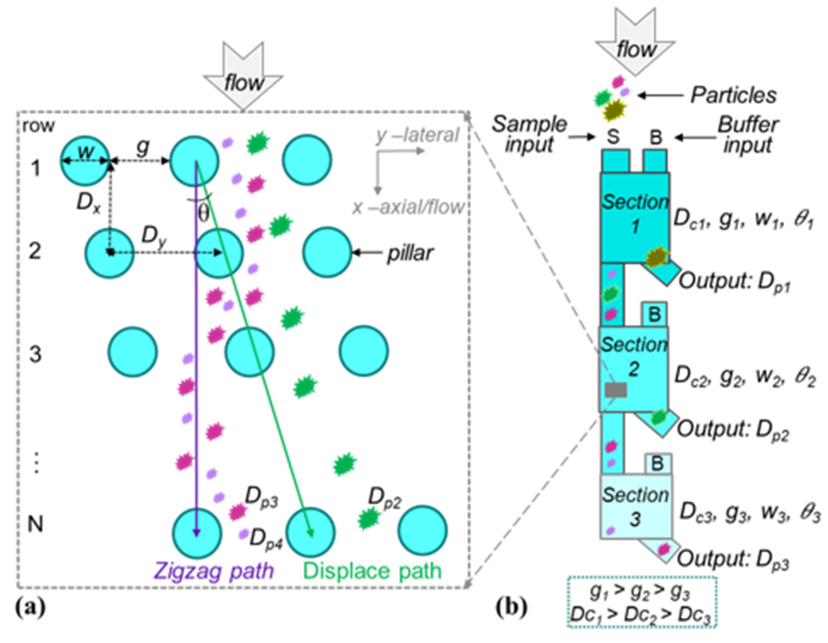
2. DLD Theory
3. Cascade Multi-Section DLD Separator
3.1. Externally Balanced Cascade Multi-Section DLD Approach
3.2. Fluidic Mechanisms and Design Rules for the Multi-Section Cascade DLD
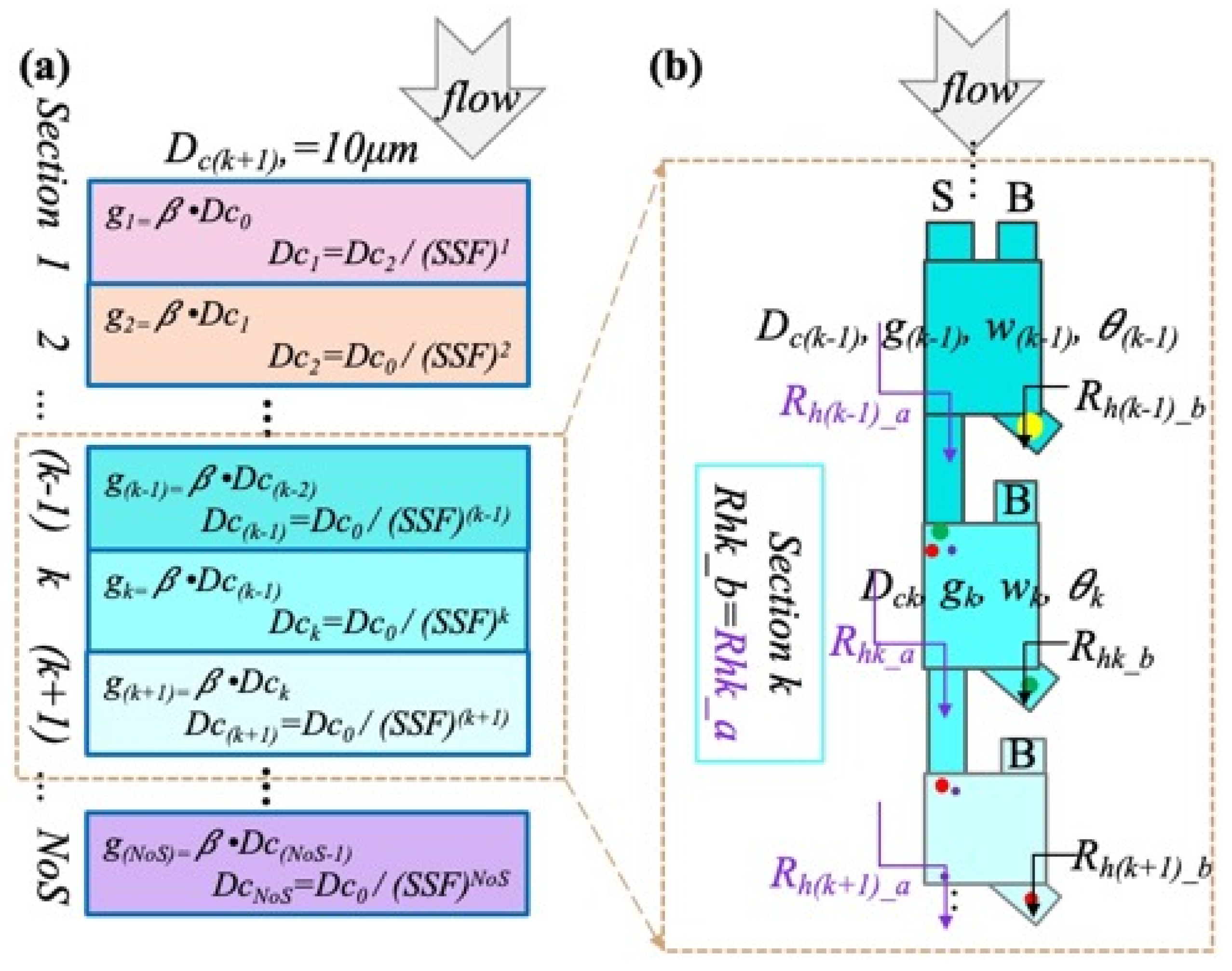
4. Multi-Section Mathematical Model
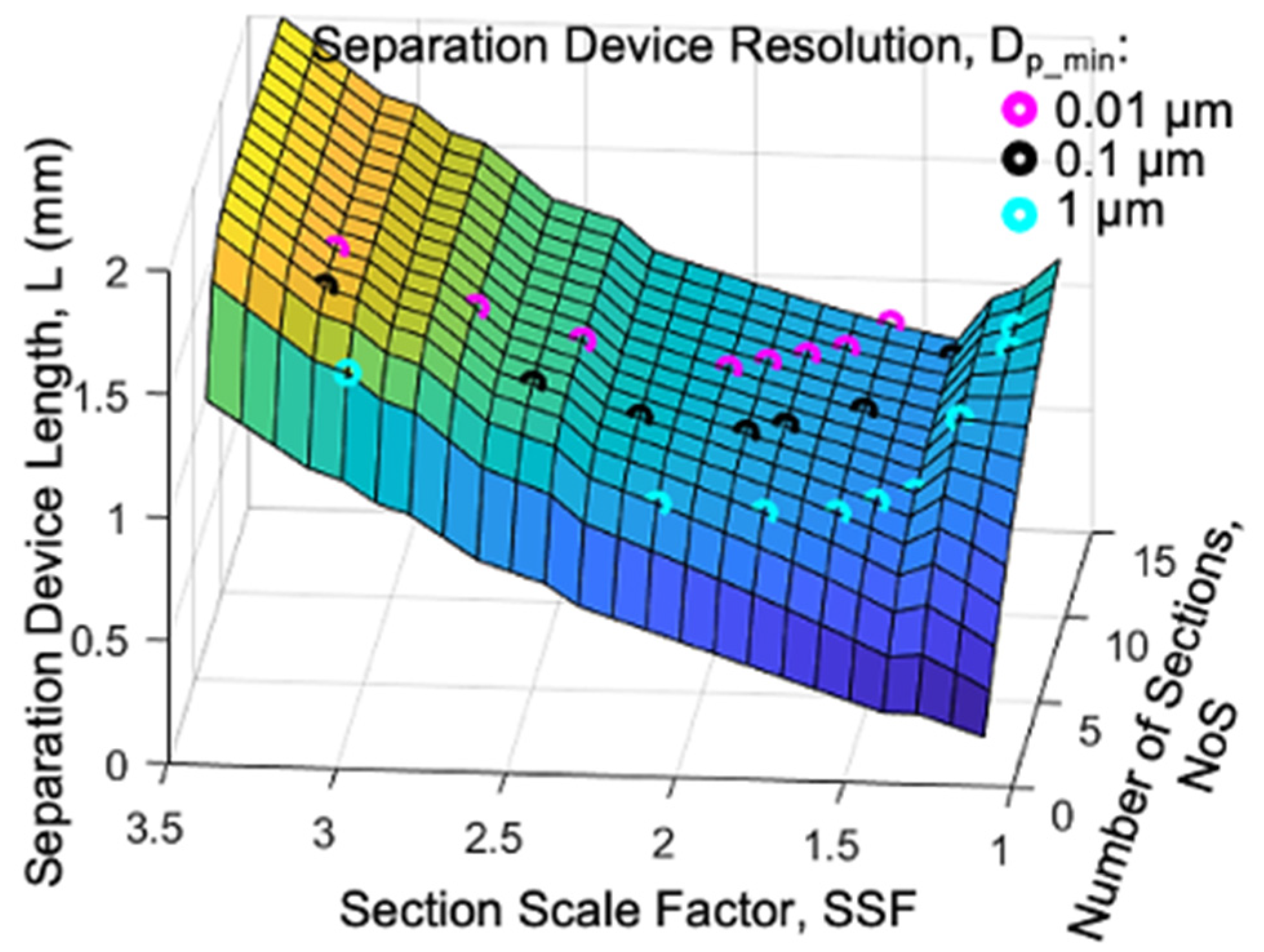
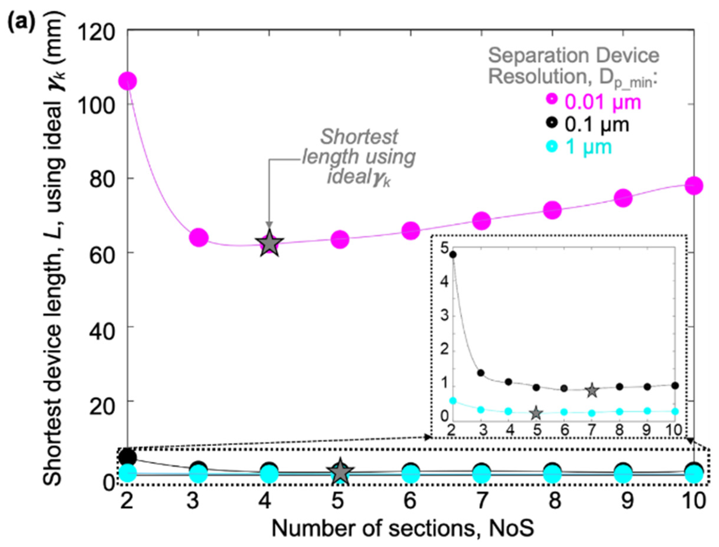
5. Preliminary Analysis to Define the Relationship between Design Parameters and Device Length
5.1. L vs. NoS Relationship for Different SSFs
5.2. L vs. SSF Relationship for Different NoS
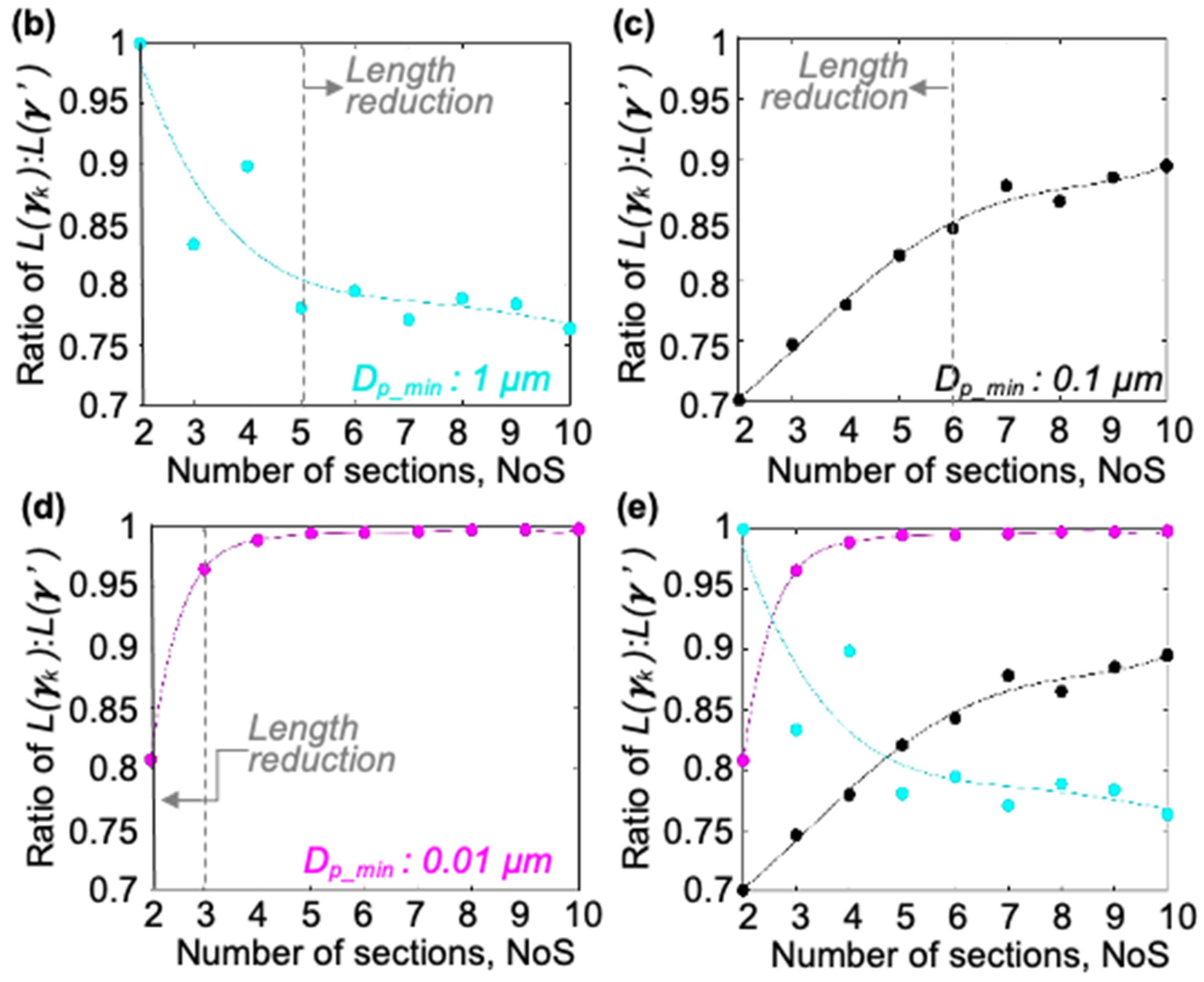
5.3. The Dp_min vs. NoS Relationship for Different SSFs
6. Analysis of Secondary Design Considerations
6.1. Fabrication Limit
6.2. Gamma Variation
6.3. I-Shaped Pillar (More Complex Pillar Geometry)
7. Case Study
7.1. Case 1
7.2. Case 2
7.3. Case 3
8. Conclusions
Supplementary Materials
Author Contributions
Funding
Data Availability Statement
Acknowledgments
Conflicts of Interest
References
- Mejía-Salazar, J.R.; Rodrigues Cruz, K.; Materon Vasques, E.M. Microfluidic Point-of-Care Devices: New Trends and Future Prospects for eHealth Diagnostics. Sensors 2020, 20, 1951. [Google Scholar] [CrossRef] [PubMed]
- Ardalan, S.; Hosseinifard, M.; Vosough, M.; Golmohammadi, H. Towards smart personalized perspiration analysis: An IoT-integrated cellulose-based microfluidic wearable patch for smartphone fluorimetric multi-sensing of sweat biomarkers. Biosens. Bioelectron. 2020, 168, 112450. [Google Scholar] [CrossRef] [PubMed]
- Blachowicz, T.; Ehrmann, A. 3D printed MEMS technology—Recent developments and applications. Micromachines 2020, 11, 434. [Google Scholar] [CrossRef] [PubMed]
- Dai, Q.; Bertleff-Zieschang, N.; Braunger, J.A.; Björnmalm, M.; Cortez-Jugo, C.; Caruso, F. Particle Targeting in Complex Biological Media. Adv. Heal. Mater. 2017, 7, 1700575. [Google Scholar] [CrossRef] [PubMed]
- Chikaura, H.; Nakashima, Y.; Fujiwara, Y.; Komohara, Y.; Takeya, M.; Nakanishi, Y. Effect of particle size on biological response by human monocyte-derived macrophages. Biosurface Biotribol. 2016, 2, 18–25. [Google Scholar] [CrossRef]
- Kim, K.-H.; Kabir, E.; Kabir, S. A review on the human health impact of airborne particulate matter. Environ. Int. 2015, 74, 136–143. [Google Scholar] [CrossRef]
- Chen, S.; Qiao, Z.; Niu, Y.; Yeo, J.C.; Liu, Y.; Qi, J.; Fan, S.; Liu, X.; Lee, J.Y.; Lim, C.T. Wearable flexible microfluidic sensing technologies. Nat. Rev. Bioeng. 2023, 1, 950–971. [Google Scholar] [CrossRef]
- Palekar, S.; Kalambe, J.; Patrikar, R.M. IoT enabled microfluidics-based biochemistry analyzer based on colorimetric detection techniques. Chem. Pap. 2023, 77, 2935–2945. [Google Scholar] [CrossRef]
- Pechlivani, E.M.; Papadimitriou, A.; Pemas, S.; Ntinas, G.; Tzovaras, D. IoT-Based Agro-Toolbox for Soil Analysis and Environmental Monitoring. Micromachines 2023, 14, 1698. [Google Scholar] [CrossRef]
- Blom, M.T.; Chmela, E.; Oosterbroek, R.E.; Tijssen, R.; Berg, A.v.D. On-Chip Hydrodynamic Chromatography Separation and Detection of Nanoparticles and Biomolecules. Anal. Chem. 2003, 75, 6761–6768. [Google Scholar] [CrossRef] [PubMed]
- Janča, J.; Berneron, J.-F.; Boutin, R. Micro-thermal field-flow fractionation: New high-performance method for particle size distribution analysis. J. Colloid Interface Sci. 2003, 260, 317–323. [Google Scholar] [CrossRef]
- Hartley, L.; Kaler, K.V.I.S.; Yadid-Pecht, O. Hybrid integration of an active pixel sensor and microfluidics for cytometry on a chip. IEEE Trans. Circuits Syst. I Regul. Pap. 2007, 54, 99–110. [Google Scholar] [CrossRef]
- Chakrabarty, K. Design Automation and Test Solutions for Digital Microfluidic Biochips. IEEE Trans. Circuits Syst. I Regul. Pap. 2009, 57, 4–17. [Google Scholar] [CrossRef]
- Antfolk, M.; Laurell, T. Continuous flow microfluidic separation and processing of rare cells and bioparticles found in blood—A review. Anal. Chim. Acta 2017, 965, 9–35. [Google Scholar] [CrossRef] [PubMed]
- Bhagat, A.A.S.; Bow, H.; Hou, H.W.; Tan, S.J.; Han, J.; Lim, C.T. Microfluidics for cell separation. Med. Biol. Eng. Comput. 2010, 48, 999–1014. [Google Scholar] [CrossRef]
- Doering, F.L.; Paprotny, I.; White, R.M. MEMS AirMicrofluidic Sensor for Portable Monitoring of Airborne Particulates. Sens. Actuators A Phys. 2013, 201, 505–516. [Google Scholar]
- Marple, V.A.; Olson, B.A. Sampling and Measurement Using Inertial, Gravitational, Centrifugal, and Thermal Techniques. In Aerosol Measurement: Principles, Techniques, and Applications; John Wiley & Sons, Inc.: Hoboken, NJ, USA, 2011. [Google Scholar]
- Yin, H.; Wan, H.; Mason, A.J. Separation and Electrochemical Detection Platform for Portable Individual PM2.5 Monitoring. In Proceedings of the IEEE International Symposium on Circuits and Systems, Baltimore, MD, USA, 28–31 May 2017. [Google Scholar]
- Poenar, D.P. Microfluidic and micromachined/MEMS devices for separation, discrimination and detection of airborne particles for pollution monitoring. Micromachines 2019, 10, 483. [Google Scholar] [CrossRef] [PubMed]
- McGrath, J.; Jimenez, M.; Bridle, H. Deterministic lateral displacement for particle separation: A review. Lab A Chip 2014, 14, 4139–4158. [Google Scholar] [CrossRef]
- Zeming, K.K.; Ranjan, S.; Zhang, Y. Rotational separation of non-spherical bioparticles using I-shaped pillar arrays in a microfluidic device. Nat. Commun. 2013, 4, 1625. [Google Scholar] [CrossRef]
- Ranjan, S.; Zeming, K.K.; Jureen, R.; Fisher, D.; Zhang, Y. DLD pillar shape design for efficient separation of spherical and non-spherical bioparticles. Lab A Chip 2014, 14, 4250–4262. [Google Scholar] [CrossRef]
- Wunsch, B.H.; Smith, J.T.; Gifford, S.M.; Wang, C.; Brink, M.; Bruce, R.L.; Austin, R.H.; Stolovitzky, G.; Astier, Y. Nanoscale lateral displacement arrays for the separation of exosomes and colloids down to 20 nm. Nat. Nanotechnol. 2016, 11, 936–940. [Google Scholar] [CrossRef] [PubMed]
- Pariset, E.; Pudda, C.; Boizot, F.; Verplanck, N.; Revol-Cavalier, F.; Berthier, J.; Thuaire, A.; Agache, V. Purification of complex samples: Implementation of a modular and reconfigurable droplet-based microfluidic platform with cascaded deterministic lateral displacement separation modules. PLoS ONE 2018, 13, e0197629. [Google Scholar] [CrossRef] [PubMed]
- Tottori, N.; Hatsuzawa, T.; Nisisako, T. Separation of main and satellite droplets in a deterministic lateral displacement microfluidic device. RSC Adv. 2017, 7, 35516–35524. [Google Scholar] [CrossRef]
- Yin, H.; Dávila-Montero, S.; Mason, A.J. Analysis of Section Scaling for Multiple-Size DLD Microfluidic Particle Separation. In Proceedings of the ISCAS 2020 IEEE International Symposium on Circuits and Systems, Sevilla, Spain, 10–21 October 2020; pp. 1–5. [Google Scholar] [CrossRef]
- Davis, J.A.; Inglis, D.W.; Morton, K.J.; Lawrence, D.A.; Huang, L.R.; Chou, S.Y.; Sturm, J.C.; Austin, R.H. Deterministic hydrodynamics: Taking blood apart. Proc. Natl. Acad. Sci. USA 2006, 103, 14779–14784. [Google Scholar] [CrossRef] [PubMed]
- Karabacak, N.M.; Spuhler, P.S.; Fachin, F.; Lim, E.J.; Pai, V.; Ozkumur, E.; Martel, J.M.; Kojic, N.; Smith, K.; Chen, P.-I.; et al. Microfluidic, marker-free isolation of circulating tumor cells from blood samples. Nat. Protoc. 2014, 9, 694–710. [Google Scholar] [CrossRef] [PubMed]
- Holmes, D.; Whyte, G.; Bailey, J.; Vergara-Irigaray, N.; Ekpenyong, A.; Guck, J.; Duke, T.; David, H.; Graeme, W.; Joe, B.; et al. Separation of blood cells with differing deformability using deterministic lateral displacement. Interface Focus 2014, 4, 20140011. [Google Scholar] [CrossRef]
- Inglis, D.W.; Morton, K.J.; Davis, J.A.; Zieziulewicz, T.J.; Lawrence, D.A.; Austin, R.H.; Sturm, J.C. Microfluidic device for label-free measurement of platelet activation. Lab A Chip 2008, 8, 925–931. [Google Scholar] [CrossRef]
- Holm, S.H.; Beech, J.P.; Barrett, M.P.; Tegenfeldt, J.O.; Holm, S.H.; Beech, J.P.; Barrett, M.P.; Tegenfeldt, J.O. Separation of parasites from human blood using deterministic lateral displacement. Lab A Chip 2011, 11, 1326–1332. [Google Scholar] [CrossRef]
- Zeming, K.K.; Thakor, N.V.; Zhang, Y.; Chen, C.-H. Real-time modulated nanoparticle separation with an ultra-large dynamic range. Lab A Chip 2015, 16, 75–85. [Google Scholar] [CrossRef]
- Laki, A.J.; Botzheim, L.; Iván, K.; Tamási, V.; Civera, P. Separation of Microvesicles from Serological Samples Using Deterministic Lateral Displacement Effect. BioNanoScience 2014, 5, 48–54. [Google Scholar] [CrossRef]
- Au, S.H.; Edd, J.; Stoddard, A.E.; Wong, K.H.K.; Fachin, F.; Maheswaran, S.; Haber, D.A.; Stott, S.L.; Kapur, R.; Toner, M. Microfluidic isolation of circulating tumor cell clusters by size and asymmetry. Sci. Rep. 2017, 7, 2433. [Google Scholar] [CrossRef] [PubMed]
- Hochstetter, A.; Vernekar, R.; Austin, R.H.; Becker, H.; Beech, J.P.; Fedosov, D.A.; Gompper, G.; Kim, S.-C.; Smith, J.T.; Stolovitzky, G.; et al. Deterministic Lateral Displacement: Challenges and Perspectives. ACS Nano 2020, 14, 10784–10795. [Google Scholar] [CrossRef] [PubMed]
- Inglis, D.W.; Davis, J.A.; Austin, R.H.; Sturm, J.C. Critical particle size for fractionation by deterministic lateral displacement. Lab A Chip 2006, 6, 655–658. [Google Scholar] [CrossRef] [PubMed]
- Yeom, J.; Agonafer, D.D.; Han, J.-H.; A Shannon, M. Low Reynolds number flow across an array of cylindrical microposts in a microchannel and figure-of-merit analysis of micropost-filled microreactors. J. Micromechanics Microengineering 2009, 19, 065025. [Google Scholar] [CrossRef]
- Vernekar, R.; Krüger, T.; Loutherback, K.; Morton, K.; Inglis, D.W. Anisotropic permeability in deterministic lateral displacement arrays. Lab A Chip 2017, 17, 3318–3330. [Google Scholar] [CrossRef] [PubMed]
- Inglis, D.; Vernekar, R.; Krüger, T.; Feng, S. The fluidic resistance of an array of obstacles and a method for improving boundaries in deterministic lateral displacement arrays. Microfluid. Nanofluidics 2020, 24, 18. [Google Scholar] [CrossRef]
- Zeming, K.K.; Salafi, T.; Chen, C.-H.; Zhang, Y. Asymmetrical Deterministic Lateral Displacement Gaps for Dual Functions of Enhanced Separation and Throughput of Red Blood Cells. Sci. Rep. 2016, 6, 22934. [Google Scholar] [CrossRef]
- Kim, S.-C.; Wunsch, B.H.; Hu, H.; Smith, J.T.; Austin, R.H.; Stolovitzky, G. Broken flow symmetry explains the dynamics of small particles in deterministic lateral displacement arrays. Proc. Natl. Acad. Sci. USA 2017, 114, E5034–E5041. [Google Scholar] [CrossRef]
- Loutherback, K.; Chou, K.S.; Newman, J.; Puchalla, J.; Austin, R.H.; Sturm, J.C. Improved performance of deterministic lateral displacement arrays with triangular posts. Microfluid. Nanofluidics 2010, 9, 1143–1149. [Google Scholar] [CrossRef]


| Variables | Definition |
|---|---|
| Dck | Critical diameter of the particle |
| Dp_max | Biggest particle that will be separated |
| Dp_min | Smallest particle that will be separated |
| w | Diameter of the pillar |
| g | Gap between the pillar (in the lateral direction) |
| Dx | Center-to-center distance in the flow direction |
| Dy | Center-to-center distance in the lateral direction |
| L | Total length of the device |
| NoS | Number of sections |
| SSF | Section-scaling factor |
| N | Number of rows required for one column shift |
| γ | Pillar diameter to gap ratio (γ = w/g) |
| β | 1.1—design tolerance |
| θ | Gradient angle (tan(θ) = 1/N) |
| m | 1 (Number of columns to be displaced) |
| Cases | DLD Device Length | |
|---|---|---|
| Case 1: I-shaped pillar; 6 µm; | Dp_min = 0.01 µm; Dp_max = 10 µm | L = 60 m Dynamic range = 1000 |
| Case 2: Circle-shaped pillar; = 0.1 µm; | Dp_min = 1 µm; Dp_max = 10 µm; | L ~ 0.3 mm Dynamic range = 10 |
| Dp_min = 0.01 µm; Dp_max = 10 µm; | L ~ 41 mm Dynamic range = 1000 | |
| Case 3: Circle-shaped pillar; = 10 µm; | Dp_min = 1 µm; Dp_max = 100 µm; | L ~ 8 mm Dynamic range = 100 |
Disclaimer/Publisher’s Note: The statements, opinions and data contained in all publications are solely those of the individual author(s) and contributor(s) and not of MDPI and/or the editor(s). MDPI and/or the editor(s) disclaim responsibility for any injury to people or property resulting from any ideas, methods, instructions or products referred to in the content. |
© 2024 by the authors. Licensee MDPI, Basel, Switzerland. This article is an open access article distributed under the terms and conditions of the Creative Commons Attribution (CC BY) license (https://creativecommons.org/licenses/by/4.0/).
Share and Cite
Yin, H.; Dávila-Montero, S.; Mason, A.J. Geometry Scaling for Externally Balanced Cascade Deterministic Lateral Displacement Microfluidic Separation of Multi-Size Particles. Micromachines 2024, 15, 405. https://doi.org/10.3390/mi15030405
Yin H, Dávila-Montero S, Mason AJ. Geometry Scaling for Externally Balanced Cascade Deterministic Lateral Displacement Microfluidic Separation of Multi-Size Particles. Micromachines. 2024; 15(3):405. https://doi.org/10.3390/mi15030405
Chicago/Turabian StyleYin, Heyu, Sylmarie Dávila-Montero, and Andrew J. Mason. 2024. "Geometry Scaling for Externally Balanced Cascade Deterministic Lateral Displacement Microfluidic Separation of Multi-Size Particles" Micromachines 15, no. 3: 405. https://doi.org/10.3390/mi15030405