Ultraflexible PEDOT:PSS/IrOx-Modified Electrodes: Applications in Behavioral Modulation and Neural Signal Recording in Mice

 ,
, 
Abstract
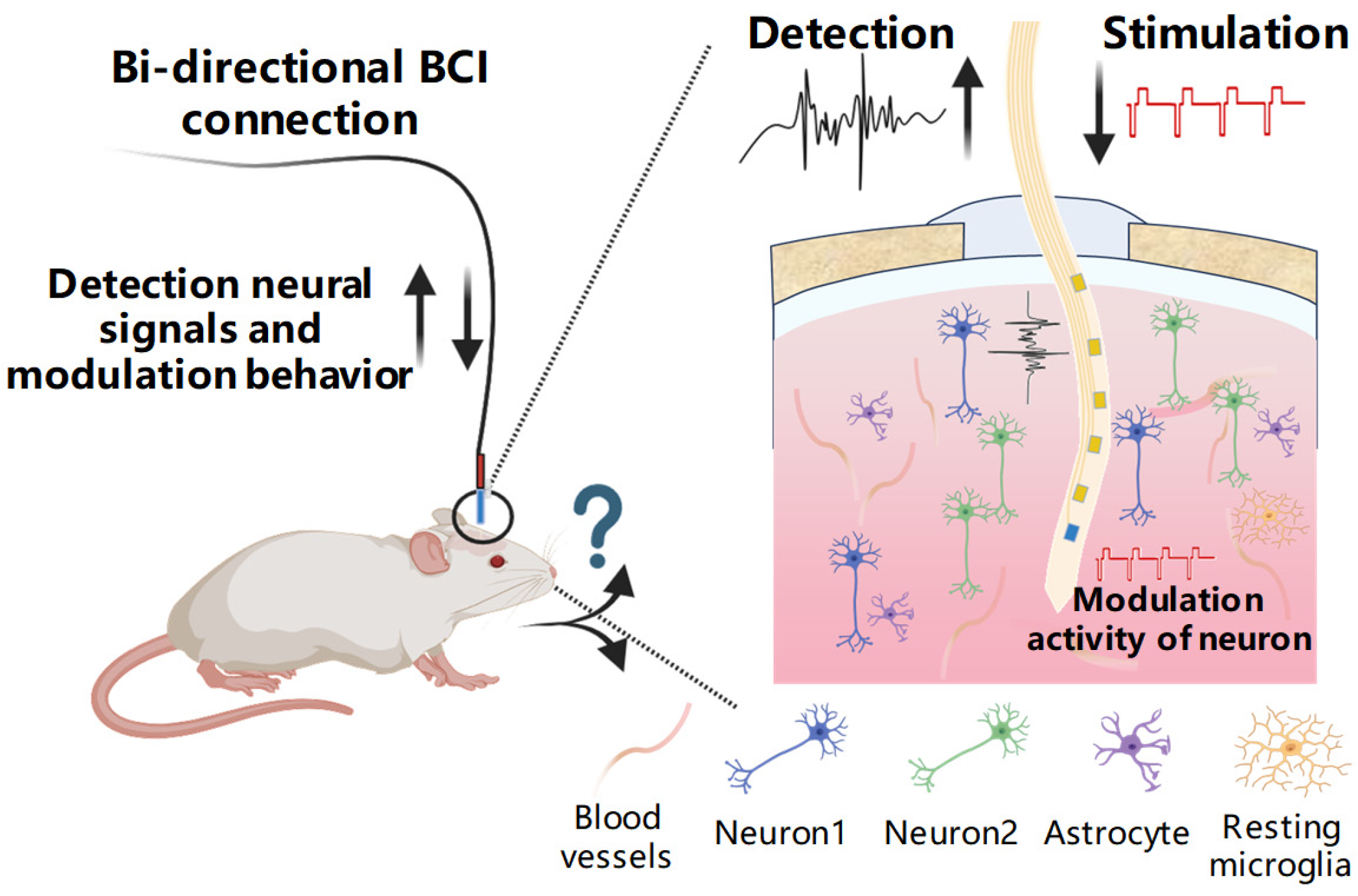
1. Introduction
2. Materials and Methods
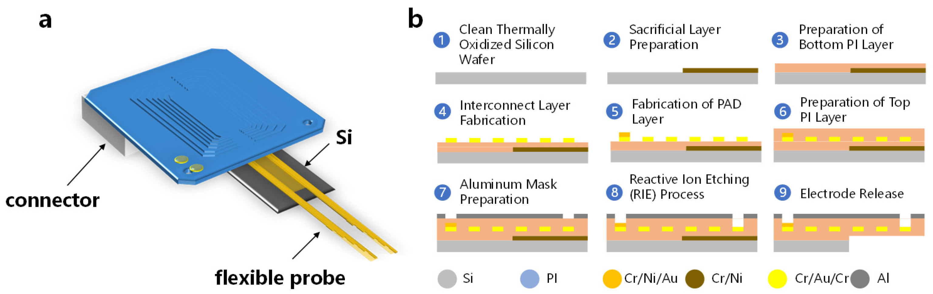
2.1. Fabrication and Packaging of a Flexible Probe
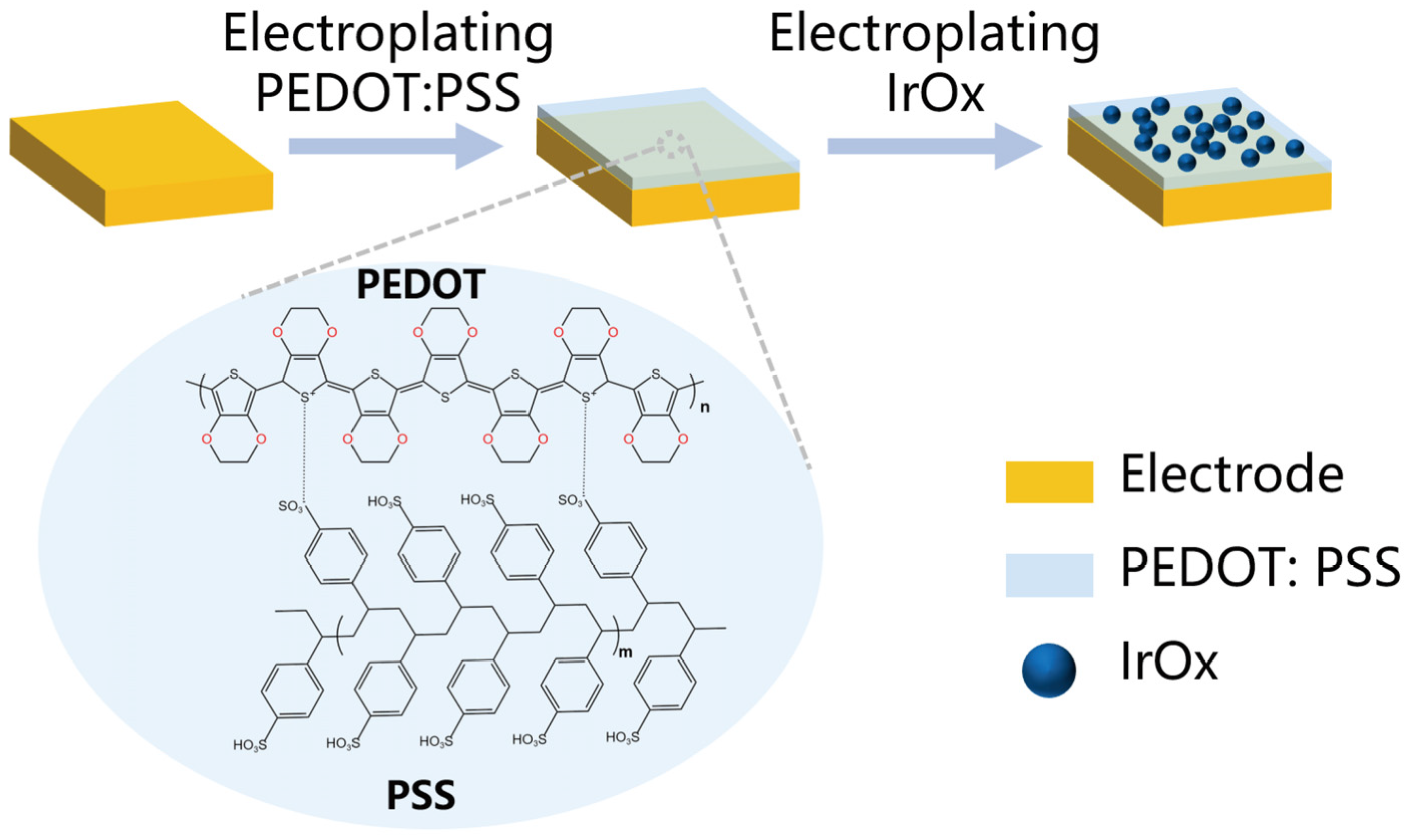
2.2. The Modification Methods of Electrode
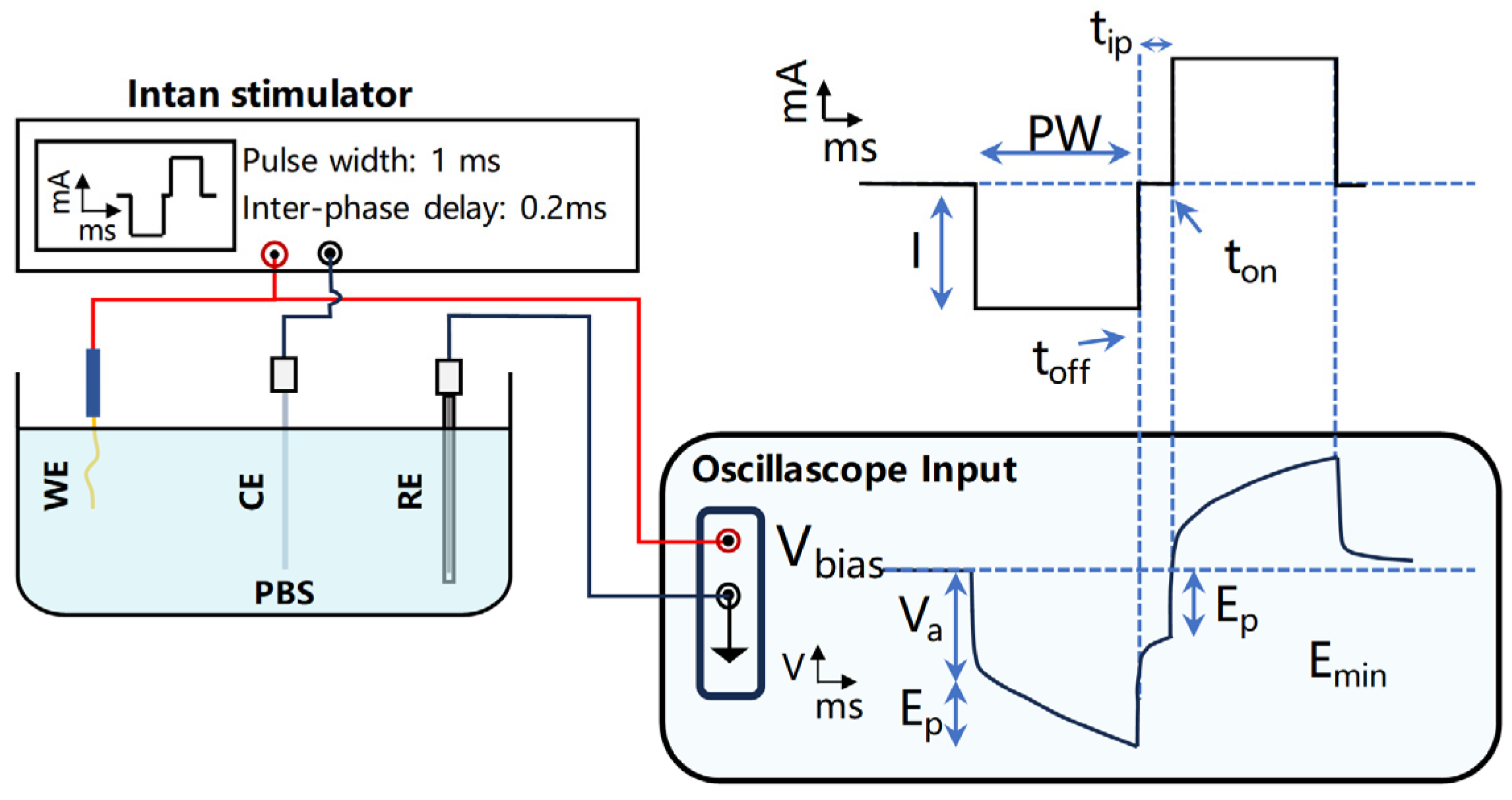
2.3. The Impedance and Stimulation Performance Test Methods of Electrode
2.4. Electrical Recording and Analysis of Neural Activity
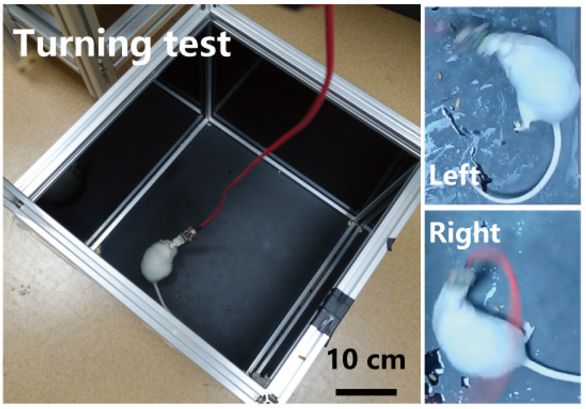
2.5. Behavioral Modulation and Analysis in Mice
3. Results and Discussion
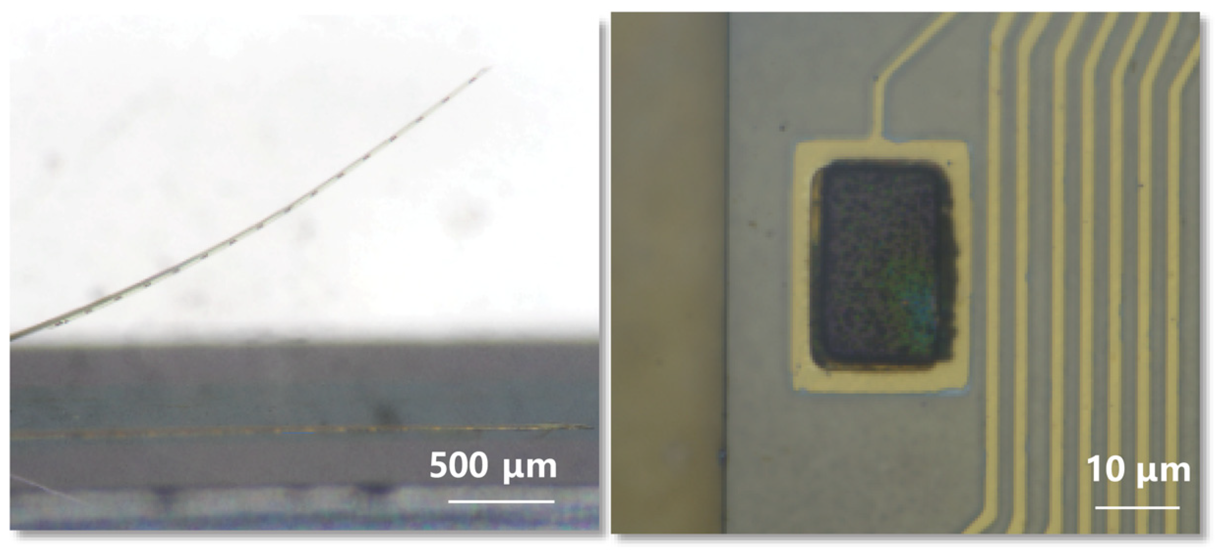
3.1. The Design and Morphology of a Flexible Probe
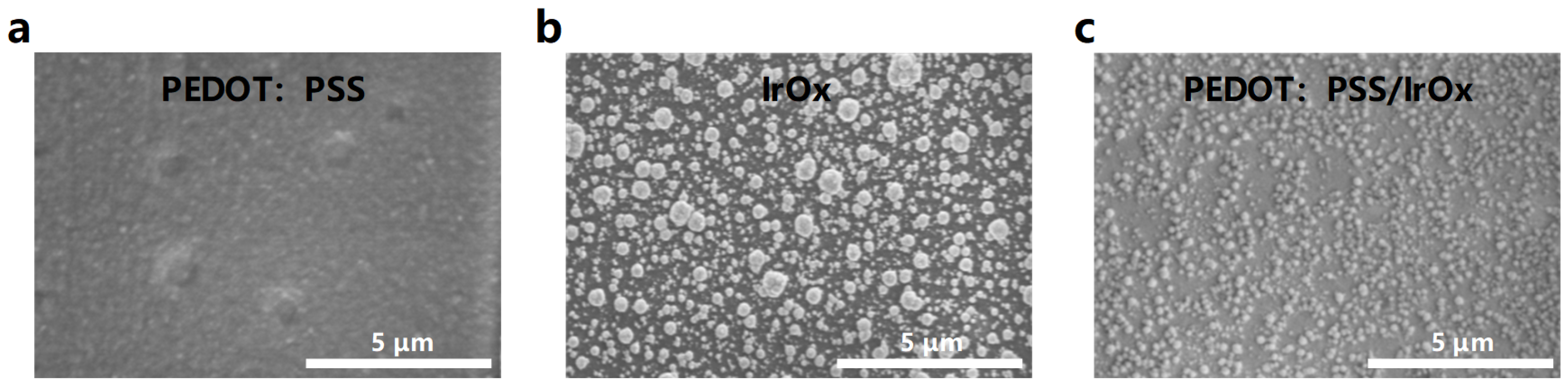
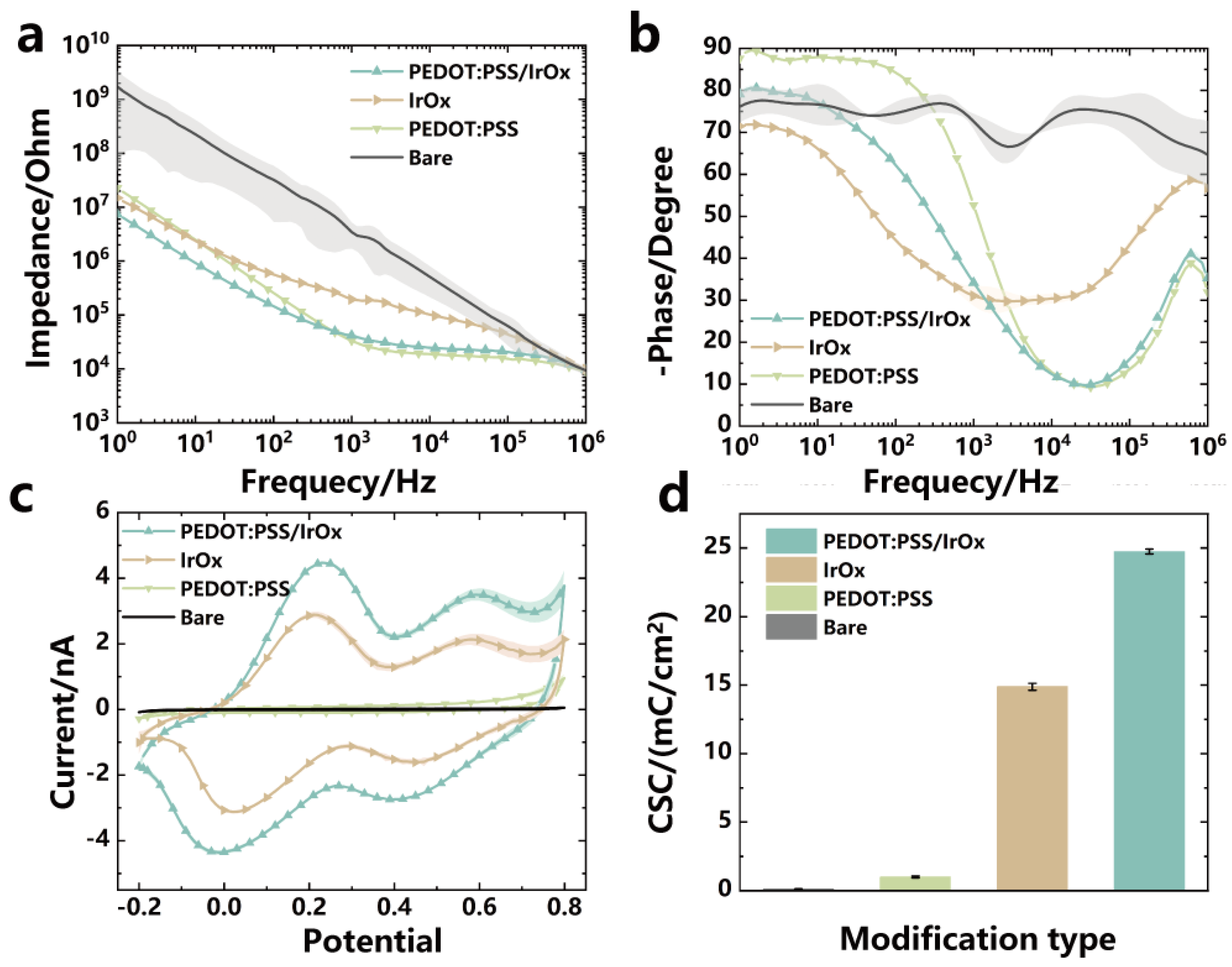
3.2. SEM and Electrochemical Properties of Modified Electrodes
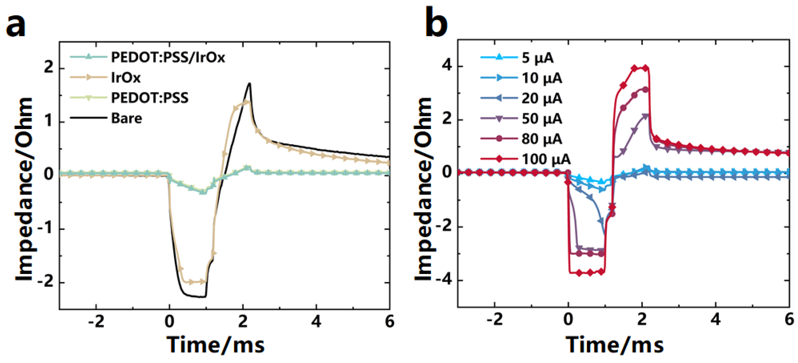
3.3. The Charge Transfer Properties of the Modified Electrodes
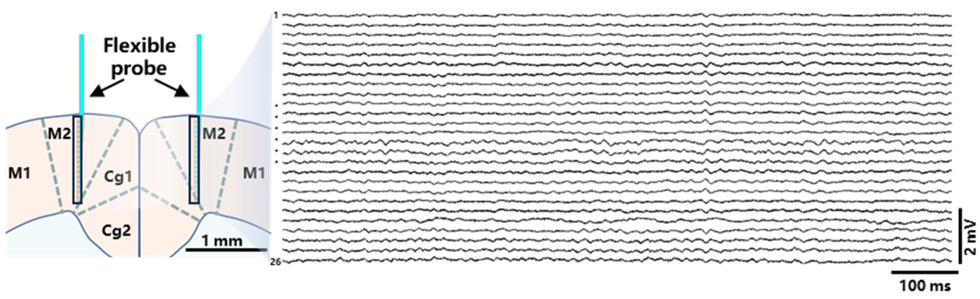
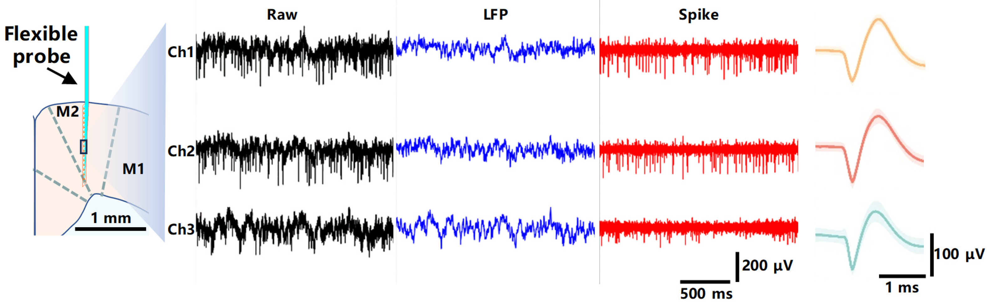
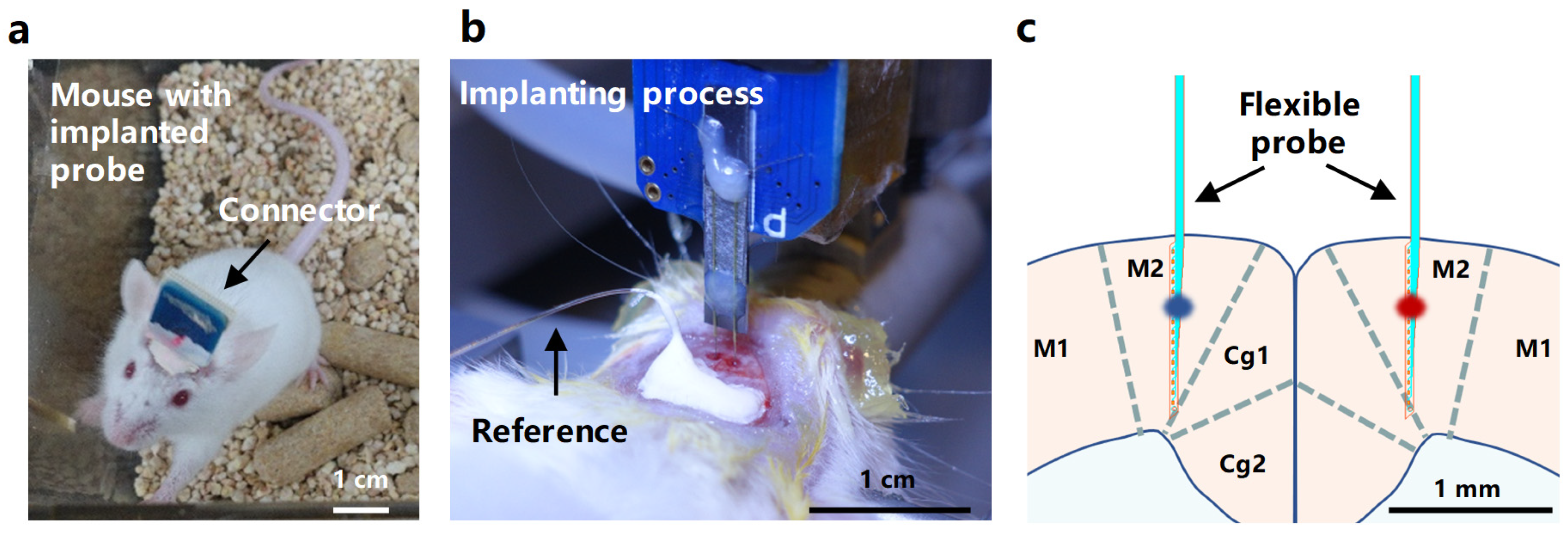
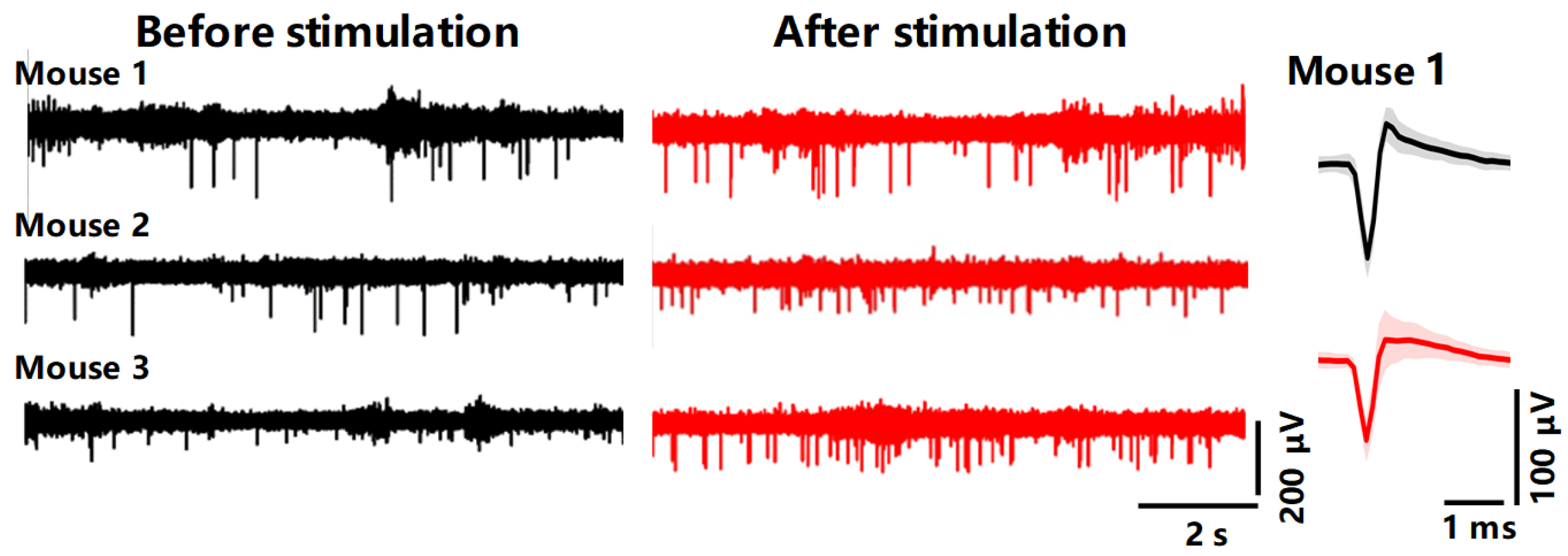
3.4. In Vivo Recording of Neural Electrical Signals by the Implanted Probe
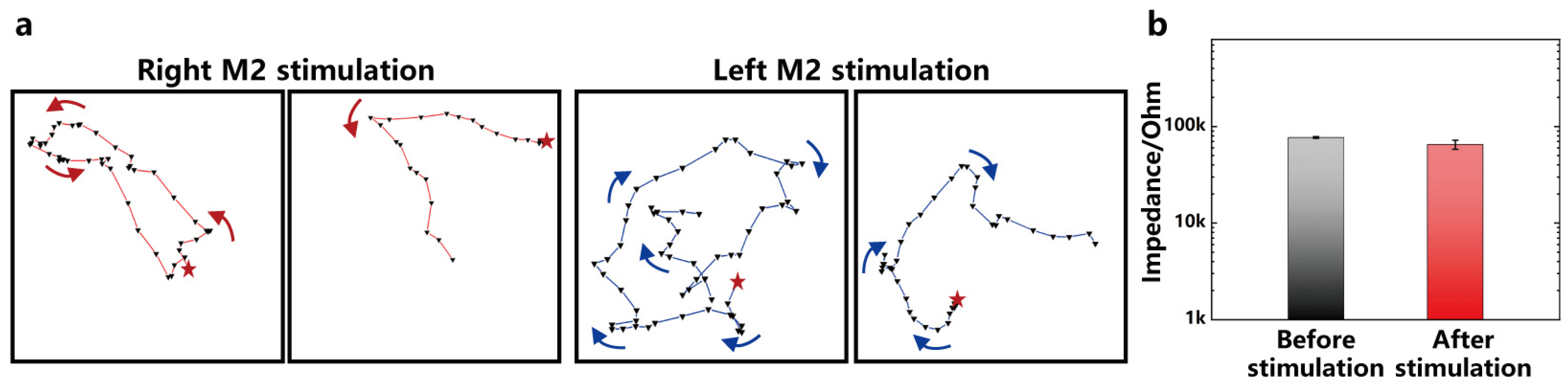
3.5. Electrical Stimulation Modulates Mice Behavior
4. Conclusions
Author Contributions
Funding
Data Availability Statement
Conflicts of Interest
Appendix A
References
- Cramb, K.M.L.; Beccano-Kelly, D.; Cragg, S.J.; Wade-Martins, R. Impaired Dopamine Release in Parkinson’s Disease. Brain J. Neurol. 2023, 146, 3117–3132. [Google Scholar] [CrossRef] [PubMed]
- Davis, S.E.; Cirincione, A.B.; Jimenez-Torres, A.C.; Zhu, J. The Impact of Neurotransmitters on the Neurobiology of Neurodegenerative Diseases. Int. J. Mol. Sci. 2023, 24, 15340. [Google Scholar] [CrossRef] [PubMed]
- Xu, M.; Zhao, Y.; Xu, G.; Zhang, Y.; Sun, S.; Sun, Y.; Wang, J.; Pei, R. Recent Development of Neural Microelectrodes with Dual-Mode Detection. Biosensors 2023, 13, 59. [Google Scholar] [CrossRef] [PubMed]
- Lycke, R.; Kim, R.; Zolotavin, P.; Montes, J.; Sun, Y.; Koszeghy, A.; Altun, E.; Noble, B.; Yin, R.; He, F.; et al. Low-Threshold, High-Resolution, Chronically Stable Intracortical Microstimulation by Ultraflexible Electrodes. Cell Rep. 2023, 42, 112554. [Google Scholar] [CrossRef] [PubMed]
- Biran, R.; Martin, D.C.; Tresco, P.A. Neuronal Cell Loss Accompanies the Brain Tissue Response to Chronically Implanted Silicon Microelectrode Arrays. Exp. Neurol. 2005, 195, 115–126. [Google Scholar] [CrossRef] [PubMed]
- Roitbak, T.; Sykova, E. Diffusion Barriers Evoked in the Rat Cortex by Reactive Astrogliosis. Glia 1999, 28, 40–48. [Google Scholar] [CrossRef]
- Wang, Y.; Yang, X.; Zhang, X.; Wang, Y.; Pei, W. Implantable Intracortical Microelectrodes: Reviewing the Present with a Focus on the Future. Microsyst. Nanoeng. 2023, 9, 7. [Google Scholar] [CrossRef]
- Zhang, T.; Chai, Y.; Wang, S.; Yu, J.; Jiang, S.; Zhu, W.; Fang, Z.; Li, B. Recent Study Advances in Flexible Sensors Based on Polyimides. Sensors 2023, 23, 9743. [Google Scholar] [CrossRef]
- Wei, X.; Luan, L.; Zhao, Z.; Li, X.; Zhu, H.; Potnis, O.; Xie, C. Nanofabricated Ultraflexible Electrode Arrays for High-Density Intracortical Recording. Adv. Sci. 2018, 5, 1700625. [Google Scholar] [CrossRef]
- Luan, L.; Wei, X.; Zhao, Z.; Siegel, J.J.; Potnis, O.; Tuppen, C.A.; Lin, S.; Kazmi, S.; Fowler, R.A.; Holloway, S.; et al. Ultraflexible Nanoelectronic Probes Form Reliable, Glial Scar-Free Neural Integration. Sci. Adv. 2017, 3, e1601966. [Google Scholar] [CrossRef]
- He, F.; Lycke, R.; Ganji, M.; Xie, C.; Luan, L. Ultraflexible Neural Electrodes for Long-Lasting Intracortical Recording. iScience 2020, 23, 101387. [Google Scholar] [CrossRef] [PubMed]
- Guo, Z.; Wang, F.; Wang, L.; Tu, K.; Jiang, C.; Xi, Y.; Hong, W.; Xu, Q.; Wang, X.; Yang, B.; et al. A Flexible Neural Implant with Ultrathin Substrate for Low-Invasive Brain–Computer Interface Applications. Microsyst. Nanoeng. 2022, 8, 133. [Google Scholar] [CrossRef] [PubMed]
- Seo, K.J.; Artoni, P.; Qiang, Y.; Zhong, Y.; Han, X.; Shi, Z.; Yao, W.; Fagiolini, M.; Fang, H. Transparent, Flexible, Penetrating Microelectrode Arrays with Capabilities of Single-Unit Electrophysiology. Adv. Biosyst. 2019, 3, 1800276. [Google Scholar] [CrossRef] [PubMed]
- Ji, B.; Wang, M.; Ge, C.; Xie, Z.; Guo, Z.; Hong, W.; Gu, X.; Wang, L.; Yi, Z.; Jiang, C.; et al. Flexible Bioelectrodes with Enhanced Wrinkle Microstructures for Reliable Electrochemical Modification and Neuromodulation in Vivo. Biosens. Bioelectron. 2019, 135, 181–191. [Google Scholar] [CrossRef] [PubMed]
- Fan, X.; Nie, W.; Tsai, H.; Wang, N.; Huang, H.; Cheng, Y.; Wen, R.; Ma, L.; Yan, F.; Xia, Y. PEDOT:PSS for Flexible and Stretchable Electronics: Modifications, Strategies, and Applications. Adv. Sci. 2019, 6, 1900813. [Google Scholar] [CrossRef] [PubMed]
- Nasser, R.A.; Arya, S.S.; Alshehhi, K.H.; Teo, J.C.M.; Pitsalidis, C. Conducting Polymer Scaffolds: A New Frontier in Bioelectronics and Bioengineering. Trends Biotechnol. 2024. [Google Scholar] [CrossRef]
- Anmona, S.; Andreas, S.; André, B.; Walter, L. PEDOT: PSS Coating on Gold Microelectrodes with Excellent Stability and High Charge Injection Capacity for Chronic Neural Interfaces. Sens. Actuators B Chem. 2018, 275, 382–393. [Google Scholar]
- Liangqi, O.; Bin, W.; Chin-chen, K.; Sheevangi, P.; Brendan, F.; David, C. Enhanced PEDOT Adhesion on Solid Substrates with Electrografted P(EDOT-NH2). Adv. Sci. 2017, 3, 1600448. [Google Scholar]
- Kang, X.; Liu, J.; Tian, H.; Yang, B.; NuLi, Y.; Yang, C. Sputtered Iridium Oxide Modified Flexible Parylene Microelectrodes Array for Electrical Recording and Stimulation of Muscles. Sens. Actuators B Chem. 2016, 225, 267–278. [Google Scholar] [CrossRef]
- Schiavone, G.; Wagner, F.B.; Fallegger, F.; Kang, X.; Vachicouras, N.; Barra, B.; Capogrosso, M.; Bloch, J.; Courtine, G.; Lacour, S.P. Long-Term Functionality of a Soft Electrode Array for Epidural Spinal Cord Stimulation in a Minipig Model. In Proceedings of the 2018 40th Annual International Conference of the IEEE Engineering in Medicine and Biology Society (EMBC), Honolulu, HI, USA, 18–21 July 2018; pp. 1432–1435. [Google Scholar]
- Schiavone, G.; Fallegger, F.; Schönle, P.; Huang, Q.; Lacour, S.P. Microfabricated Bioelectronic Systems for Prevention, Diagnostics and Treatment of Neurological Disorders. In Proceedings of the 2019 IEEE International Electron Devices Meeting (IEDM), San Francisco, CA, USA, 7–11 December 2019; pp. 10.2.1–10.2.4. [Google Scholar]
- Ye, Y.; Wang, Z.; Tian, Y.; Zhou, T.; Zhou, Z.; Wei, X.; Tao, T.H.; Sun, L. A Brain-to-Brain Interface with a Flexible Neural Probe for Mouse Turning Control by Human Mind. IEEJ Trans. Electr. Electron. Eng. 2024. early view. [Google Scholar]
- Ye, Y.; Tian, Y.; Wang, H.; Cheng, Q.; Zhang, K.; Wang, X.; Zhou, C.; Xu, C.; Wei, X.; Zhou, Z.; et al. Flexible Bi-Directional Brain Computer Interface for Controlling Turning Behavior of Mice. In Proceedings of the 2023 IEEE 36th International Conference on Micro Electro Mechanical Systems (MEMS), Munich, Germany, 15–19 January 2023; pp. 33–36. [Google Scholar]
- Weltin, A.; Kieninger, J. Electrochemical Methods for Neural Interface Electrodes. J. Neural Eng. 2021, 18, 052001. [Google Scholar] [CrossRef]
- Huigen, E.; Peper, A.; Grimbergen, C.A. Investigation into the Origin of the Noise of Surface Electrodes. Med. Biol. Eng. Comput. 2002, 40, 332–338. [Google Scholar] [CrossRef]
- Lewis, C.M.; Boehler, C.; Liljemalm, R.; Fries, P.; Stieglitz, T.; Asplund, M. Recording Quality Is Systematically Related to Electrode Impedance. Adv. Healthc. Mater. 2024, 2303401. [Google Scholar] [CrossRef]
- Neto, J.P.; Baião, P.; Lopes, G.; Frazão, J.; Nogueira, J.; Fortunato, E.; Barquinha, P.; Kampff, A.R. Does Impedance Matter When Recording Spikes With Polytrodes? Front. Neurosci. 2018, 12, 408156. [Google Scholar] [CrossRef]
- Cogan, S.F.; Ludwig, K.A.; Welle, C.G.; Takmakov, P.A. Tissue Damage Thresholds during Therapeutic Electrical Stimulation. J. Neural Eng. 2016, 13, 021001. [Google Scholar] [CrossRef] [PubMed]


Disclaimer/Publisher’s Note: The statements, opinions and data contained in all publications are solely those of the individual author(s) and contributor(s) and not of MDPI and/or the editor(s). MDPI and/or the editor(s) disclaim responsibility for any injury to people or property resulting from any ideas, methods, instructions or products referred to in the content. |
© 2024 by the authors. Licensee MDPI, Basel, Switzerland. This article is an open access article distributed under the terms and conditions of the Creative Commons Attribution (CC BY) license (https://creativecommons.org/licenses/by/4.0/).
Share and Cite
Wang, X.; Jiang, W.; Yang, H.; Ye, Y.; Zhou, Z.; Sun, L.; Nie, Y.; Tao, T.H.; Wei, X. Ultraflexible PEDOT:PSS/IrOx-Modified Electrodes: Applications in Behavioral Modulation and Neural Signal Recording in Mice. Micromachines 2024, 15, 447. https://doi.org/10.3390/mi15040447
Wang X, Jiang W, Yang H, Ye Y, Zhou Z, Sun L, Nie Y, Tao TH, Wei X. Ultraflexible PEDOT:PSS/IrOx-Modified Electrodes: Applications in Behavioral Modulation and Neural Signal Recording in Mice. Micromachines. 2024; 15(4):447. https://doi.org/10.3390/mi15040447
Chicago/Turabian StyleWang, Xueying, Wanqi Jiang, Huiran Yang, Yifei Ye, Zhitao Zhou, Liuyang Sun, Yanyan Nie, Tiger H. Tao, and Xiaoling Wei. 2024. "Ultraflexible PEDOT:PSS/IrOx-Modified Electrodes: Applications in Behavioral Modulation and Neural Signal Recording in Mice" Micromachines 15, no. 4: 447. https://doi.org/10.3390/mi15040447
APA StyleWang, X., Jiang, W., Yang, H., Ye, Y., Zhou, Z., Sun, L., Nie, Y., Tao, T. H., & Wei, X. (2024). Ultraflexible PEDOT:PSS/IrOx-Modified Electrodes: Applications in Behavioral Modulation and Neural Signal Recording in Mice. Micromachines, 15(4), 447. https://doi.org/10.3390/mi15040447