Article

High-Speed Generation of Microbubbles with Constant Cumulative Production in a Glass Capillary Microfluidic Bubble Generator

1
Key Laboratory of Measuring & Online Assessment of Energy for Jiangsu Province Market Regulation, Suzhou Institute of Metrology, Suzhou 215128, China
2
Zhejiang Provincial Key Laboratory of Flow Measurement Technology, China Jiliang University, Hangzhou 310018, China
3
Dalian Institute of Metrology Inspection and Testing Co., Ltd., Dalian 116000, China
4
School of Mechatronics Engineering, Harbin Institute of Technology, Harbin 150001, China
*
Author to whom correspondence should be addressed.
Micromachines 2024, 15(6), 752; https://doi.org/10.3390/mi15060752
Submission received: 17 April 2024 / Revised: 29 May 2024 / Accepted: 31 May 2024 / Published: 2 June 2024
(This article belongs to the Special Issue Recent Development of Micro/Nanofluidic Devices)

Abstract

:
This work reports a simple bubble generator for the high-speed generation of microbubbles with constant cumulative production. To achieve this, a gas–liquid co-flowing microfluidic device with a tiny capillary orifice as small as 5 μm is fabricated to produce monodisperse microbubbles. The diameter of the microbubbles can be adjusted precisely by tuning the input gas pressure and flow rate of the continuous liquid phase. The co-flowing structure ensures the uniformity of the generated microbubbles, and the surfactant in the liquid phase prevents coalescence of the collected microbubbles. The diameter coefficient of variation (CV) of the generated microbubbles can reach a minimum of 1.3%. Additionally, the relationship between microbubble diameter and the gas channel orifice is studied using the low Capillary number (Ca) and Weber number (We) of the liquid phase. Moreover, by maintaining a consistent gas input pressure, the CV of the cumulative microbubble volume can reach 3.6% regardless of the flow rate of the liquid phase. This method not only facilitates the generation of microbubbles with morphologic stability under variable flow conditions, but also ensures that the cumulative microbubble production over a certain period of time remains constant, which is important for the volume-dominated application of chromatographic analysis and the component analysis of natural gas.

1. Introduction

Microbubbles with diameters in microns are characterized by larger specific surface/volume ratios and stronger surface tension, attracting attention from researchers in several fields, such as medical imaging [1,2,3,4,5], drug delivery [6,7,8] and material synthesis [9,10,11,12]. For instance, the reflection, scattering and echo formation of ultrasound waves occur after encountering microbubbles [5], thereby enhancing the contrast of surrounding tissues and imaging effectiveness as ultrasound agents [2,13]. Gao utilized microbubble cavitation and collapse to release an encapsulated drug and dramatically enhance intracellular drug uptake by tumor cells [7]. Lu reported an approach to stabilize carbon dioxide (CO2) gas bubbles encapsulated in micron-diameter aqueous drops and obtain thin-shell particles with encapsulated CO2 bubbles for core–shell material synthesis [9].
The practicality of microbubbles has driven the development of their fabrication methods [14,15,16,17]. High shear emulsification [18] and pressurized dissolution [19] enable plenty of microbubbles to be generated simply and efficiently. Coaxial electro-hydrodynamic atomization [20,21] offers the advantage of producing smaller-sized microbubbles. However, these methods have difficulty with precisely controlling the diameter/volume and uniformity of microbubbles. Microfluidic technology involves the discretization of fluid flow using liquid and/or gas phases to generate dispersed objects [22,23,24], which has been demonstrated as an efficient method for microbubble preparation [25]. Expected microbubbles can be generated with exquisite control over multiple flows [26]. PDMS microfluidic devices are commonly used to achieve microbubble generation [27,28,29]. Pancholi prepared bubbles with different sizes by controlling the gas–liquid two-phase flow rate ratio and the liquid viscosity in a T-junction device [30]. Chong reported an acoustofluidic method to generate bubbles with different sizes in a flow-focusing configuration. In glass capillary devices [31], monodisperse microbubbles can be generated through the gas–liquid co-flowing mode [32,33], in which the diameter distribution of the generated microbubbles enables a wide range of adjustments because of the processability of tiny capillary orifices less than serval microns in size [34,35,36,37,38]. Zhang reported a co-flow-focusing microbubble generator that produces highly monodisperse microbubbles with diameters ranging from 3.5 to 60 microns [34]. Mei reported an easily-established capillary-based open microfluidic device (COMD) to generate monodisperse bubbles with diameter of 10–300 μm and a generation frequency of 1–1000 Hz [39]. This research has usually focused on the microbubbles’ size [40]. However, limited attention has been given to the research of the cumulative production of microbubbles over a certain period of time and to their uniformity.
In this work, we demonstrate that monodisperse microbubbles with constant cumulative production can be generated through a gas–liquid co-flowing glass capillary microfluidic bubble generator, as shown in Figure 1a. The adjustability of the gas channel orifice and the co-flowing structure (Figure 1b) ensure the dimensional controllability and uniformity of microbubbles. Additionally, the avoidance of microbubble coalescence contributed by the surfactant within the generator makes the morphology of microbubbles more stable, as shown in Figure 1c. As a result, uniform microbubbles with specific diameter distributions and coefficients of variation (CVs) were continuously generated under multiple flow conditions. During this process, the relationships between the diameter distribution and control conditions were explored, including the input gas pressure, the liquid phase flow rate and the gas channel orifice. More importantly, a constant cumulative production of microbubbles over a certain period of time was achieved regardless of the liquid phase flow rate, which will contribute to the volume-dominated application of chromatographic analysis and to the component analysis of natural gas.

2. Materials and Methods

2.1. Materials

Poly vinyl alcohol (PVA, 87–89% hydrolyzed, average Mw = 13,000–23,000) and octadecyltrichlorosilane (OTS) were purchased from Sigma-Aldrich. Nitrogen gas (99.99%) was ordered from Minxing Chemical Co., Ltd. (Shanghai, China). The cylindrical capillary glass tube (ID 0.58 mm, OD 1.03 mm, 1B100-6) was purchased from World Precision Instruments, Inc. (Sarasota, FL, USA). The square capillary glass tube (ID 1.05 mm, OD 1.5 mm, 810-9917) was obtained from Atlantic international technologies, Inc. The surface tension coefficient (σ) was measured using an automatic surface tension meter (BZY-1, Shanghai HengPing Instrument and meter Factory, Shanghai, China). The viscosity (μ) was measured using a Digital Viscometer (NDJ-5S/8S, LICHEN Scientific Instrument Co., Ltd., Shaoxing, China).

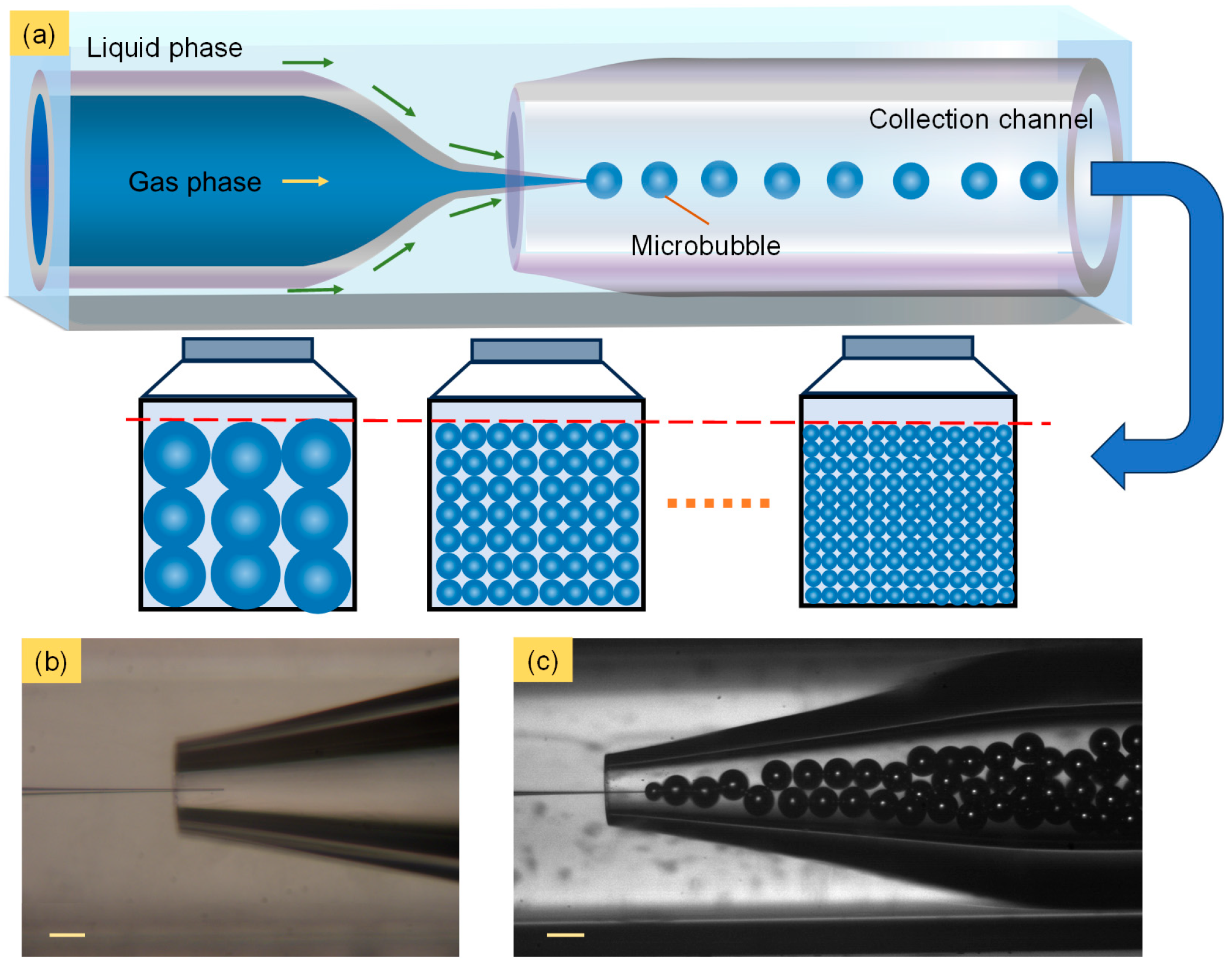
2.2. Fabrication of the Microbubble Generator

The microbubble generator was fabricated using a co-flowing microfluidic glass capillary device, as shown in Figure 1a. In detail, two cylindrical capillary glass tubes (1B100-6) were fitted into a square capillary glass tube (810-9917). The two cylindrical capillary glass tubes were tapered by a micropipette puller (P-1000, Sutter Instrument, Novato, CA, USA) and forged by a micro-forge (MF01-M4, China Jiliang University, Hangzhou, China) to 5 μm and 180 μm as the gas channel and the collection channel, respectively. The inner wall of the gas channel was treated with 1 wt% OTS solution to enhance its hydrophobic property. This device is similar to those used in some studies [41,42,43], all belonging to the category of co-flow systems. It is cost-effective and made entirely of glass, providing excellent compatibility with most fluids. The internal position parameters are highly controllable and can be adjusted according to different needs, making it widely applicable.

2.3. Generation Process of Microbubbles

In order to stabilize the process of microbubble generation, gas was supplied from a pressurized tank to the gas channel through a polytetrafluoroethylene (PTFE) soft tube. The gas pressure was controlled with a pressure regulating valve (152X-80, GENTEC Shanghai Co., Shanghai, China). The liquid phase (10 wt% PVA solution) was injected into the microbubble generator with a controlled flow rate using a microfluidic controller (PG-MFC series, Precigenome LLC, San Jose, CA, USA). Similar to the co-flowing droplet generation method, microbubbles were formed under the function of shear action of the liquid phase and Plateau–Rayleigh instability at the gas–liquid interface (Video S1). Meanwhile, the process of microbubble generation was captured by a high-speed camera (FASTCAM Mini UX 50, Photron, Tokyo, Japan) with a framerate speed of 5000 fps. Additionally, the generated microbubbles were collected and transferred to a glass culture bottle, where they were left for one minute to stabilize and captured using a COMS camera (Biohd-C12, Fluoca Scientific Co., Ltd., Shanghai, China) to present their morphology and cumulative volume. The PVA surfactant present in the liquid phase played an important role in avoiding the coalescence of collected microbubbles.

3. Results and Discussion

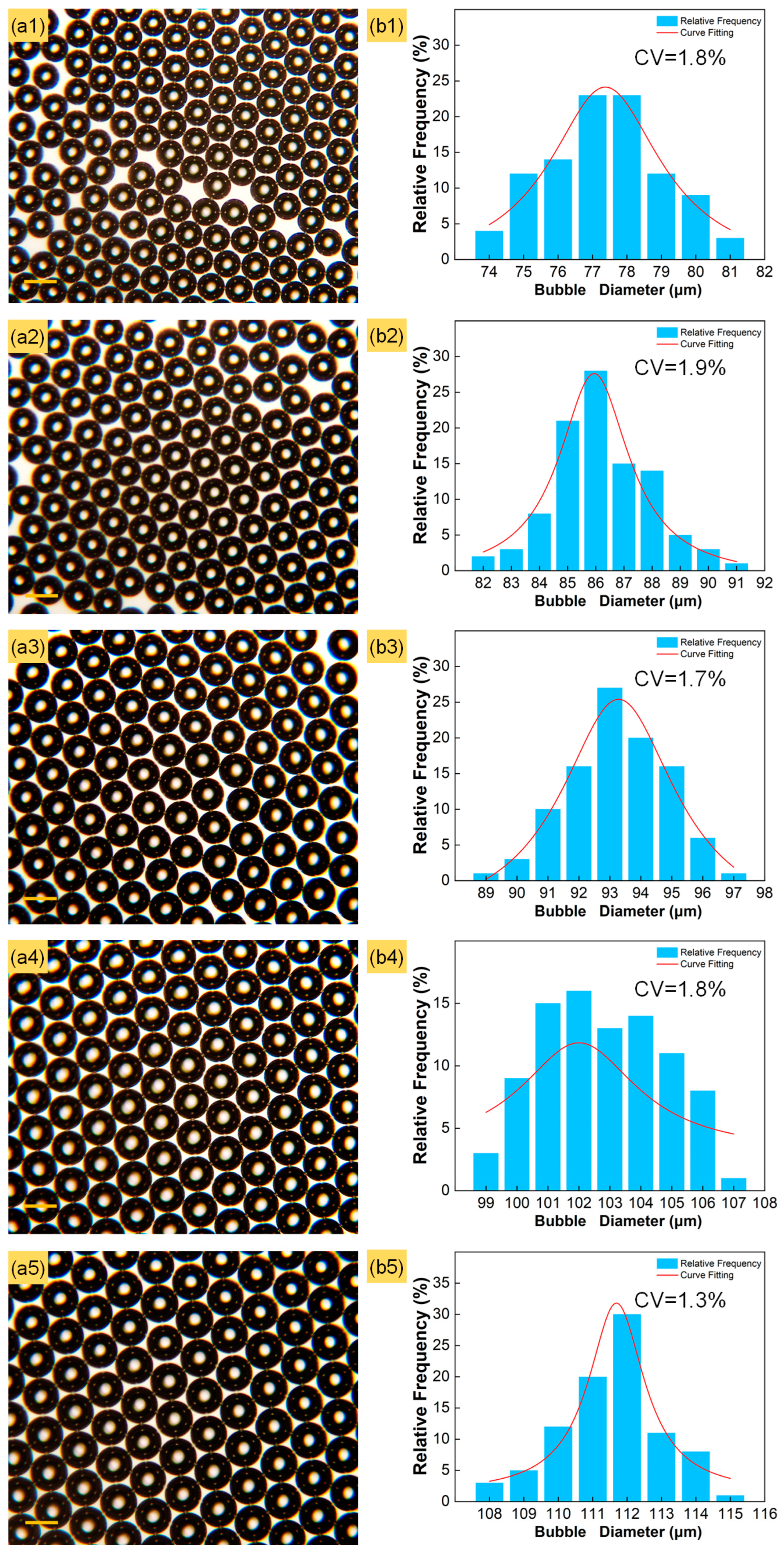
3.1. Uniformity of Microbubbles at Various Input Gas Pressures

For a given microbubble generator, the input gas pressure is a critical parameter to control the microbubble morphology. In this experiment, the diameter and distribution of generated microbubbles were calculated at various input gas pressures, as shown in Figure 2, where the gas channel orifice is 5 μm, the input gas pressure is 90 to 170 kPa in 20 kPa increments, and the liquid phase flow rate is maintained at 10 mL/h. In each experiment, 400 microbubbles were selected to analyze their diameters using Image J software (V 1.8.0).
With the increase in the input gas pressure, the diameter of the generated microbubbles increased from 76.87 to 110.02 μm, as shown in Figure 2(a1–a5). This trend is similar to the findings of previous researchers [44,45,46]. A higher input gas pressure results in a larger pressure difference at the tip of the gas channel, leading to a faster gas flow rate and bigger microbubble diameter. In order to demonstrate the uniformity of the generated microbubbles from a data perspective reliably, the distributions and the CVs of their diameters were calculated at different input gas pressures. The CV is calculated as follows:
CV = D st D av × 100 %
Dst and Dav are the standard deviation of the microbubbles’ diameters and the average microbubble diameter, respectively.
The CVs under different flow rates of the liquid phase were 1.8%, 1.9%, 1.7%, 1.8% and 1.3%, respectively, as shown in Figure 2(b1–b5). The majority of the generated microbubble diameters were distributed around the median, gradually decreasing within an interval length not exceeding 10 μm at each input gas pressure.

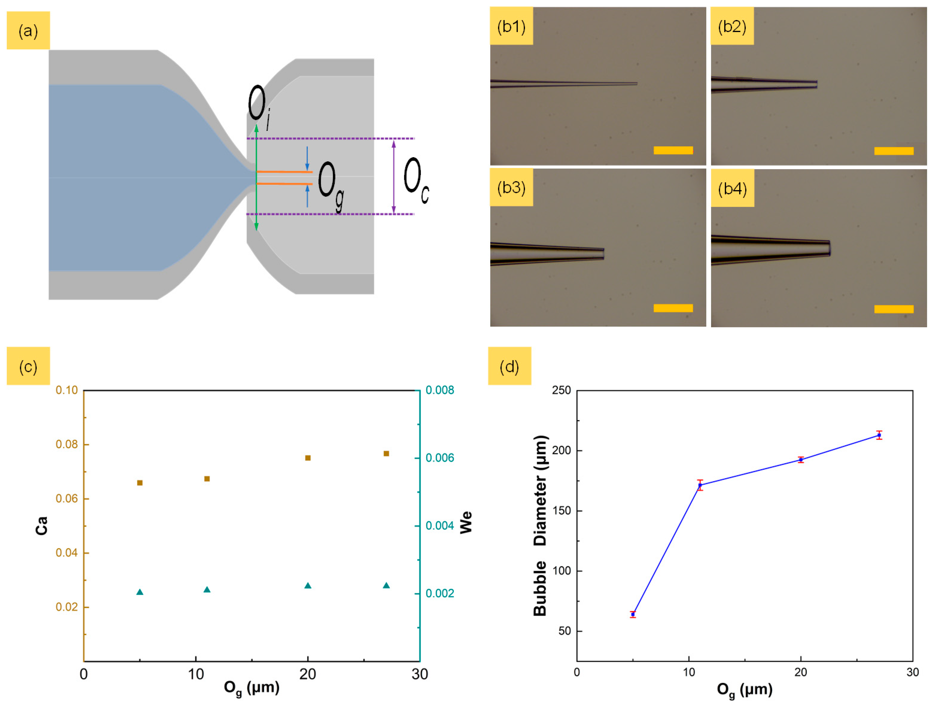
3.2. Effect of Different Gas Channel Orifices on Microbubble Diameter

The gas channel orifice has a significant effect on the distribution of the microbubbles’ diameters. To explore the influence of different orifices on microbubble diameter and ensure the consistency of other parameters, the capillary glass tubes were fixed in the bubble generator according to certain protocols, as shown in Figure 3a. Og and Oc represent the diameter of the gas channel and the collection channel, respectively. Oi represents the diameter of the cross-section at the junction of the two phases. Four gas channels with orifices (Og) of 5, 11, 20 and 29 μm were fabricated and fixed to microbubble generators, as shown in Figure 3(b1–b4). Here, Oc and Oi were maintained at 180 μm and 218 μm, respectively. The liquid flow rate and the input gas pressure were maintained at 20 mL/h and 60 kPa, respectively. The Capillary number (Ca = μU/σ) and Weber number (We = ρU2l/σ) are both critical parameters for microfluidic devices. Here, μ is the viscosity, σ is the surface tension coefficient, U is the characteristic velocity, ρ is the density and l is the characteristic length.
In this experiment, different orifices of gas channels resulted in a low We of about 0.002 and a Ca of about 0.007, as shown in Figure 3c. A larger orifice of the gas channel resulted in a larger microbubble diameter, increasing from 63.94 μm to 212.98 μm, as shown in Figure 3d. The orifice of the gas channel determines the pressure loss of gas and the action of liquid phase viscosity in tapered gas channels under constant flow conditions. As the orifice increased, more time was needed by the liquid phase viscosity to shear the gas column and form microbubbles.

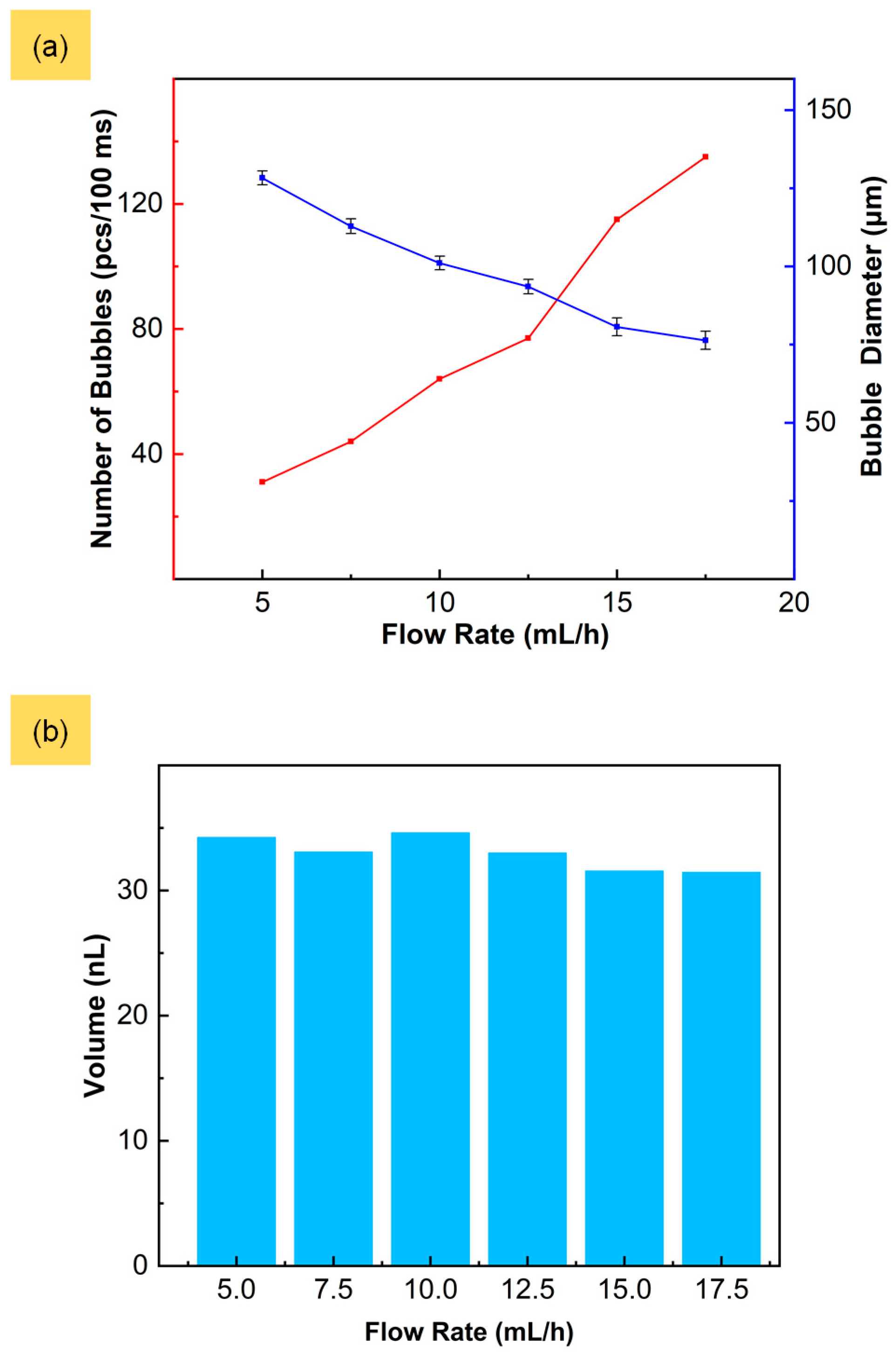
3.3. Constancy of Cumulative Microbubble Production at Various Liquid Phase Flow Rates

In conditions of constant input gas pressure, the cumulative microbubble production over a certain period of time remains invariant and unaffected by fluctuations in the flow rate of the liquid phase. This phenomenon can be demonstrated through an examination of both the frequency and diameter of the generated microbubbles at various flow rates of the liquid phase. In this experiment, the input pressure was maintained at 150 kPa, and the flow rate of the liquid phase was increased at 5 mL/h to 17.5 mL/h in 2.5 mL/h increments. Six sets of experiments were performed at each flow rate to obtain the average frequency and diameter of the generated microbubbles. With the increase in the liquid phase flow rate, the microbubbles’ diameters exhibited a downward trend that decreased gradually from 129.11 μm to 76.66 μm, and the frequency of generation increased by about three times, as shown in Figure 4a.
The viscous shear force and extrusion pressure of the liquid phase increase with a faster liquid phase flow rate, making it easier to overcome the interfacial tension of the two phases. This results in the gradual increase in the shear frequency and the decreased microbubble diameter at the capillary tip. In order to verify the constancy of cumulative microbubble production in such gas–liquid co-flowing microfluidic devices, the total volumes of generated microbubbles per 100 ms at various liquid phase flow rates were calculated, which were 34.23 nL, 33.06 nL, 34.60 nL, 32.98 nL, 31.54 nL and 31.45 nL, respectively, as shown in Figure 4b. The CV of the cumulative microbubble volume can reach 3.6%. The variations in the frequency and diameter of the generated microbubbles did not result in changes in the total volume, indicating that the cumulative microbubble production of the microbubble generator was not influenced by the liquid phase flow rate.

4. Conclusions

In this work, we have shown that by using a gas–liquid co-flowing microfluidic device, constant cumulative microbubble production can be achieved with a total volume of around 32.98 nL in 100 ms. The effects of the liquid flow rate, the input gas pressure, and the gas channel orifice on the distribution of the microbubbles’ diameters were explored. Uniform microbubbles can be easily fabricated with diameters between 50 μm and 220 μm by tuning the flow conditions and orifices, and the CV of the microbubbles was less than 1.9%. In addition, despite variations in the flow conditions, the uniformity of the microbubbles’ diameters and morphologic stability were consistently maintained. More importantly, even with variations in the flow rates of the liquid phase, the generated microbubbles maintained a consistent cumulative volume over a certain period time, with the CV reaching 3.6%. This paper demonstrates the robustness and reliability of the device in generating uniform microbubbles across different operating conditions. These results not only contribute to the development of microbubble-related technologies but also hold potential for the volume-dominated application of chromatographic analysis and the component analysis of natural gas. Introducing bubbles into gas chromatography analysis can increase the surface area for gas separation, thereby enhancing the sensitivity and resolution of the analysis. And bubbles can serve as reactors to catalyze or convert reactants in gas-phase reactions, enabling the analysis and detection of gas samples.

Supplementary Materials

The following supporting information can be downloaded at: https://www.mdpi.com/article/10.3390/mi15060752/s1, Video S1: Microbubble generation.

Author Contributions

Conceptualization, J.Y. and L.H.; formal analysis, J.Y., X.S. and H.Y.; investigation, J.Y.; resources, H.Y.; writing—original draft preparation, J.Y. and L.H.; writing—review and editing, L.H.; supervision, L.H.; project administration, F.B.; funding acquisition, W.C., J.N. and C.L. All authors have read and agreed to the published version of the manuscript.

Funding

This research was funded by the State Administration for Market Regulation science and technology project of China (Grant No. 2022MK035), the Heilongjiang Provincial Natural Science Foundation of China (Grant LH2020E036) and the National Natural Science Foundation of China (Grant No. 12272367).

Data Availability Statement

Data are contained within the article.

Conflicts of Interest

Author Xinggen Su was employed by the company Dalian Institute of Metrology Inspection and Testing Co., Ltd. The remaining authors declare that the research was conducted in the absence of any commercial or financial relationships that could be construed as a potential conflict of interest.

References

  1. Vilela, D.; Cossio, U.; Parmar, J.; Martinez-Villacorta, A.M.; Gomez-Vallejo, V.; Llop, J.; Sanchez, S. Medical Imaging for the Tracking of Micromotors. ACS Nano 2018, 12, 1220–1227. [Google Scholar] [CrossRef]
  2. Abenojar, E.C.; Nittayacharn, P.; de Leon, A.; Perera, R.; Wang, Y.; Bederman, I.; Exner, A.A. Effect of Bubble Concentration on the In Vitro and In Vivo Performance of Highly Stable Lipid Shell-Stabilized Micro- and Nanoscale Ultrasound Contrast Agents. Langmuir 2019, 35, 10192–10202. [Google Scholar] [CrossRef] [PubMed]
  3. Wang, Y.; Li, X.; Zhou, Y.; Huang, P.Y.; Xu, Y.H. Preparation of nanobubbles for ultrasound imaging and intracelluar drug delivery. Int. J. Pharmaceut. 2010, 384, 148–153. [Google Scholar] [CrossRef] [PubMed]
  4. Angilè, F.E.; Vargo, K.B.; Sehgal, C.M.; Hammer, D.A.; Lee, D. Recombinant Protein-Stabilized Monodisperse Microbubbles with Tunable Size Using a Valve-Based Microfluidic Device. Langmuir 2014, 30, 12610–12618. [Google Scholar] [CrossRef] [PubMed]
  5. Lin, H.; Chen, J.; Chen, C. A novel technology: Microfluidic devices for microbubble ultrasound contrast agent generation. Med. Biol. Eng. Comput. 2016, 54, 1317–1330. [Google Scholar] [CrossRef] [PubMed]
  6. Ullah, M.; Kodam, S.P.; Mu, Q.; Akbar, A. Microbubbles versus Extracellular Vesicles as Therapeutic Cargo for Targeting Drug Delivery. ACS Nano 2021, 15, 3612–3620. [Google Scholar] [CrossRef] [PubMed]
  7. Gao, Z.; Kennedy, A.M.; Christensen, D.A.; Rapoport, N.Y. Drug-loaded nano/microbubbles for combining ultrasonography and targeted chemotherapy. Ultrasonics 2008, 48, 260–270. [Google Scholar] [CrossRef] [PubMed]
  8. Jeong, J.; Jang, D.; Kim, D.; Lee, D.; Chung, S.K. Acoustic bubble-based drug manipulation: Carrying, releasing and penetrating for targeted drug delivery using an electromagnetically actuated microrobot. Sens. Actuators A Phys. 2020, 306, 111973. [Google Scholar] [CrossRef]
  9. Lu, T.; Fan, R.; Delgadillo, L.F.; Wan, J. Stabilization of carbon dioxide (CO2) bubbles in micrometer-diameter aqueous droplets and the formation of hollow microparticles. Lab Chip 2016, 16, 1587–1592. [Google Scholar] [CrossRef]
  10. Bang, J.H.; Suslick, K.S. Applications of Ultrasound to the Synthesis of Nanostructured Materials. Adv. Mater. 2010, 22, 1039–1059. [Google Scholar] [CrossRef]
  11. Brugarolas, T.; Tu, F.; Lee, D. Directed assembly of particles using microfluidic droplets and bubbles. Soft Matter 2013, 9, 9046. [Google Scholar] [CrossRef]
  12. Rodríguez-Rodríguez, J.; Sevilla, A.; Martínez-Bazán, C.; Gordillo, J.M. Generation of Microbubbles with Applications to Industry and Medicine. Annu. Rev. Fluid Mech. 2015, 47, 405–429. [Google Scholar] [CrossRef]
  13. Chong, W.K.; Papadopoulou, V.; Dayton, P.A. Imaging with ultrasound contrast agents: Current status and future. Abdom. Radiol. 2018, 43, 762–772. [Google Scholar] [CrossRef] [PubMed]
  14. Stride, E.; Edirisinghe, M. Novel microbubble preparation technologies. Soft Matter 2008, 4, 2350–2359. [Google Scholar] [CrossRef]
  15. Gao, Y.; Wu, M.R.; Lin, Y.; Xu, J. Trapping and control of bubbles in various microfluidic applications. Lab Chip 2020, 20, 4512–4527. [Google Scholar] [CrossRef] [PubMed]
  16. Zhao, C.L.; Xie, Y.L.; Mao, Z.M.; Zhao, Y.H.; Rufo, J.; Yang, S.K.; Guo, F.; Mai, J.D.; Huang, T.J. Theory and experiment on particle trapping and manipulation via optothermally generated bubbles. Lab Chip 2014, 14, 384–391. [Google Scholar] [CrossRef] [PubMed]
  17. Chen, C.R.; Karshalev, E.; Guan, J.G.; Wang, J. Magnesium-Based Micromotors: Water-Powered Propulsion, Multifunctionality, and Biomedical and Environmental Applications. Small 2018, 14, 1704252. [Google Scholar] [CrossRef] [PubMed]
  18. Jaszczur, M.; Młynarczykowska, A. A General Review of the Current Development of Mechanically Agitated Vessels. Processes 2020, 8, 982. [Google Scholar] [CrossRef]
  19. Maeda, Y.; Hosokawa, S.; Baba, Y.; Tomiyama, A.; Ito, Y. Generation mechanism of micro-bubbles in a pressurized dissolution method. Exp. Therm. Fluid Sci. 2015, 60, 201–207. [Google Scholar] [CrossRef]
  20. Davoodi, P.; Feng, F.; Xu, Q.X.; Yan, W.C.; Tong, Y.W.; Srinivasan, M.P.; Sharma, V.K.; Wang, C.H. Coaxial electrohydrodynamic atomization: Microparticles for drug delivery applications. J. Control. Release 2015, 205, 70–82. [Google Scholar] [CrossRef]
  21. Farook, U.; Stride, E.; Edirisinghe, M.J. Stability of microbubbles prepared by co-axial electrohydrodynamic atomisation. Eur. Biophys. J. Biophy. 2009, 38, 713–718. [Google Scholar] [CrossRef] [PubMed]
  22. Li, Y.K.; Wang, K.; Xu, J.H.; Luo, G.S. A capillary-assembled micro-device for monodispersed small bubble and droplet generation. Chem. Eng. J. 2016, 293, 182–188. [Google Scholar] [CrossRef]
  23. Fu, T.T.; Ma, Y.G. Bubble formation and breakup dynamics in microfluidic devices: A review. Chem. Eng. Sci. 2015, 135, 343–372. [Google Scholar] [CrossRef]
  24. Li, Y.Y.; Liu, X.M.; Huang, Q.; Ohta, A.T.; Arai, T. Bubbles in microfluidics: An all-purpose tool for micromanipulation. Lab Chip 2021, 21, 1016–1035. [Google Scholar] [CrossRef] [PubMed]
  25. Huerre, A.; Miralles, V.; Jullien, M.C. Bubbles and foams in microfluidics. Soft Matter 2014, 10, 6888–6902. [Google Scholar] [CrossRef]
  26. Stoffel, M.; Wahl, S.; Lorenceau, E.; Höhler, R.; Mercier, B.; Angelescu, D.E. Bubble Production Mechanism in a Microfluidic Foam Generator. Phys. Rev. Lett. 2012, 108, 198302. [Google Scholar] [CrossRef] [PubMed]
  27. Zhang, C.; Fu, T.T.; Zhu, C.Y.; Jiang, S.K.; Ma, Y.G.; Li, H.Z. Dynamics of bubble formation in highly viscous liquids in a flow-focusing device. Chem. Eng. Sci. 2017, 172, 278–285. [Google Scholar] [CrossRef]
  28. Chong, Z.Z.; Tor, S.B.; Loh, N.H.; Wong, T.N.; Gañán-Calvo, A.M.; Tan, S.H.; Nguyen, N.T. Acoustofluidic control of bubble size in microfluidic flow-focusing configuration. Lab Chip 2015, 15, 996–999. [Google Scholar] [CrossRef] [PubMed]
  29. Sheng, L.; Ma, L.; Chen, Y.; Deng, J.; Luo, G. A comprehensive study of droplet formation in a capillary embedded step T-junction: From squeezing to jetting. Chem. Eng. J. 2022, 427, 132067. [Google Scholar] [CrossRef]
  30. Pancholi, K.; Stride, E.; Edirisinghe, M. Dynamics of bubble formation in highly viscous liquids. Langmuir 2008, 24, 4388–4393. [Google Scholar] [CrossRef]
  31. Brugarolas, T.; Park, B.J.; Lee, M.H.; Lee, D. Generation of Amphiphilic Janus Bubbles and Their Behavior at an Air–Water Interface. Adv. Funct. Mater. 2011, 21, 3924–3931. [Google Scholar] [CrossRef]
  32. Wang, Z.L. Speed up bubbling in a tapered co-flow geometry. Chem. Eng. J. 2015, 263, 346–355. [Google Scholar] [CrossRef]
  33. Lin, X.; Bao, F.; Tu, C.; Yin, Z.; Gao, X.; Lin, J. Dynamics of bubble formation in highly viscous liquid in co-flowing microfluidic device. Microfluid Nanofluid 2019, 23, 74. [Google Scholar] [CrossRef]
  34. Zhang, J.M.; Li, E.Q.; Thoroddsen, S.T. A co-flow-focusing monodisperse microbubble generator. J. Micromech. Microeng. 2014, 24, 035008. [Google Scholar] [CrossRef]
  35. Wang, K.; Xie, L.S.; Lu, Y.C.; Luo, G.S. Generating microbubbles in a co-flowing microfluidic device. Chem. Eng. Sci. 2013, 100, 486–495. [Google Scholar] [CrossRef]
  36. Vagner, S.A.; Patlazhan, S.A.; Serra, C.A.; Funfschilling, D.; Kulichikhin, V.G. Dripping and jetting of semi-dilute polymer solutions co-flowing in co-axial capillaries. Phys. Fluids 2021, 33, 062002. [Google Scholar] [CrossRef]
  37. Lu, W.; Li, E.Q.; Gao, P. Generation of microbubbles via a tapered capillary. Phys. Fluids 2023, 35, 122103. [Google Scholar] [CrossRef]
  38. Segers, T.; de Rond, L.; de Jong, N.; Borden, M.; Versluis, M. Stability of Monodisperse Phospholipid-Coated Microbubbles Formed by Flow-Focusing at High Production Rates. Langmuir 2016, 32, 3937–3944. [Google Scholar] [CrossRef]
  39. Mei, L.P.; Jin, M.L.; Xie, S.T.; Yan, Z.B.; Wang, X.; Zhou, G.F.; van den Berg, A.; Shui, L.L. A simple capillary-based open microfluidic device for size on-demand high-throughput droplet/bubble/microcapsule generation. Lab Chip 2018, 18, 2806–2815. [Google Scholar] [CrossRef]
  40. Anna, S.L. Droplets and Bubbles in Microfluidic Devices. Annu. Rev. Fluid Mech. 2016, 48, 285–309. [Google Scholar] [CrossRef]
  41. Chung, K.Y.; Mishra, N.C.; Wang, C.C.; Lin, F.H.; Lin, K.H. Fabricating scaffolds by microfluidics. Biomicrofluidics 2009, 3, 2. [Google Scholar] [CrossRef] [PubMed]
  42. Pan, D.W.; Zhang, Y.J.; Zhang, T.X.; Li, B. Flow regimes of polymeric fluid droplet formation in a co-flowing microfluidic device. Colloid Interface Sci. Commun. 2021, 42, 100392. [Google Scholar] [CrossRef]
  43. Zhu, P.G.; Tang, X.; Wang, L.Q. Droplet generation in co-flow microfluidic channels with vibration. Microfluid Nanofluid 2016, 20, 47. [Google Scholar] [CrossRef]
  44. Bhunia, A.; Pais, S.C.; Kamotani, Y.; Kim, I.H. Bubble formation in a coflow configuration in normal and reduced gravity. AIChE J. 1998, 44, 1499–1509. [Google Scholar] [CrossRef]
  45. Sun, L.; Fan, M.; Yu, H.; Li, P.; Xu, J.; Qin, H.; Jiang, S. Microbubble characteristic in a co-flowing liquid in microfluidic chip. J. Dispers. Sci. Technol. 2019, 41, 992–1001. [Google Scholar] [CrossRef]
  46. Xiong, R.; Bai, M.; Chung, J.N. Formation of bubbles in a simple co-flowing micro-channel. J. Micromech. Microeng. 2007, 17, 1002–1011. [Google Scholar] [CrossRef]
Figure 1. Microfluidic approach for generation of microbubbles with constant cumulative production. (a) Schematic illustration of microbubble generator and cumulative production in same period of time. (b) Microscopy image of microfluidic glass capillary device. (c) Generation of microbubbles. Scale bars are 100 μm.
Micromachines 15 00752 g001
Figure 2. (a1a5) Variation in microbubble diameter with different input pressures of 90, 110, 130, 150 and 170 kPa, respectively. Scale bars are 100 μm. (b1b5) Diameter distribution of microbubbles corresponding to (a1a5).
Micromachines 15 00752 g002
Figure 3. Variation in microbubble diameters with different capillary orifices. (a) Diagram illustration of microbubble generator. (b1b4) Tapered gas channel with different orifices of 5, 11, 20 and 29 μm, respectively. Scale bars are 100 μm. (c) Ca and We at different gas channel orifices. (d) Diameter of microbubbles generated at different gas channel orifices.
Micromachines 15 00752 g003
Figure 4. (a) Number and diameter of microbubbles with different flow rates of liquid phase. (b) Cumulative microbubble production under different flow rates of liquid phase at gas input pressure of 150 kPa for 100 ms.
Micromachines 15 00752 g004
Disclaimer/Publisher’s Note: The statements, opinions and data contained in all publications are solely those of the individual author(s) and contributor(s) and not of MDPI and/or the editor(s). MDPI and/or the editor(s) disclaim responsibility for any injury to people or property resulting from any ideas, methods, instructions or products referred to in the content.

