
Jet Electroforming of High-Aspect-Ratio Microcomponents by Periodically Lifting a Necked-Entrance Through-Mask

Abstract
:1. Introduction
2. Simulation Analysis
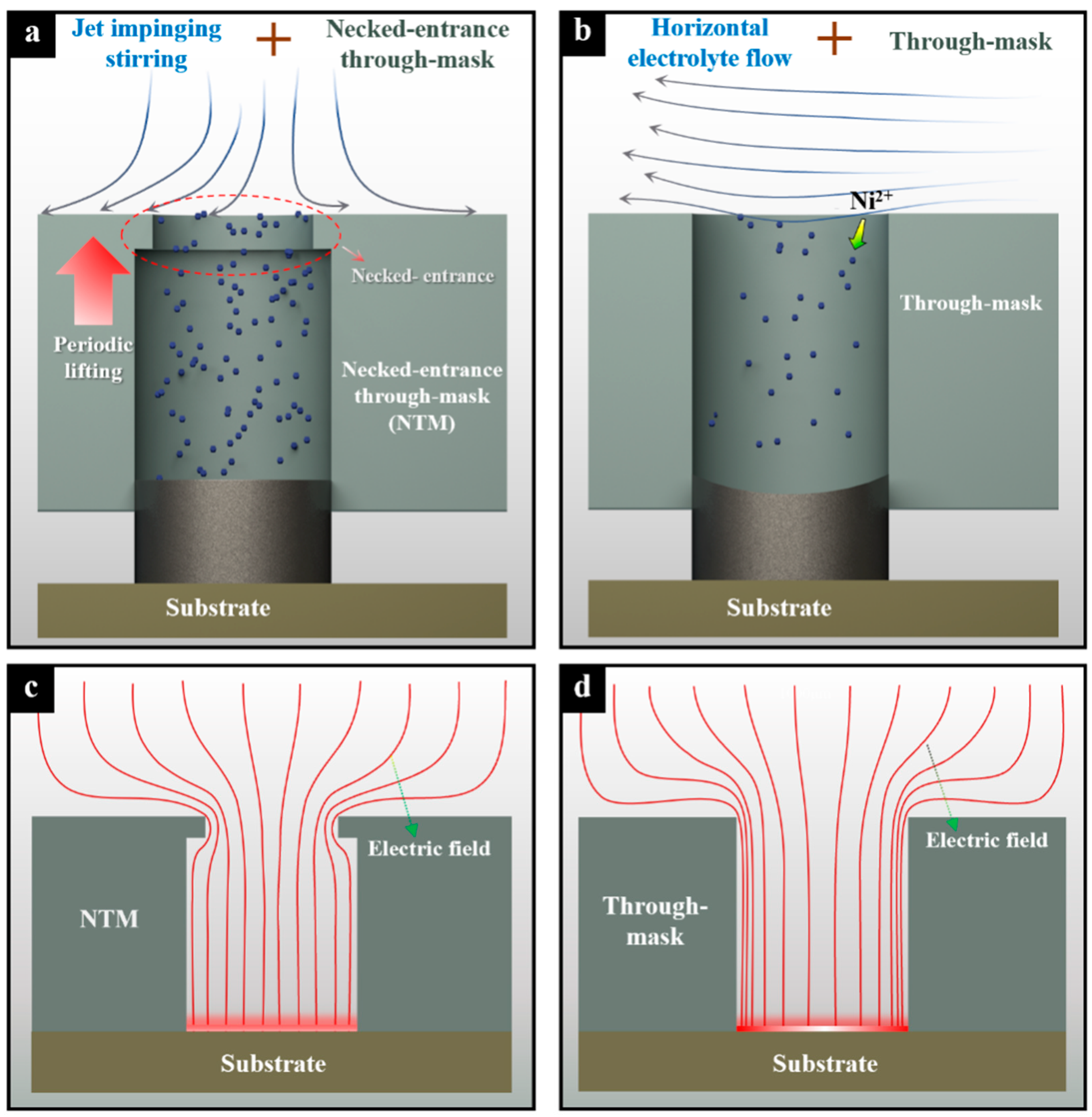
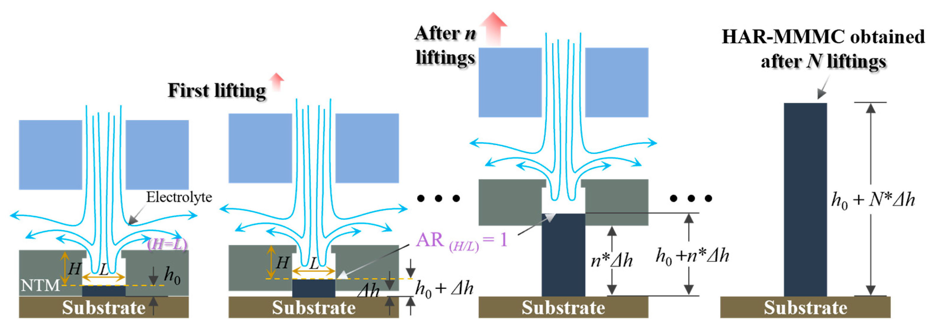
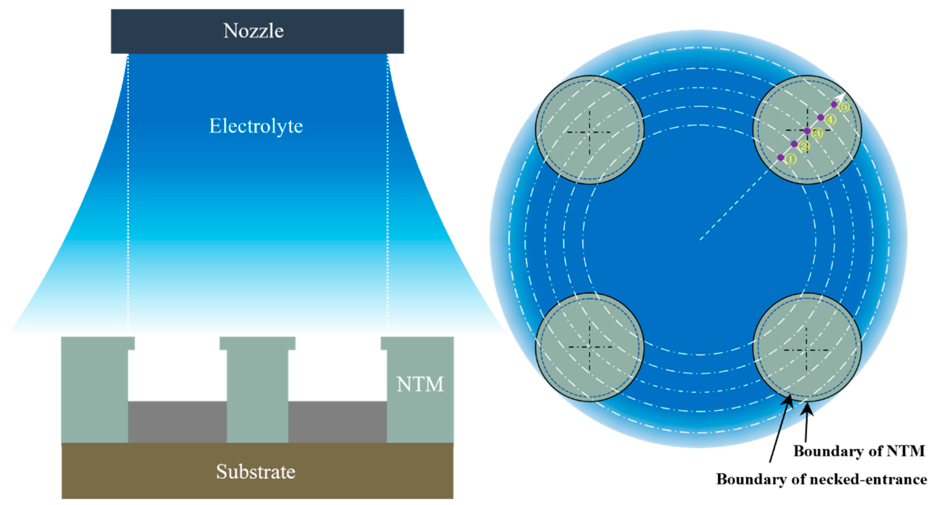
2.1. Principle of Periodically Lifting NTM-EF
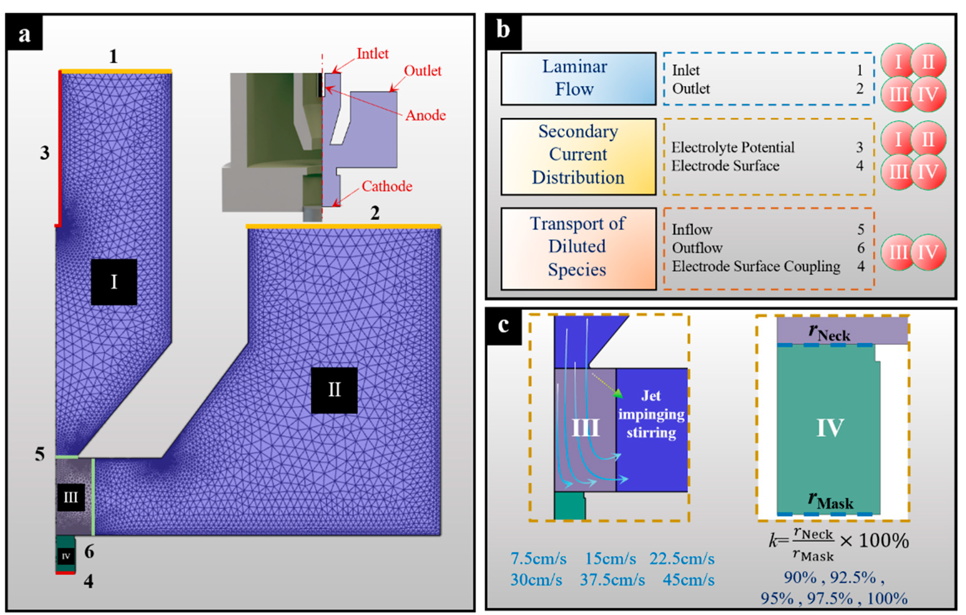
2.2. Simulation
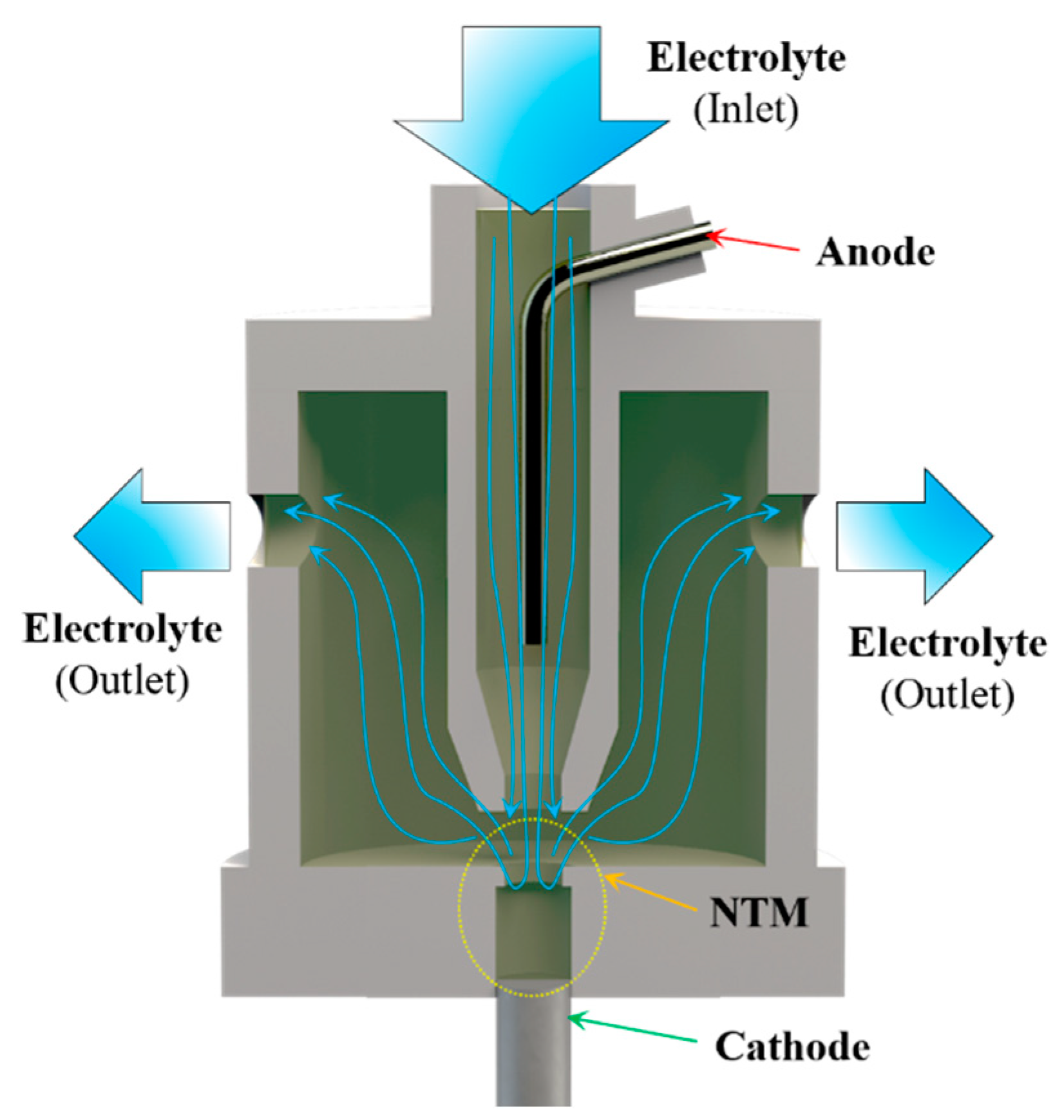
2.2.1. Models
2.2.2. Simulations
- (1)
- The electrolyte is a continuous incompressible viscous fluid.
- (2)
- The anode reaction is ignored, and the electrolyte potential is used as the anode boundary condition.
- (3)
- The cathode reaction is nickel electrodeposition, ignoring cathode side reactions, and obeys Faraday’s law. The primary objective of the numerical simulations in this study is to investigate the effects of different necked-entrance parameters. These parameters affect the distribution of current density on the cathode surface and the mass transfer within the through-mask cavities. This study does not focus on the deposition efficiency of metal ions. Therefore, disregarding the cathodic side reactions is appropriate to meet the research objectives.
- (4)
- The deposition surface of the microcomponent is at a stable position with an aspect ratio of the through-mask cavity of 1.
2.3. Simulation Results and Discussion
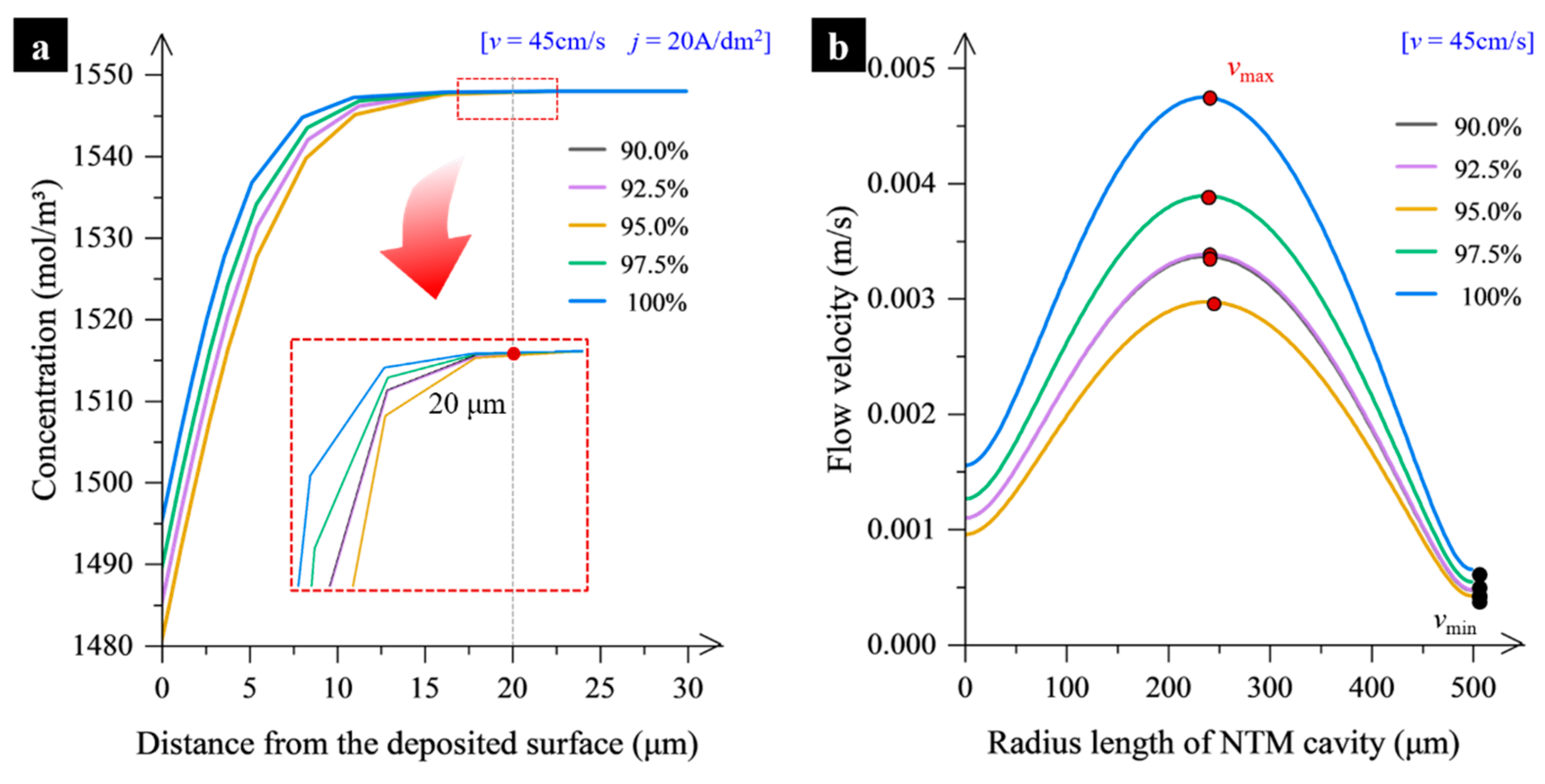
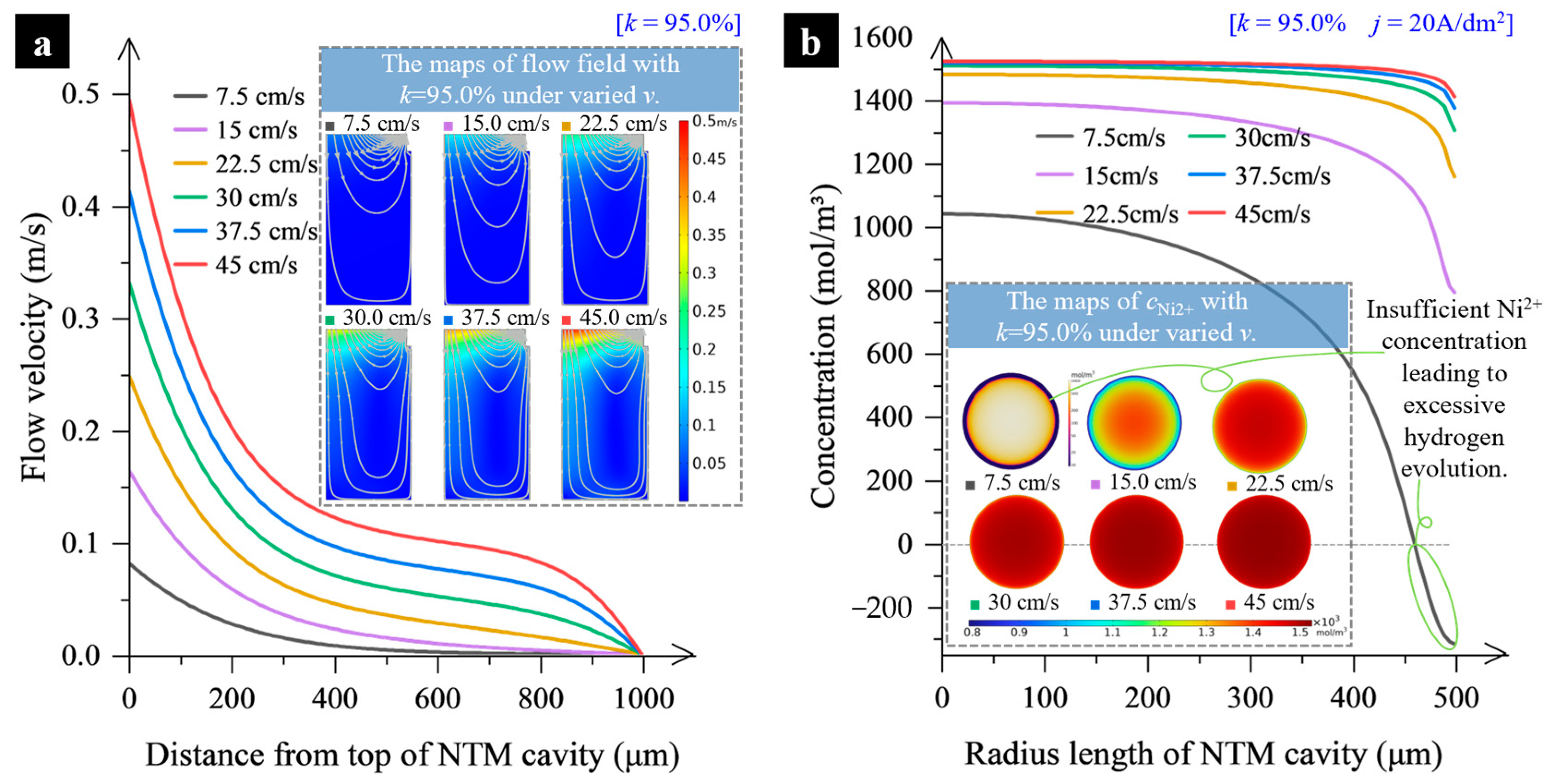
2.3.1. Effect of Mass Transfer
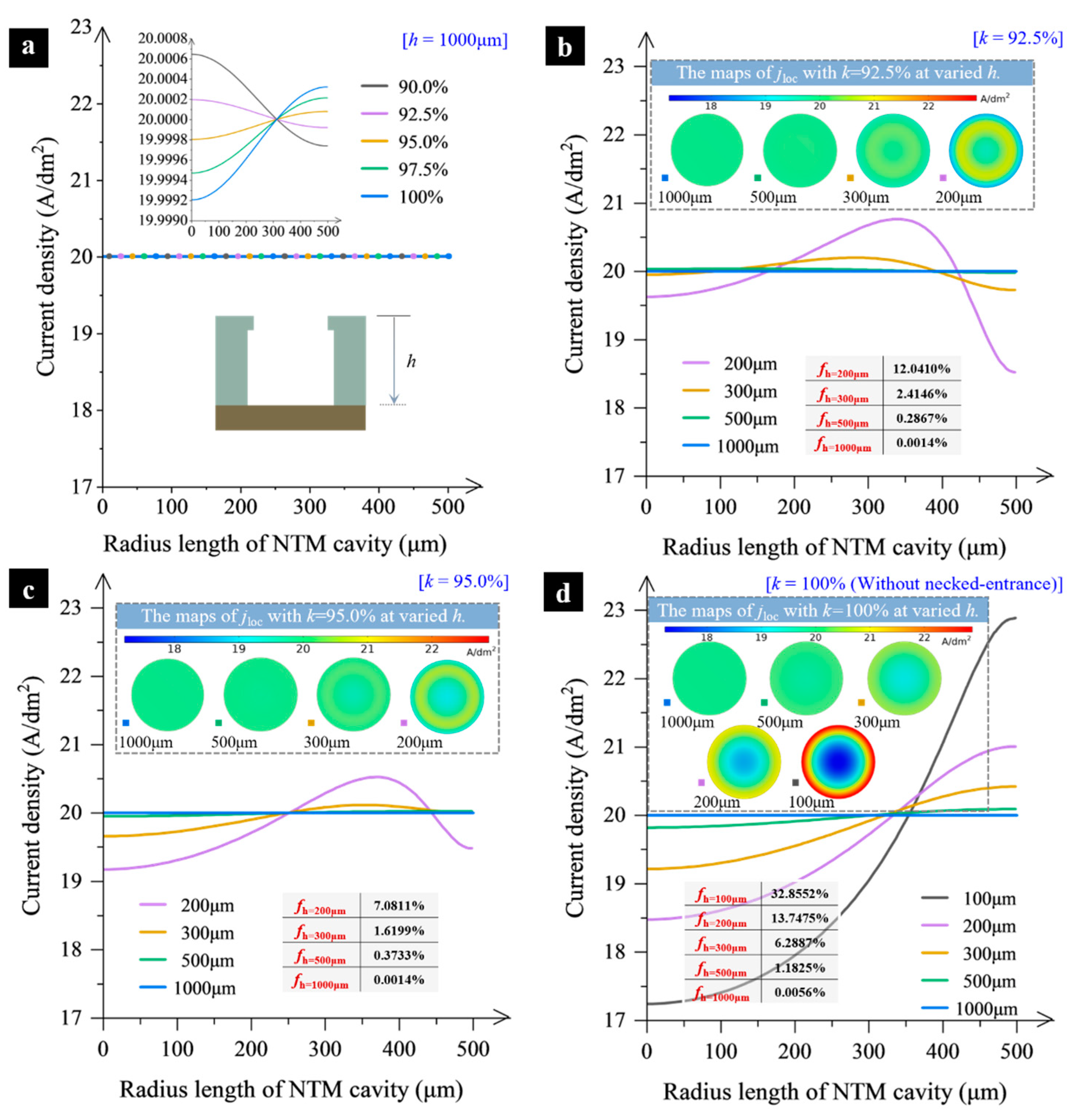
2.3.2. Electric Current Density Distribution
3. Experimental Study
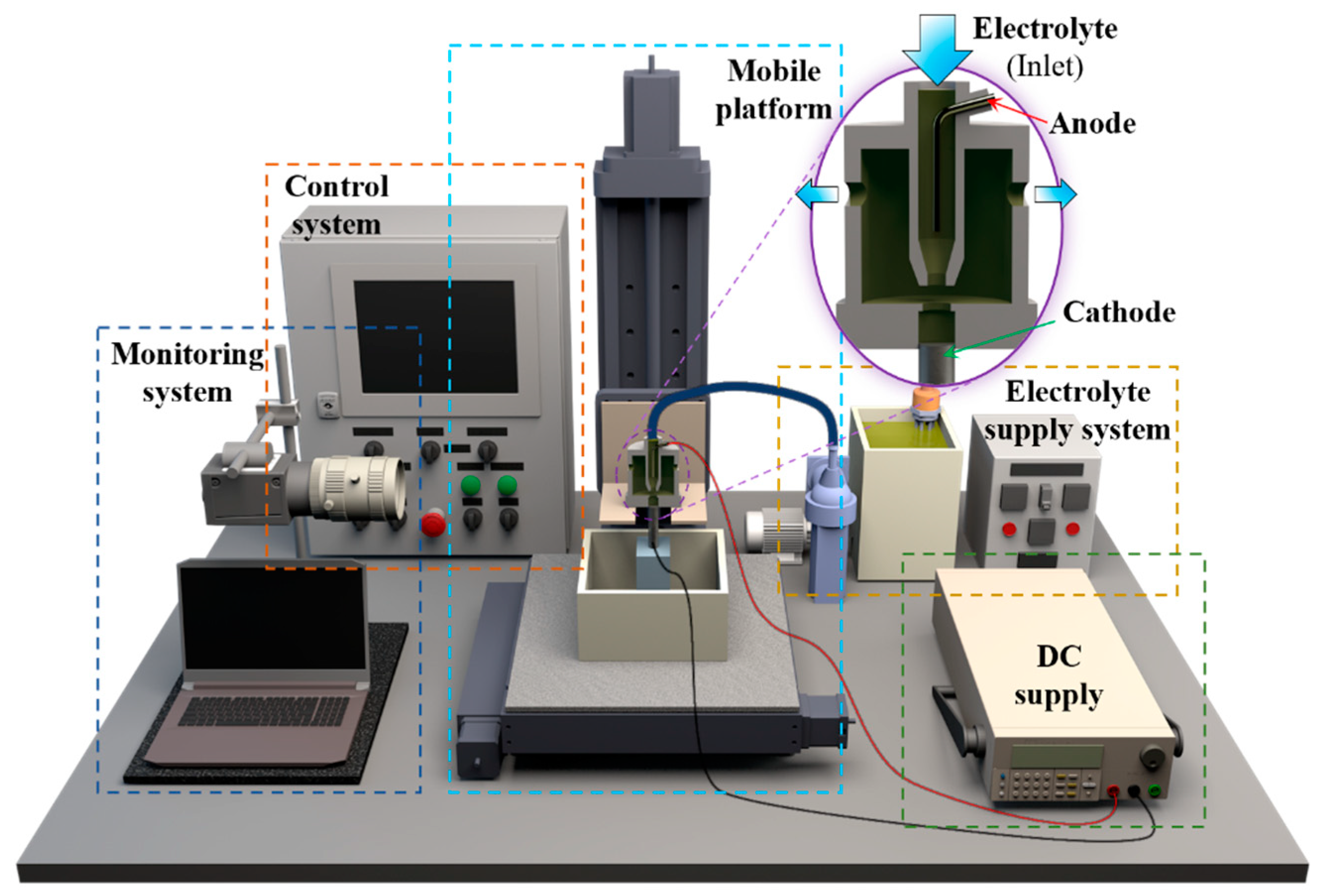
3.1. Materials and Methods
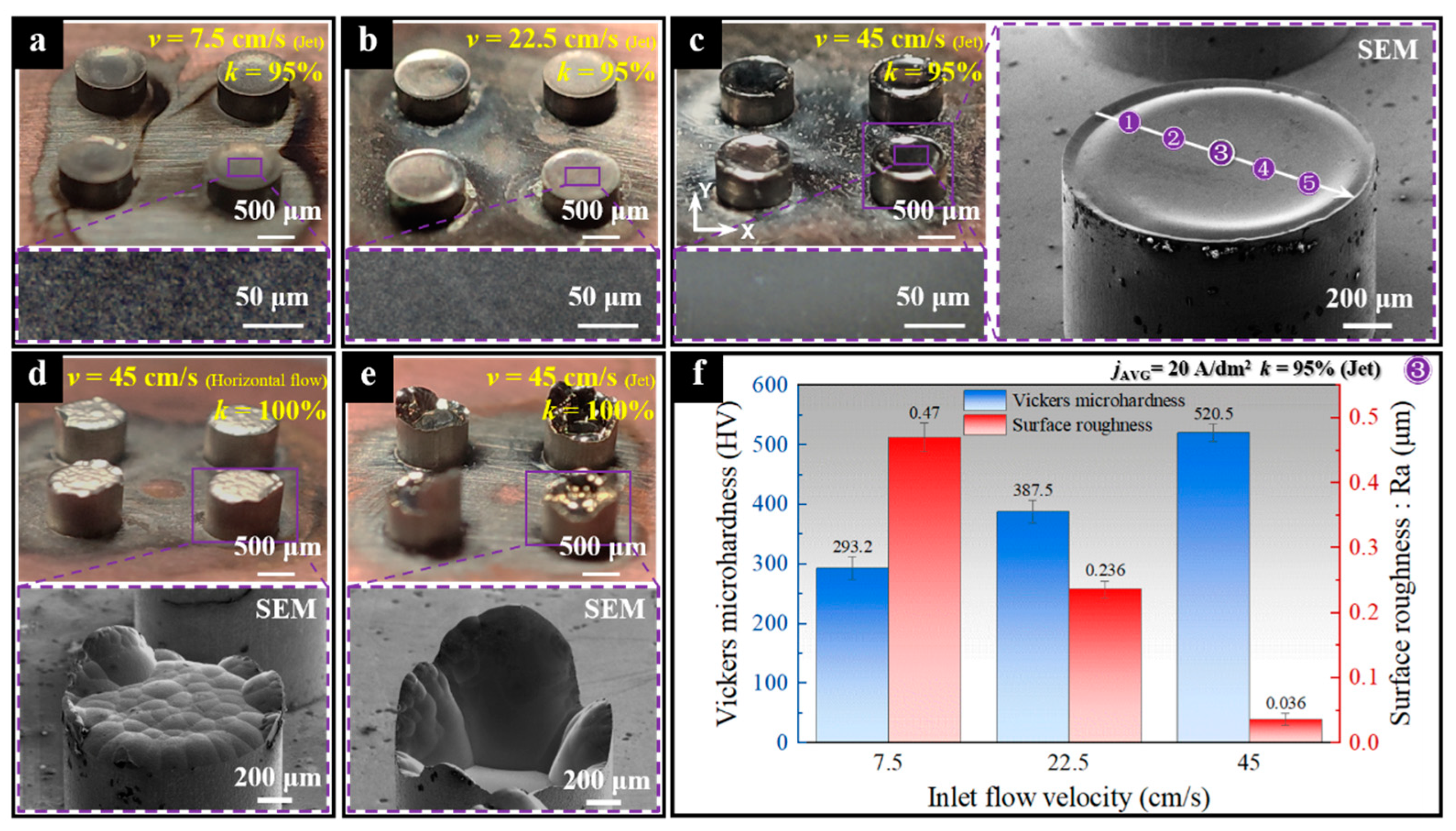
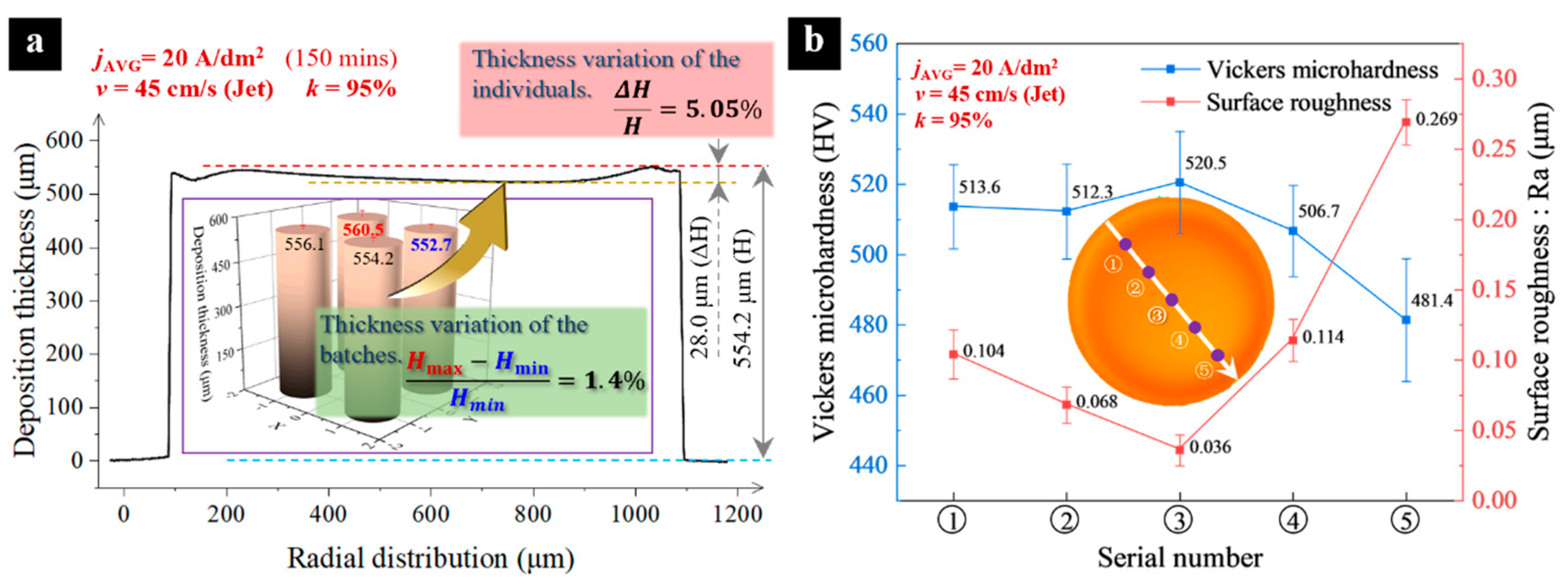
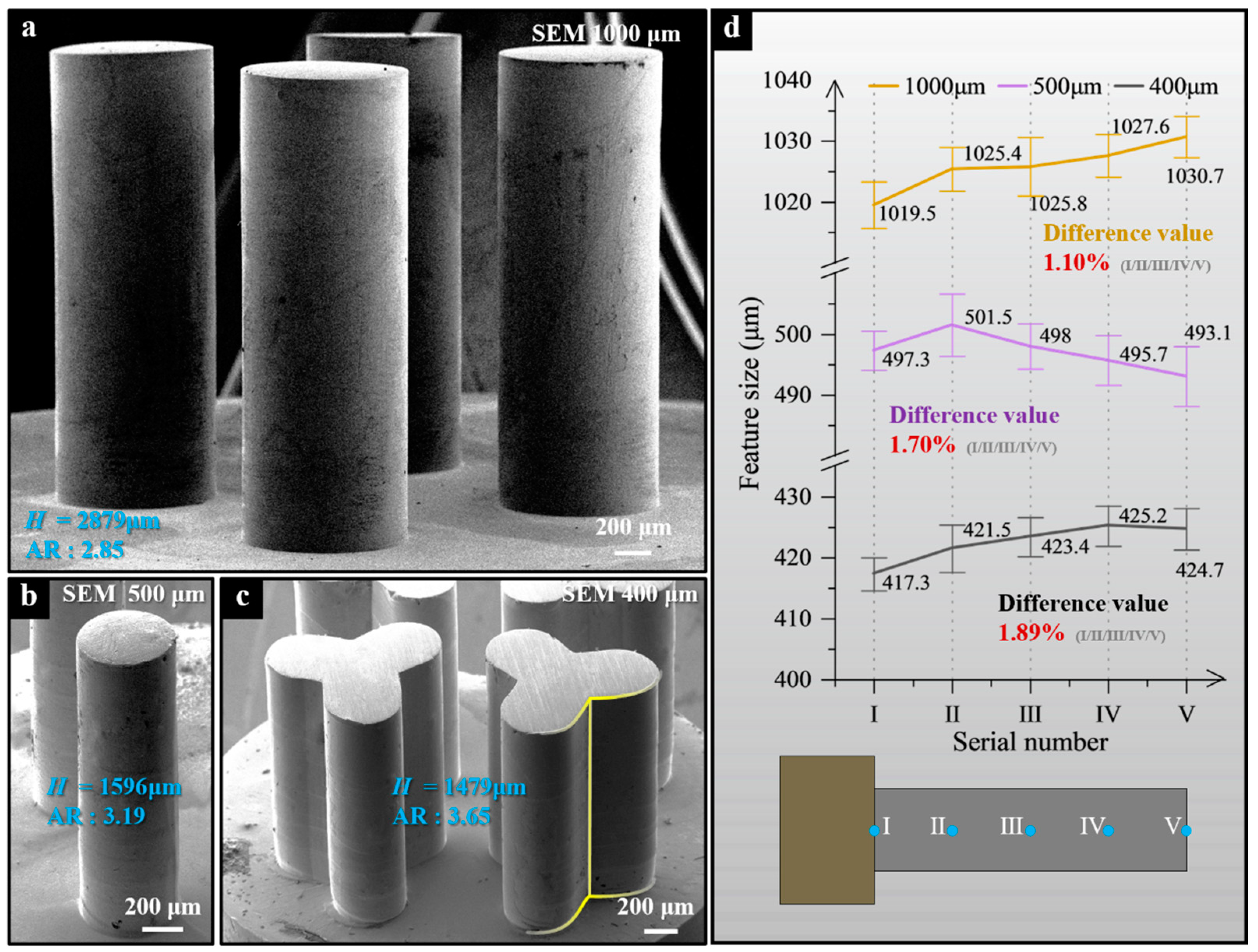
3.2. Experimental Results and Discussion
4. Conclusions
- (1)
- The periodically lifting NTM-EF process is feasible and effective for fabricating the precision HAR-MMMCs with a relatively high deposition rate.
- (2)
- In the periodically lifting NTM-EF, the necking size of the through-mask cavity mold is crucial to achieve an evenly-distributed thickness of top-growing surface, and, generally, a slight necking of less than 10% is preferable.
- (3)
- In the periodically lifting NTM-EF, a relatively higher speed of vertical impinging jet supply is necessary to quicken and homogenize mass transfer within the TM mold cavities.
Author Contributions
Funding
Data Availability Statement
Conflicts of Interest
References
- Gu, Q.; Lv, J.; Mo, X.; Jiang, X. High Aspect Ratio Metamaterials and Their Applications. Sens. Actuator A-Phys. 2022, 335, 113376. [Google Scholar] [CrossRef]
- Noda, D.; Hattori, T. Fabrication of Microcoils with Narrow and High Aspect Ratio Coil Line. Adv. Robot. 2010, 24, 1461–1470. [Google Scholar] [CrossRef]
- Park, J.M.; Kim, J.H.; Han, J.S.; Shin, D.S.; Park, S.C.; Son, S.H.; Park, S.J. Fabrication of Tapered Micropillars with High Aspect-Ratio Based on Deep X-Ray Lithography. Materials 2019, 12, 2056. [Google Scholar] [CrossRef] [PubMed]
- Kamaraj, A.B.; Sundaram, M.M.; Mathew, R. Ultra High Aspect Ratio Penetrating Metal Microelectrodes for Biomedical Applications. Microsyst. Technol. 2013, 19, 179–186. [Google Scholar] [CrossRef]
- Chen, S. Fabrication of High-Density Micro Holes by Upward Batch Micro EDM. J. Micromech. Microeng. 2008, 18, 085002. [Google Scholar] [CrossRef]
- Chang, D.-Y.; Lin, C.-H. High-Aspect Ratio Mechanical Microdrilling Process for a Microhole Array of Nitride Ceramics. Int. J. Adv. Manuf. Technol. 2019, 100, 2867–2883. [Google Scholar] [CrossRef]
- Yadroitsev, I.; Shishkovsky, I.; Bertrand, P.; Smurov, I. Manufacturing of Fine-Structured 3D Porous Filter Elements by Selective Laser Melting. Appl. Surf. Sci. 2009, 255, 5523–5527. [Google Scholar] [CrossRef]
- Guo, C.; Ge, W.; Lin, F. Effects of Scanning Parameters on Material Deposition during Electron Beam Selective Melting of Ti-6Al-4V Powder. J. Mater. Process. Technol. 2015, 217, 148–157. [Google Scholar] [CrossRef]
- Khademzadeh, S.; Zanini, F.; Bariani, P.F.; Carmignato, S. Precision Additive Manufacturing of NiTi Parts Using Micro Direct Metal Deposition. Int. J. Adv. Manuf. Technol. 2018, 96, 3729–3736. [Google Scholar] [CrossRef]
- Li, X.; Ming, P.; Ao, S.; Wang, W. Review of Additive Electrochemical Micro-Manufacturing Technology. Int. J. Mach. Tools Manuf. 2022, 173, 103848. [Google Scholar] [CrossRef]
- Davydov, A.D.; Volgin, V.M. Template Electrodeposition of Metals. Review. Russ. J. Electrochem. 2016, 52, 806–831. [Google Scholar] [CrossRef]
- Zhang, H.; Zhang, N.; Gilchrist, M.; Fang, F. Advances in Precision Micro/Nano-Electroforming: A State-of-the-Art Review. J. Micromech. Microeng. 2020, 30, 103002. [Google Scholar] [CrossRef]
- Wang, W.; Ming, P.; Zhang, X.; Li, X.; Zhang, Y.; Niu, S.; Ao, S. Additive Manufacturing of Three-Dimensional Intricate Microfeatures by Electrolyte-Column Localized Electrochemical Deposition. Addit. Manuf. 2022, 50, 102582. [Google Scholar] [CrossRef]
- Kim, H.; Kim, J.G.; Park, J.W.; Chu, C.N. Selective Copper Metallization of Nonconductive Materials Using Jet-Circulating Electrodeposition. Precis. Eng. 2018, 51, 153–159. [Google Scholar] [CrossRef]
- Volgin, V.M.; Kabanova, T.B.; Davydov, A.D. Modeling of Local Maskless Electrochemical Deposition of Metal Microcolumns. Chem. Eng. Sci. 2018, 183, 123–135. [Google Scholar] [CrossRef]
- Li, X.; Ming, P.; Zhang, X.; Wang, W.; Zhang, Y.; Qin, G.; Zheng, X.; Niu, S. Compressed Air-Film Encircling Jet Electrodeposition with High Deposition Accuracy. J. Electrochem. Soc. 2020, 167, 102502. [Google Scholar] [CrossRef]
- Li, S.; Ming, P.; Zhang, J.; Zhang, Y.; Yan, L. Concurrently Fabricating Precision Meso- and Microscale Cross-Scale Arrayed Metal Features and Components by Using Wire-Anode Scanning Electroforming Technique. Micromachines 2023, 14, 979. [Google Scholar] [CrossRef] [PubMed]
- Becker, E.W.; Ehrfeld, W.; Hagmann, P.; Maner, A.; Münchmeyer, D. Fabrication of Microstructures with High Aspect Ratios and Great Structural Heights by Synchrotron Radiation Lithography, Galvanoforming, and Plastic Moulding (LIGA Process). Microelectron. Eng. 1986, 4, 35–56. [Google Scholar] [CrossRef]
- Weng, C.; Zhou, M.; Jiang, B.; Lv, H. Improvement on Replication Quality of Electroformed Nickel Mold Inserts with Micro/Nano-Structures. Int. Commun. Heat Mass Transf. 2016, 75, 92–99. [Google Scholar] [CrossRef]
- Zhang, H.; Zhang, N.; Fang, F. Study of Ion Transportation and Electrodeposition under Hybrid Agitation for Electroforming of Variable Aspect Ratios Micro Structures. Precis. Eng. 2021, 72, 122–143. [Google Scholar] [CrossRef]
- Zhang, H.; Zhang, N.; Fang, F. Investigation of Mass Transfer inside Micro Structures and Its Effect on Replication Accuracy in Precision Micro Electroforming. Int. J. Mach. Tools Manuf. 2021, 165, 103717. [Google Scholar] [CrossRef]
- Du, L.; Yuan, B.; Guo, B.; Wang, S.; Cai, X. Fabrication of High-Aspect-Ratio Stepped Cu Microcolumn Array Using UV-LIGA Technology. Microsyst. Technol. 2023, 29, 999–1014. [Google Scholar] [CrossRef]
- Miao, Z.-W.; Liu, Z.; Hao, Z.-C.; Zeng, Y.; Zhu, D.; Zhao, J.-H.; Ding, C.-Y.; Cheng, L.; Zhao, L.; Hong, W. A 1.0-THz High-Gain Metal-Only Transmit-Array Antenna Based on High-Precision UV-LIGA Microfabrication Technology. IEEE Trans. Terahertz Sci. Technol. 2024, 14, 269–282. [Google Scholar] [CrossRef]
- Chung, C.K.; Syu, Y.J.; Wang, H.Y.; Cheng, C.C.; Lin, S.L.; Tu, K.Z. Fabrication of Flexible Light Guide Plate Using CO2 Laser LIGA-like Technology. Microsyst. Technol. 2013, 19, 439–443. [Google Scholar] [CrossRef]
- Rasmussen, K.H.; Keller, S.S.; Jensen, F.; Jorgensen, A.M.; Hansen, O. SU-8 Etching in Inductively Coupled Oxygen Plasma. Microelectron. Eng. 2013, 112, 35–40. [Google Scholar] [CrossRef]
- Zhu, D.; Zeng, Y.B. Micro Electroforming of High-Aspect-Ratio Metallic Microstructures by Using a Movable Mask. CIRP Ann. 2008, 57, 227–230. [Google Scholar] [CrossRef]
- Yang, G.; Deng, D.; Zhang, Y.; Zhu, Q.; Cai, J. Numerical Optimization of Electrodeposition Thickness Uniformity with Respect to the Layout of Anode and Cathode. Electrocatalysis 2021, 12, 478–488. [Google Scholar] [CrossRef]
- Zhang, H.; Zhang, N.; Fang, F. Study on Controllable Thickness and Flatness of Wafer-Scale Nickel Shim in Precision Electroforming Process: Simulation and Validation. J. Manuf. Sci. Eng. 2021, 143, 111005. [Google Scholar] [CrossRef]
- Yao, Y.; Rodriguez, J.; Cui, J.; Lennon, A.; Wenham, S. Uniform Plating of Thin Nickel Layers for Silicon Solar Cells. Energy Procedia 2013, 38, 807–815. [Google Scholar] [CrossRef]
- Flott, L.W. The Challenge of Thickness Variation in Plating and Anodizing. Met. Finish. 2012, 110, 33–35. [Google Scholar] [CrossRef]
- Li, B.; Mei, T.; Chu, H.; Wang, J.; Du, S.; Miao, Y.; Zhang, W. Ultrasonic-Assisted Electrodeposition of Ni/Diamond Composite Coatings and Its Structure and Electrochemical Properties. Ultrason. Eonothem. 2021, 73, 105475. [Google Scholar] [CrossRef]
- Foias, C.; Temam, R. Gevrey Class Regularity for the Solutions of the Navier-Stokes Equations. J. Funct. Anal. 1989, 87, 359–369. [Google Scholar] [CrossRef]
- Grande, W.C.; Talbot, J.B. Electrodeposition of Thin Films of Nickel-Iron: II. Modeling. J. Electrochem. Soc. 1993, 140, 675. [Google Scholar] [CrossRef]
- Wang, H.; Xie, J.; Fan, T.; Sun, D.; Li, C. Improving the Thickness Uniformity of Micro Gear by Multi-Step, Self-Aligned Lithography and Electroforming. Micromachines 2023, 14, 775. [Google Scholar] [CrossRef] [PubMed]
- Xiao, Y.; Ming, P.; Zhang, X.; Hou, Y.; Du, L.; Li, S.; Zhang, Y.; Song, J. Ultrahigh Strength Ultrapure Nanostructured Nickel Metal Prepared via Ultrafine Anode Scanning Electrodeposition. Mater. Des. 2022, 213, 110339. [Google Scholar] [CrossRef]

| Parameter | Nomenclature | Value |
|---|---|---|
| Electrolyte temperature (°C) | T | 55 |
| Anodic charge transfer coefficient | αa | 1.5 |
| Cathodic charge transfer coefficient | αc | 0.5 |
| Cathodic current density (A/dm2) | j | 20 |
| Electrolyte conductivity (S/m) | σ | 10 |
| Concentration of Ni2+ (mol/m3) | c | 1548 |
| Electrolyte flow (cm/s) | v | 7.5, 15, 22.5, 30, 37.5, 45 |
| Electrolyte viscosity (Pa·s) | μ | 1.2 × 10⁻⁴ |
| Electrolyte density (kg/m3) | ρ | 1400 |
| Radius of through-mask cavity (μm) | rMask | 1000 |
| rNeck/rMask × 100% | k | 90%, 92.5%, 95%, 97.5%, 100% |
Disclaimer/Publisher’s Note: The statements, opinions and data contained in all publications are solely those of the individual author(s) and contributor(s) and not of MDPI and/or the editor(s). MDPI and/or the editor(s) disclaim responsibility for any injury to people or property resulting from any ideas, methods, instructions or products referred to in the content. |
© 2024 by the authors. Licensee MDPI, Basel, Switzerland. This article is an open access article distributed under the terms and conditions of the Creative Commons Attribution (CC BY) license (https://creativecommons.org/licenses/by/4.0/).
Share and Cite
Zhang, Y.; Ming, P.; Zhang, X.; Li, X.; Li, L.; Yang, Z. Jet Electroforming of High-Aspect-Ratio Microcomponents by Periodically Lifting a Necked-Entrance Through-Mask. Micromachines 2024, 15, 753. https://doi.org/10.3390/mi15060753
Zhang Y, Ming P, Zhang X, Li X, Li L, Yang Z. Jet Electroforming of High-Aspect-Ratio Microcomponents by Periodically Lifting a Necked-Entrance Through-Mask. Micromachines. 2024; 15(6):753. https://doi.org/10.3390/mi15060753
Chicago/Turabian StyleZhang, Yasai, Pingmei Ming, Xinmin Zhang, Xinchao Li, Lunxu Li, and Zheng Yang. 2024. "Jet Electroforming of High-Aspect-Ratio Microcomponents by Periodically Lifting a Necked-Entrance Through-Mask" Micromachines 15, no. 6: 753. https://doi.org/10.3390/mi15060753