

Dual Features, Compact Dimensions and X-Band Applications for the Design and Fabrication of Annular Circular Ring-Based Crescent-Moon-Shaped Microstrip Patch Antenna
 , , , , and
Abstract
:1. Introduction
Main Contribution
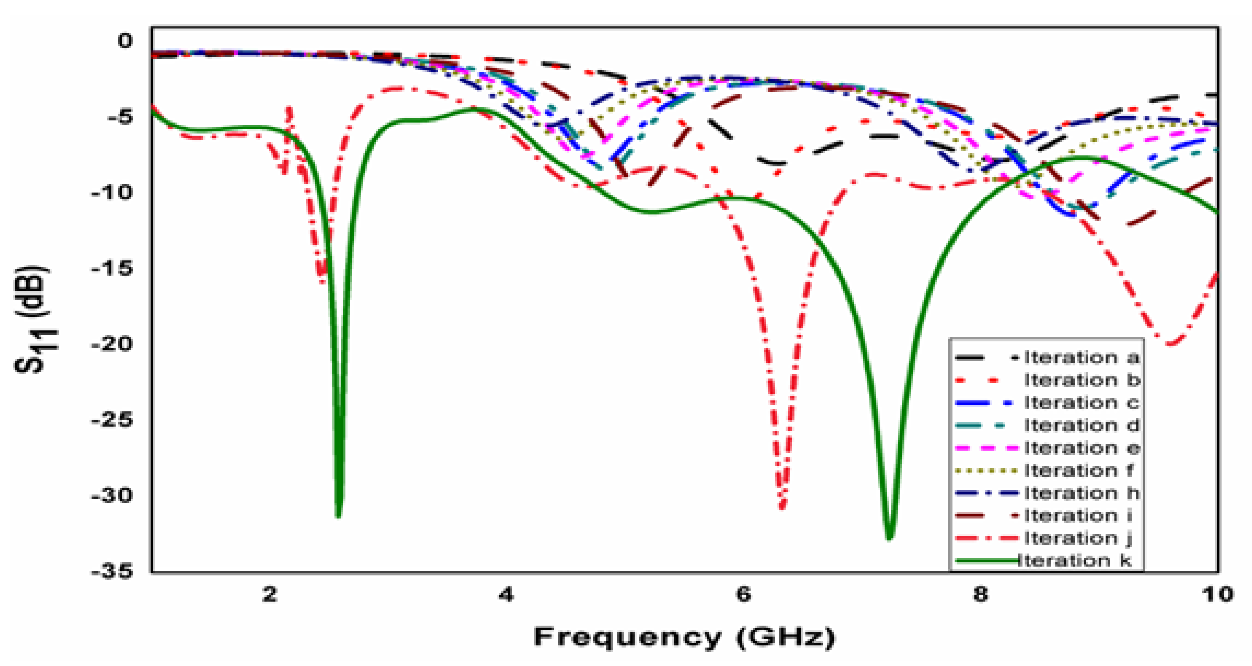
- This study introduces a novel multi-band antenna design by integrating annular circular rings into a crescent-shaped patch antenna, achieving dual-band operation at 3.1 GHz and 9.3 GHz with significant return loss values of −33 dB and −22 dB, respectively.
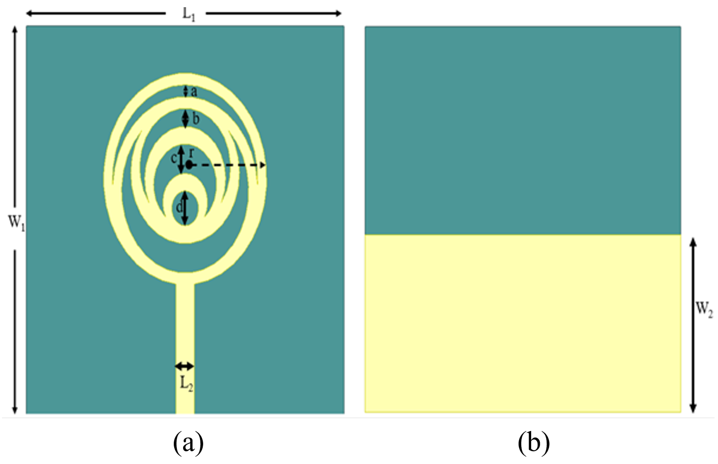
- The proposed antenna design employs five nested circular annular rings, with a specific arrangement of three rings on top and two rings along the bottom of the feed line, enhancing its multi-band capabilities and compactness.
- Simulation and experimental results, conducted using ANSYS HFSS 2024 R1, demonstrate excellent agreement, validating the design’s performance in terms of return loss, bandwidth, gain, and impedance.
- The antenna achieves wide impedance bandwidths of 0.4 GHz (2.8–3.2 GHz) and 4.29 GHz (6.16–10.45 GHz), covering critical frequency bands for wireless applications and X-band satellite communication.
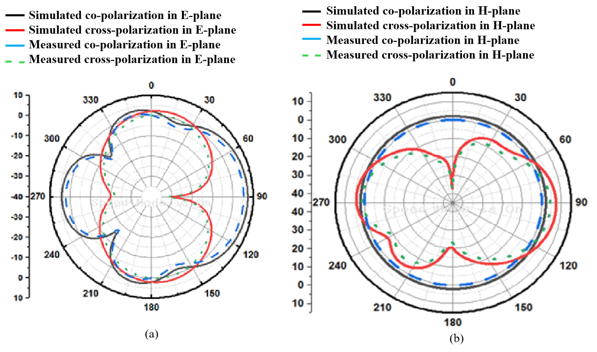
- The radiation pattern analysis reveals that the antenna provides an omnidirectional radiation pattern in both the E- and H-planes, making it suitable for various communication scenarios.
- The design’s compact structure and efficient performance across WLAN and X-band resonant bands (with bandwidth capacities of 500 MHz and 4300 MHz) make it highly advantageous for modern wireless communication and satellite applications.
2. Presented Antenna Structure
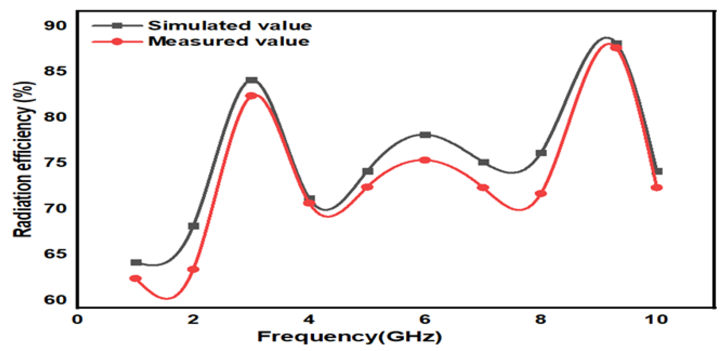
3. Results and Discussions
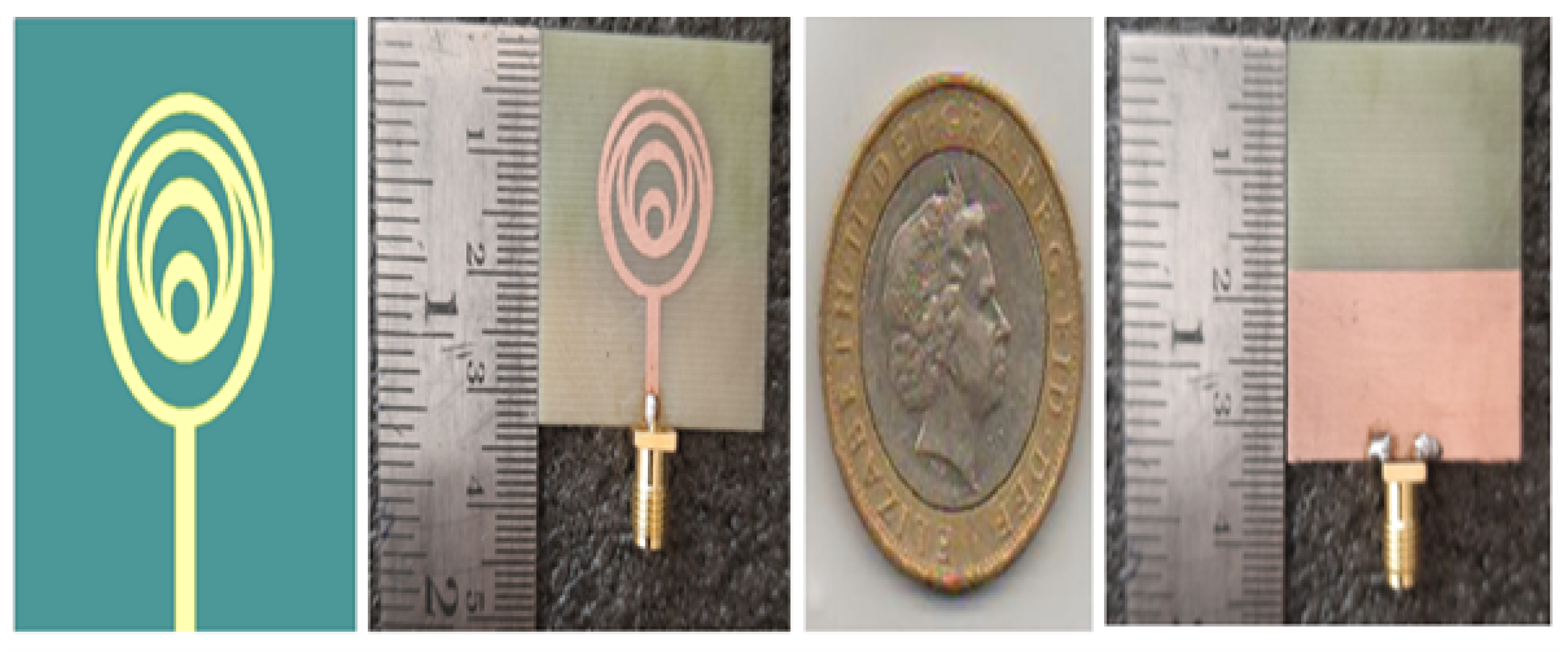
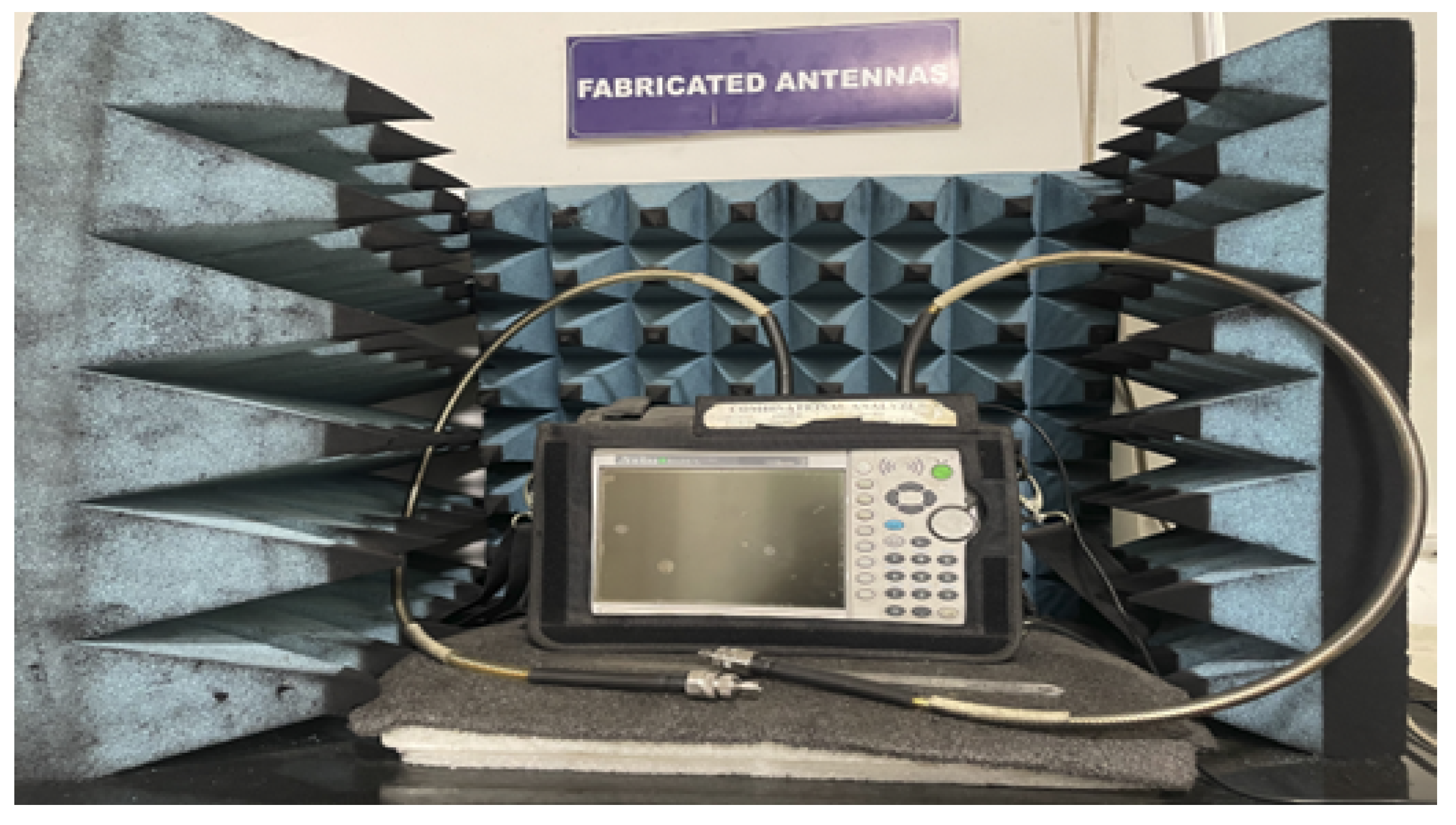
Fabricated Prototype
4. Conclusions and Future Research
Author Contributions
Funding
Data Availability Statement
Acknowledgments
Conflicts of Interest
References
- Jhamb, K.; Li, L.; Rambabu, K. Frequency adjustable microstrip annular ring patch antenna with multi-band characteristics. IET Microwaves Antennas Propag. 2011, 5, 1471–1478. [Google Scholar] [CrossRef]
- Nayna, T.F.; Baki, A.K.; Ahmed, F. Comparative study of rectangular and circular microstrip patch antennas in X band. In Proceedings of the 2014 International Conference Onelectrical Engineering and Information & Communication Technology, Dhaka, Bangladesh, 10–12 April 2014; pp. 1–5. [Google Scholar]
- Sharma, A.; Khanna, P.; Kumar, A.; Shinghal, K. A CPW-fed structure shaped substrate wideband microstrip antenna for wireless applications. J. Microwaves Optoelectron. Electromagn. Appl. 2017, 16, 419–433. [Google Scholar] [CrossRef]
- Mishra, R. An overview of microstrip antenna. HCTL Open Int. J. Technol. Innov. Res. (IJTIR) 2016, 21, 39–55. [Google Scholar]
- Lin, C.K.; Chung, S.J. A filtering microstrip antenna array. IEEE Trans. Microw. Theory Tech. 2011, 59, 2856–2863. [Google Scholar] [CrossRef]
- Saha, P.; Singh, A.; Pandey, V.K.; Kanaujia, B.K.; Khandelwal, M.K. Design and analysis of UWB circular ring two element microstrip patch antenna array with notched band for modern wireless applications. Microw. Opt. Technol. Lett. 2015, 57, 2067–2072. [Google Scholar] [CrossRef]
- Balanis, C.-A. Antenna Theory Analysis and Design; Wiley: NewYork, NY, USA, 1997. [Google Scholar]
- Xu, K.; Liu, Y.; Dong, L.; Peng, L.; Chen, S.; Shen, F.; Ye, X.; Chen, X.; Wang, G. Printed multi-band compound meta-loop antenna with hybrid-coupled SRRs. IET Microwaves Antennas Propag. 2018, 12, 1382–1388. [Google Scholar] [CrossRef]
- Khanna, P.; Shinghal, K.; Kumar, A. Multi-band annular ring microstrip antenna with defected ground structure for wireless communication. Int. J. Comput. Appl. 2016, 135, 19–25. [Google Scholar] [CrossRef]
- Ali, T.; Aw, M.S.; Biradar, R.C. A fractal quad-band antenna loaded with L-shaped slot and metamaterial for wireless applications. Int. J. Microw. Wirel. Technol. 2018, 10, 826–834. [Google Scholar] [CrossRef]
- Dhar, N.; Dutta, P.; Rahman, M.A.; Hossain, M.A.; Mobashsher, A.T. A design of a metamaterial integrated triple band antenna for wireless applications. In Proceedings of the TENCON 2019—2019 IEEE Region 10 Conference (TENCON), Kochi, India, 17–20 October 2019; pp. 209–213. [Google Scholar]
- Pedram, K.; Nourinia, J.; Ghobadi, C.; Pouyanfar, N.; Karamirad, M. Compact and miniaturized metamaterial-based microstrip fractal antenna with reconfigurable qualification. AEU-Int. J. Electron. Commun. 2020, 1, 152959. [Google Scholar] [CrossRef]
- Daniel, R.S.; Pandeeswari, R.; Raghavan, S. Offset-fed complementary split ring resonators loaded monopole antenna for multi-band operations. AEU-Int. J. Electron. Commun. 2017, 1, 72–78. [Google Scholar] [CrossRef]
- Rajkumar, R.; Kiran, K.U. A metamaterial inspired compact open split ring resonator antenna for multi-band operation. Wirel. Pers. Commun. 2017, 97, 951–965. [Google Scholar] [CrossRef]
- Zhang, Q.L.; Si, L.M.; Huang, Y.; Lv, X.; Zhu, W. Low-index-metamaterial for gain enhancement of planar terahertz antenna. AIP Adv. 2014, 4, 037103. [Google Scholar] [CrossRef]
- Ziolkowski, R.W.; Jin, P.; Lin, C.C. Metamaterial-inspired engineering of antennas. Proc. IEEE 2010, 99, 1720–1731. [Google Scholar] [CrossRef]
- Wang, L.; Yuan, M.Q.; Liu, Q.H. A dual-band printed electrically small antenna covered by two capacitive split-ring resonators. IEEE Antennas Wirel. Propag. Lett. 2011, 18, 824–826. [Google Scholar] [CrossRef]
- Daniel, R.S.; Pandeeswari, R.; Raghavan, S. Multiband monopole antenna loaded with Complementary Split Ring Resonator and C-shaped slots. AEU-Int. J. Electron. Commun. 2017, 1, 8–14. [Google Scholar] [CrossRef]
- Si, L.M.; Lv, X. CPW-fed multi-band omni-directional planar microstrip antenna using composite metamaterial resonators for wireless communications. Prog. Electromagn. Res. 2008, 83, 133–146. [Google Scholar] [CrossRef]
- Kubacki, R.; Czyzewski, M.; Laskowski, D. Minkowski island and crossbar fractal microstrip antennas for broadband applications. Appl. Sci. 2018, 8, 334. [Google Scholar] [CrossRef]
- Fukusako, T. Broadband characterization of circularly polarized waveguide antenna using L-shaped probe. J. Electromagn. Eng. Sci. 2017, 17, 1–8. [Google Scholar] [CrossRef]
- Hur, J.; Byun, G.; Choo, H. Design of small CRPA arrays with circular microstrip loops for electromagnetically coupled feed. J. Electromagn. Eng. Sci. 2018, 18, 129–135. [Google Scholar] [CrossRef]
- Trinh-Van, S.; Lee, J.M.; Yang, Y.; Lee, K.-Y.; Hwang, K.C. Improvement of RF wireless power transmission using a circularly polarized retrodirective antenna array with EBG structures. Appl. Sci. 2018, 8, 324. [Google Scholar] [CrossRef]
- Nelaturi, S.; Sarma, N.V.S.N. A compact microstrip patch antenna based on metamaterials for Wi-Fi and WiMAX applications. J. Electromagn. Eng. Sci. 2018, 18, 182–187. [Google Scholar] [CrossRef]
- Kweon, J.-H.; Park, M.-S.; Cho, J.; Jung, K.-Y. FDTD analysis of electromagnetic wave propagation in an inhomogeneous ionsphere under arbitrary-direction geomagnetic field. J. Electromagn. Eng. Sci. 2018, 18, 212–214. [Google Scholar] [CrossRef]
- Guo, L.; Tang, M.-C.; Li, M. A low-profile dual-layer patch antenna with a circular polarizer consiting of dual semicircular resonatores. Sensors 2018, 18, 1773. [Google Scholar] [CrossRef] [PubMed]
- Sze, J.-Y.; Wang, J.-C.; Chang, C.C. Axial-ratio bandwidth enhancement of asymmetric-CPW-fed circularly-polarised square slot antenna. Electron. Lett. 2008, 44, 1048–1049. [Google Scholar] [CrossRef]
- Deng, I.-C.; Cheng, J.-B.; Ke, Q.-X.; Chang, J.-R.; Chang, W.-F.; King, Y.-T.A. A circular CPW-fed slot antenna for broadband circularly polarized radiation. Microw. Opt. Technol. Lett. 2007, 49, 2728–2733. [Google Scholar] [CrossRef]
- Sze, J.-Y.; Hsu, C.-I.G.; Chen, Z.-W.; Chang, C.-C. Broadband CPW-fed circularly polarized square slot antenna with lightening-shaped feedline and inverted-L grounded strips. IEEE Trans. Antennas Propag. 2010, 58, 973–977. [Google Scholar] [CrossRef]
- Zhou, S.-W.; Li, P.-H.; Wang, Y.; Feng, W.-H.; Liu, Z.-Q. A CPW-fed broadband circularly polarized regular-hexagonal slot antenna with L-shape monopole. IEEE Antennas Wirel. Propag. Lett. 2011, 10, 1182–1185. [Google Scholar] [CrossRef]
- Li, G.; Zhai, H.; Li, T.; Li, L.; Liang, C. CPW-fed S-shaped slot antenna for broadband circular polarization. IEEE Antennas Wirel. Propag. Lett. 2013, 12, 619–622. [Google Scholar] [CrossRef]
- Li, G.; Zhai, H.; Li, L.; Liang, C. A nesting-L slot with enhanced circularly polarized bandwidth and radiation. IEEE Antennas Wirel. Propag. Lett. 2014, 13, 225–228. [Google Scholar] [CrossRef]
- Sze, J.-Y.; Chen, W.-H. Axial-ratio-bandwidth enhancement of a microstrip-line-fed circularly polarized annual-ring slot antenna. IEEE Trans. Antennas Propag. 2011, 59, 2450–2456. [Google Scholar] [CrossRef]
- Nasimuddin; Chen, Z.N.; Qing, X. Symmetric-aperture antenna for broadband circular polarization. IEEE Trans. Antennas Propag. 2011, 59, 3932–3936. [Google Scholar] [CrossRef]
- Le, T.T.; The, V.H.; Park, H.C. Simple and compact slot-patch antenna with broadband circularly polarized radiation. Microw. Opt. Technol. Lett. 2016, 58, 1634–1641. [Google Scholar]
- Samsuzzaman, M.; Islam, M.T. Circularly polarized broadband printed antenna for wireless applications. Sensors 2018, 18, 4261. [Google Scholar] [CrossRef] [PubMed]
- Saha, T.K.; Goodbody, C.; Karacolak, T.; Sekhar, P.K. A compact monopole antenna for ultra wideband applications. Microw. Opt. Technol. Lett. 2019, 61, 182–186. [Google Scholar] [CrossRef]
- Azim, R.; Islam, M.T.; Misran, N. Compact tapered-shape slot antenna for UWB applications. IEEE Antennas Wirel. Propag. Lett. 2011, 10, 1190–1193. [Google Scholar] [CrossRef]
- Kaushal, D.; Shanmuganantham, T.; Sajith, K. Dual band characteristics in a microstrip rectangular patch antenna using novel slotting technique. In Proceedings of the 2017 International Conference on Intelligent Computing, Instrumentation and Control Technologies (ICICICT), Kerala, India, 6–7 July 2017; pp. 957–960. [Google Scholar]
- Gharakhili, F.G.; Fardis, M.; Dadashzadeh, G.R.; Ahmadi, A.K.A.; Hojjat, N. Circular slot with a novel circular microstrip open ended microstrip feed for UWB applications. Prog. Electromagn. Res. 2007, 68, 161–167. [Google Scholar] [CrossRef]
- Liang, J.; Chiau, C.; Chen, X.; Parini, C. Printed circular disc monopole antenna for ultra-wideband applications. Electron. Lett. 2004, 40, 1246–1247. [Google Scholar] [CrossRef]
- Abedian, M.; Rahim, S.; Danesh, S.; Khalily, M.; Noghabaei, S. Ultrawideband dielectric resonator antenna with WLAN band rejection at 5.8 GHz. IEEE Antennas Wirel. Propag. Lett. 2013, 12, 1523–1526. [Google Scholar] [CrossRef]
- Gatea, K.M. Compact ultra wideband circular patch microstrip antenna. In Proceedings of the 2012 Frst National Conference for Engineering Sciences (FNCES 2012), Baghdad, Iraq, 7–8 November 2012; pp. 1–5. [Google Scholar]
- Kadam, A.A.; Deshmukh, A.A.; Deshmukh, S.; Doshi, A.; Ray, K.P. Slit loaded circular ultra wideband antenna for band notch characteristics. In Proceedings of the 2019 National Conference on Communications (NCC), Bangalore, India, 20–23 February 2019; pp. 1–6. [Google Scholar]
- Karamanoğlu, M.; Abbak, M.; Şimşek, S. A planar ultra-wideband monopole antenna with half-circular parasitic patches. In Proceedings of the 2013 13th Mediterranean Microwave Aymposium (MMS), Saida, Lebanon, 2–5 September 2013; pp. 1–4. [Google Scholar]
- Kumar, N.; Singh, K.K.; Badhai, R.K. A tapered feed circular monopole super ultra-wideband (UWB) printed antenna. In Proceedings of the 2016 International Conference on Communication and Signal Processing (ICCSP), Melmaruvathur, India, 6–8 April 2016; pp. 1943–1946. [Google Scholar]
- Sayidmarie, K.H.; Fadhel, Y.A. Design aspects of UWB printed elliptical monopole antenna with impedance matching. In Proceedings of the 2012 Loughborough Antennas & Propagation Conference (LAPC), Loughborough, UK, 12–13 November 2012; pp. 1–4. [Google Scholar]
- Nayna, T.F.A.; Haque, E.; Ahmed, F. Design of a X band defected ground circular patch antenna with diamond shaped slot and ring in patch for UWB applications. In Proceedings of the 2016 International Conference on Signal Processing, Communication, Power and Embedded System (SCOPES), Paralakhemundi, India, 3–5 October 2016; pp. 559–562. [Google Scholar]
- Mishra, S.K.; Gupta, R.K.; Vaidya, A.; Mukherjee, J. A compact dual-band fork-shaped monopole antenna for Bluetooth and UWB applications. IEEE Antennas Wirel. Propag. Lett. 2011, 10, 627–630. [Google Scholar] [CrossRef]
- Lu, J.-H.; Yeh, C.-H. Planar broadband arc-shaped monopole antenna for UWB system. IEEE Trans. Antennas Propag. 2012, 60, 3091–3095. [Google Scholar] [CrossRef]
- Rao, P.K.; Singh, K.J.; Mishra, R. A circular shaped microstrip patch antenna for bluetooth/Wi-Fi/UWB/X-band applications. In Proceedings of the 2018 International Conference on Power Energy, Environment and Intelligent Control (PEEIC), Greater Noida, India, 13–14 April 2018; pp. 638–641. [Google Scholar]
- Rodrigues, E.J.; Lins, H.W.; D’Assunção, A.G. Reconfgurable circular ring patch antenna for UWB and cognitive radio applications. In Proceedings of the The 8th European Conference on Antennas and Propagation (EuCAP 2014), The Hague, The Netherlands, 6–11 April 2014; pp. 2744–2748. [Google Scholar]
- Safa, O.A.; Omar, A.; Nedil, M. CPW-fed UWB antenna based on packing congruent circles in a circular patch. In Proceedings of the 2016 5th International Conference on Electronic Devices, Systems and Applications (ICEDSA), Ras Al Khaimah, United Arab Emirates, 6–8 December 2016; pp. 1–3. [Google Scholar]
- Zainud-Deen, S.H.; El-Shalaby, N.A.; Malhat, H.A.; Gaber, S.M. Reconfigurable multi-turns planar plasma helical antenna. Plasmonics 2019, 14, 1831–1837. [Google Scholar] [CrossRef]
- Shamim, S.M.; Dina, U.S.; Arafin, N.; Sultana, S. Design of efficient 37 GHz millimeter wave microstrip patch antenna for 5G mobile application. Plasmonics 2021, 16, 1417–1425. [Google Scholar] [CrossRef]
- Babu, G.H.; Srinivas, M.; Gnanaprakasam, C.; Prabu, R.T.; Devi, M.R.; Ahammad, S.H.; Hossain, M.A.; Rashed, A.N.Z. Meander Line Base Asymmetric Co-planar Wave Guide (CPW) Feed Tri-Mode Antenna for Wi-MAX, North American Public Safety and Satellite Applications. Plasmonics 2023, 18, 1007–1018. [Google Scholar] [CrossRef]
- Govardhani, I.; Narayana, M.V.; Navya, A.; Venkatesh, A.; Spurjeon, S.C.; Venkat, S.S.; Sanjay, S. Design of high directional crossed dipole antenna with metallic sheets for UHF and VHF applications. Int. J. Eng. Technol. (UAE) 2018, 7, 42–50. [Google Scholar] [CrossRef]
- Imamdi, G.; Narayan, M.V.; Navya, A.; Roja, A. Reflector array antenna design at millimetric (mm) band for on the move applications. ARPN J. Eng. Appl. Sci. 2018, 13, 352–359. [Google Scholar]
- Immadi, G.; Narayana, M.V.; Navya, A.; Varma, C.A.; Reddy, A.A.; Deepika, A.M.; Kavya, K. Analysis of substrate integrated frequency selective surface antenna for iot applications. Indones. J. Electr. Eng. Comput. Sci. 2020, 18, 875–881. [Google Scholar]
- Kumar, M.N.; Narayana, M.V.; Immadi, G.; Satyanarayana, P.; Navya, A. Analysis of a low-profile, dual band patch antenna for wireless applications. AIMS Electron. Electr. Eng. 2023, 7, 171–186. [Google Scholar] [CrossRef]
- Reddy, K.H.; Narayana, M.V.; Immadi, G.; Satyanarayana, P.; Rajkamal, K.; Navya, A. A Low-Profile Electrically Small Antenna with a Circular Slot for Global Positioning System Applications. Prog. Electromagn. Res. C 2023, 133, 27–38. [Google Scholar] [CrossRef]


| Parameters | Dimensions (mm) |
|---|---|
| L1 | 35 |
| L2 | 2 |
| W1 | 33 |
| W2 | 15 |
| r | 8 |
| a | 1 |
| b | 1.5 |
| c | 2 |
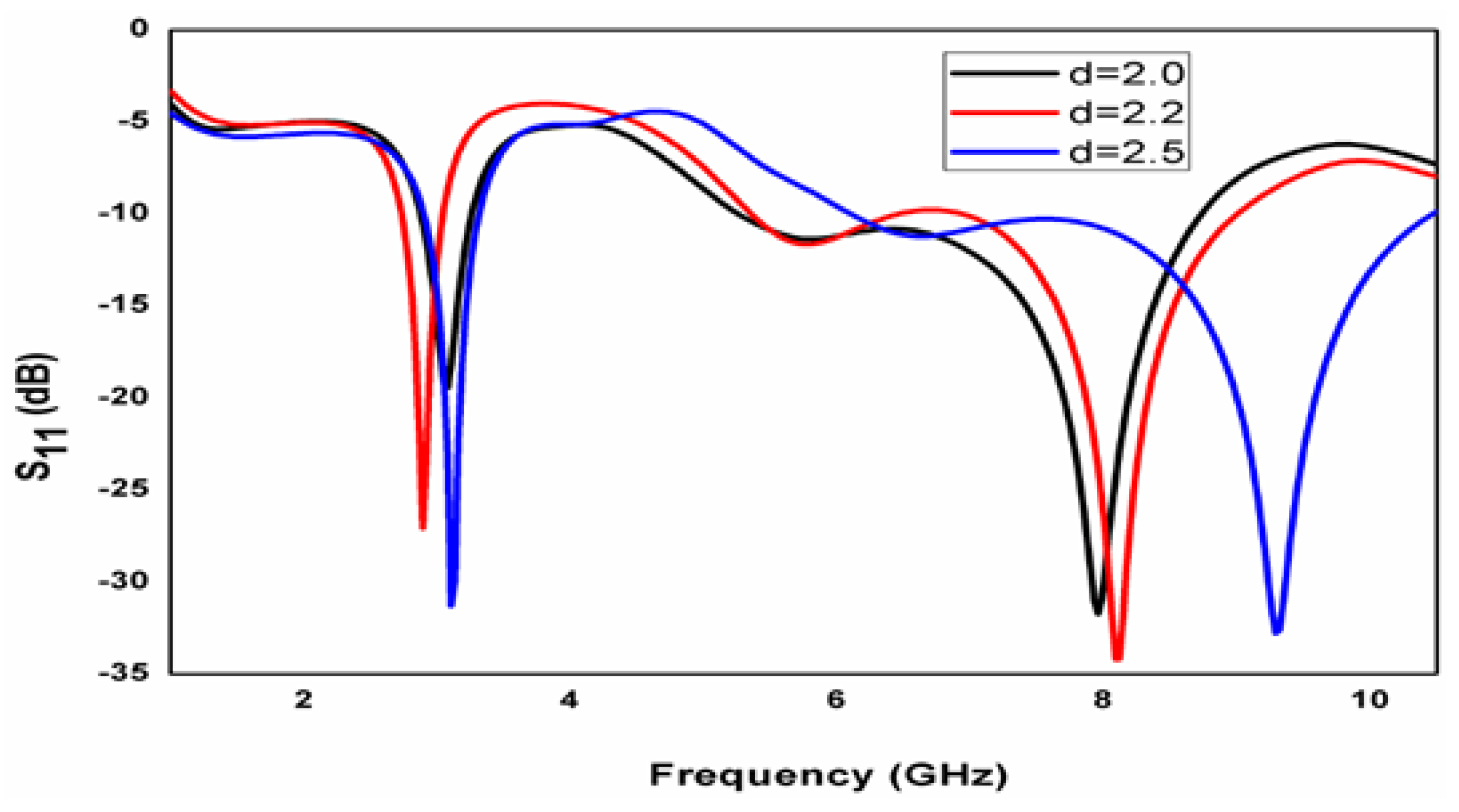
| d | 2.5 |
| Antenna | Frequency (GHz) | Gain (dBi) |
|---|---|---|
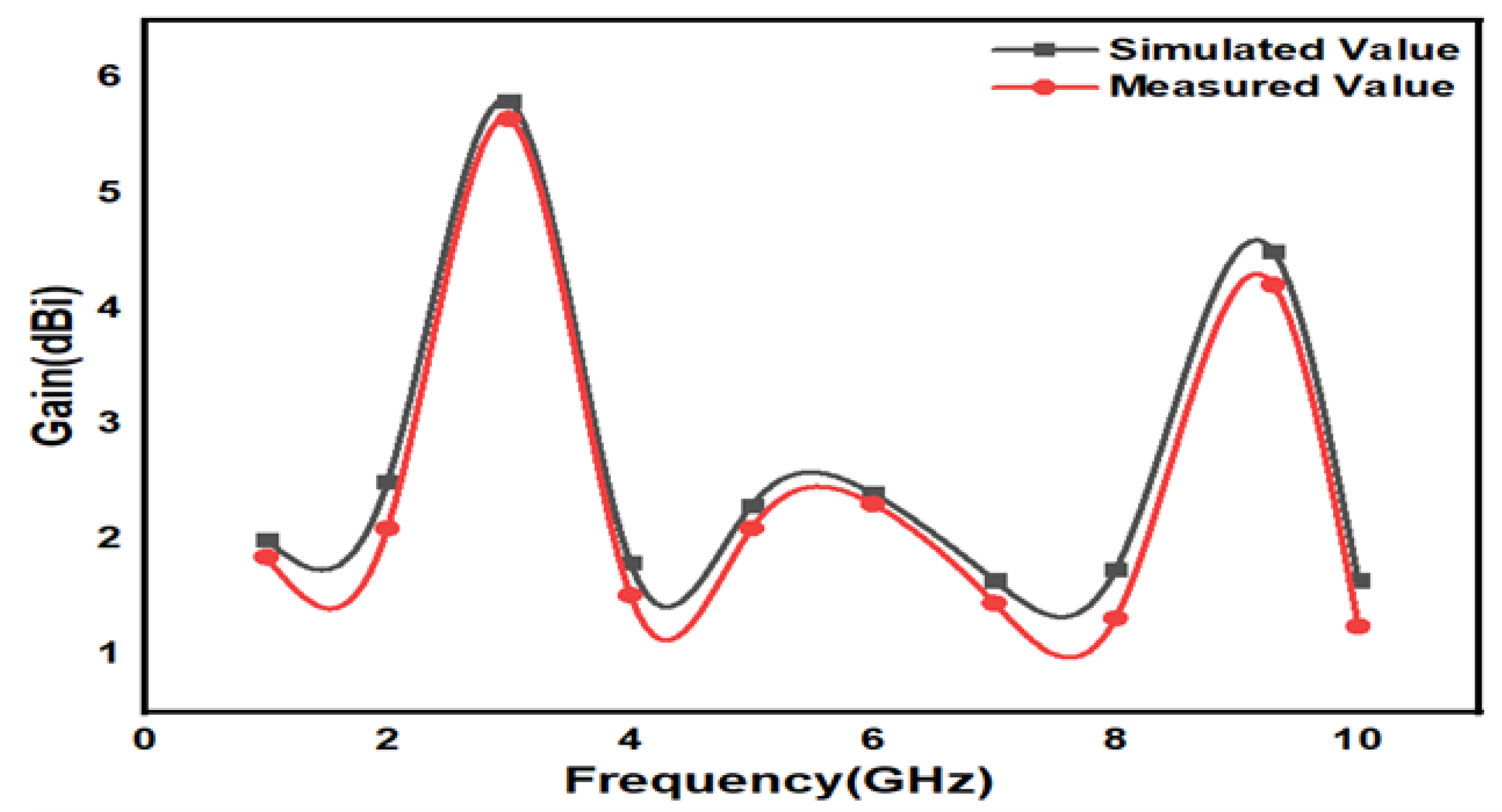
| Simulated | 3.1/9.3 | 5.8/4.5 |
| Measured | 3.15/9.38 | 6.1/5.4 |
| Antenna | Frequency (GHz) | Return Loss (dB) | Bandwidth (MHz) |
|---|---|---|---|
| Simulated | 3.1/9.3 | −33/−32 | 500/4800 |
| Measured | 3.15/9.38 | −22/−24 | 400/4400 |
| References | Dimensions (mm2) | Operating Bands (GHz) | Peak Gain (dBi) | Substrate Material | Design Complexity |
|---|---|---|---|---|---|
| [54] | 100 × 60 × 1.6 | 2.17–2.72 3.34–3.66 4.85–5.77 | 3.75 3.56 3.93 | FR4 4.2 | Moderate |
| [55] | 30 × 65 × 1.6 | 2.375–2.525 3.075–3.80 5.00–6.90 | 1.30 5.20 3.10 | FR4 4.3 | Moderate |
| [56] | 40 × 45 × 1.6 | 2.02–2.14 4.26–4.28 5.45–5.56 | 1.87 2.90 4.13 | FR4 4.4 | Complex |
| [57] | 33 × 50.9 × 1.6 | 2.80–3.00 3.30–3.50 3.80–8.00 | 2.32 1.21 −6.00 | FR4 4.4 | Moderate |
| [58] | 40 × 40 × 1.6 | 2.20–2.50 4.00–4.20 6.70–8.10 | NR | FR4 4.4 | Complex |
| Proposed work | 35 × 33 × 1.6 | 2.8–3.2 6.16–10.45 | 5.8–4.5 | FR4 4.4 | Moderate |
Disclaimer/Publisher’s Note: The statements, opinions and data contained in all publications are solely those of the individual author(s) and contributor(s) and not of MDPI and/or the editor(s). MDPI and/or the editor(s) disclaim responsibility for any injury to people or property resulting from any ideas, methods, instructions or products referred to in the content. |
© 2024 by the authors. Licensee MDPI, Basel, Switzerland. This article is an open access article distributed under the terms and conditions of the Creative Commons Attribution (CC BY) license (https://creativecommons.org/licenses/by/4.0/).
Share and Cite
Aras, U.; Delwar, T.S.; Durgaprasadarao, P.; Sundar, P.S.; Ahammad, S.H.; Eid, M.M.A.; Lee, Y.; Zaki Rashed, A.N.; Ryu, J.-Y. Dual Features, Compact Dimensions and X-Band Applications for the Design and Fabrication of Annular Circular Ring-Based Crescent-Moon-Shaped Microstrip Patch Antenna. Micromachines 2024, 15, 809. https://doi.org/10.3390/mi15070809
Aras U, Delwar TS, Durgaprasadarao P, Sundar PS, Ahammad SH, Eid MMA, Lee Y, Zaki Rashed AN, Ryu J-Y. Dual Features, Compact Dimensions and X-Band Applications for the Design and Fabrication of Annular Circular Ring-Based Crescent-Moon-Shaped Microstrip Patch Antenna. Micromachines. 2024; 15(7):809. https://doi.org/10.3390/mi15070809
Chicago/Turabian StyleAras, Unal, Tahesin Samira Delwar, P. Durgaprasadarao, P. Syam Sundar, Shaik Hasane Ahammad, Mahmoud M. A. Eid, Yangwon Lee, Ahmed Nabih Zaki Rashed, and Jee-Youl Ryu. 2024. "Dual Features, Compact Dimensions and X-Band Applications for the Design and Fabrication of Annular Circular Ring-Based Crescent-Moon-Shaped Microstrip Patch Antenna" Micromachines 15, no. 7: 809. https://doi.org/10.3390/mi15070809