
A Novel Device for Micro-Droplets Generation Based on the Stepwise Membrane Emulsification Principle

Abstract
:1. Introduction
2. Materials and Methods
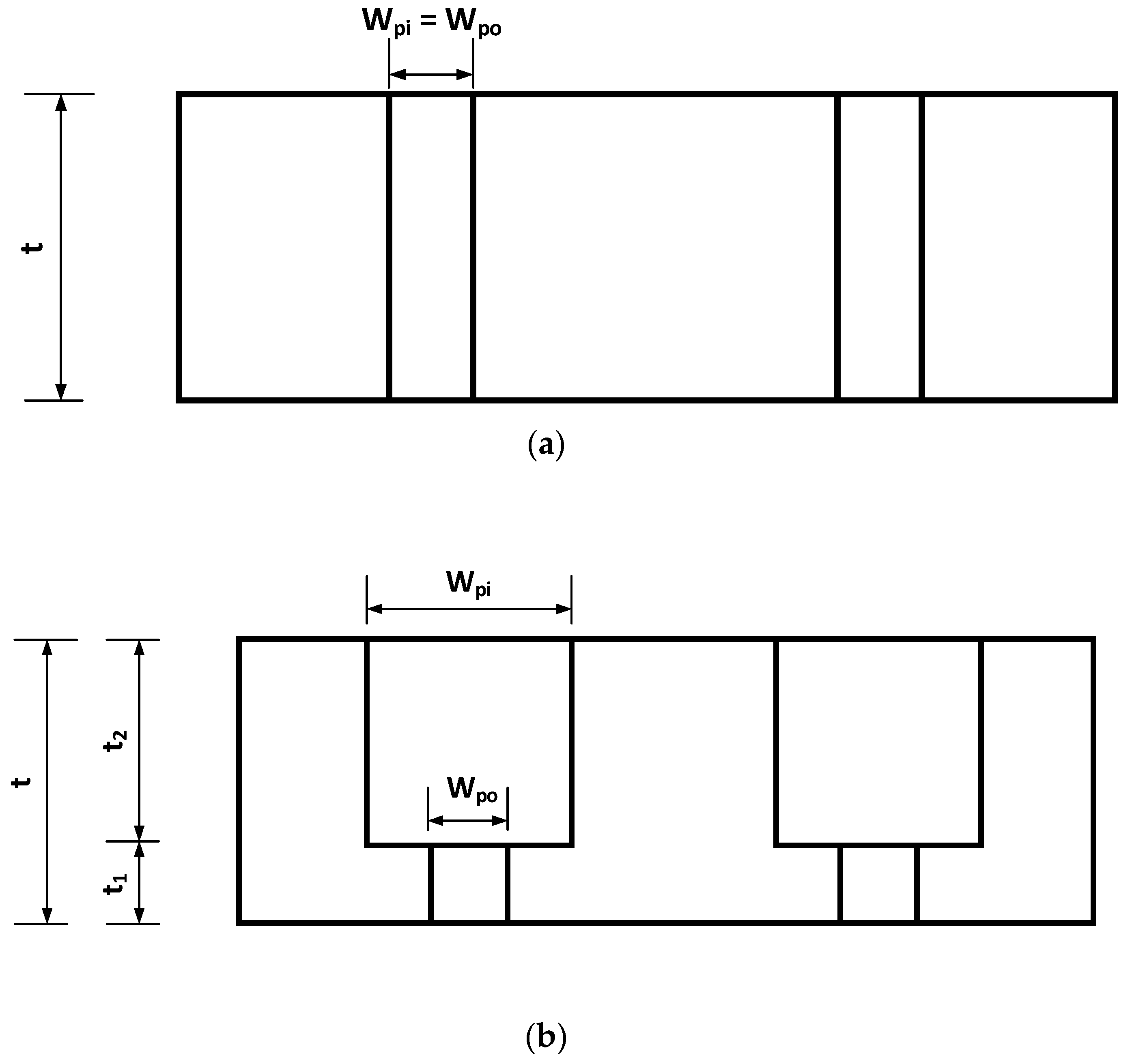
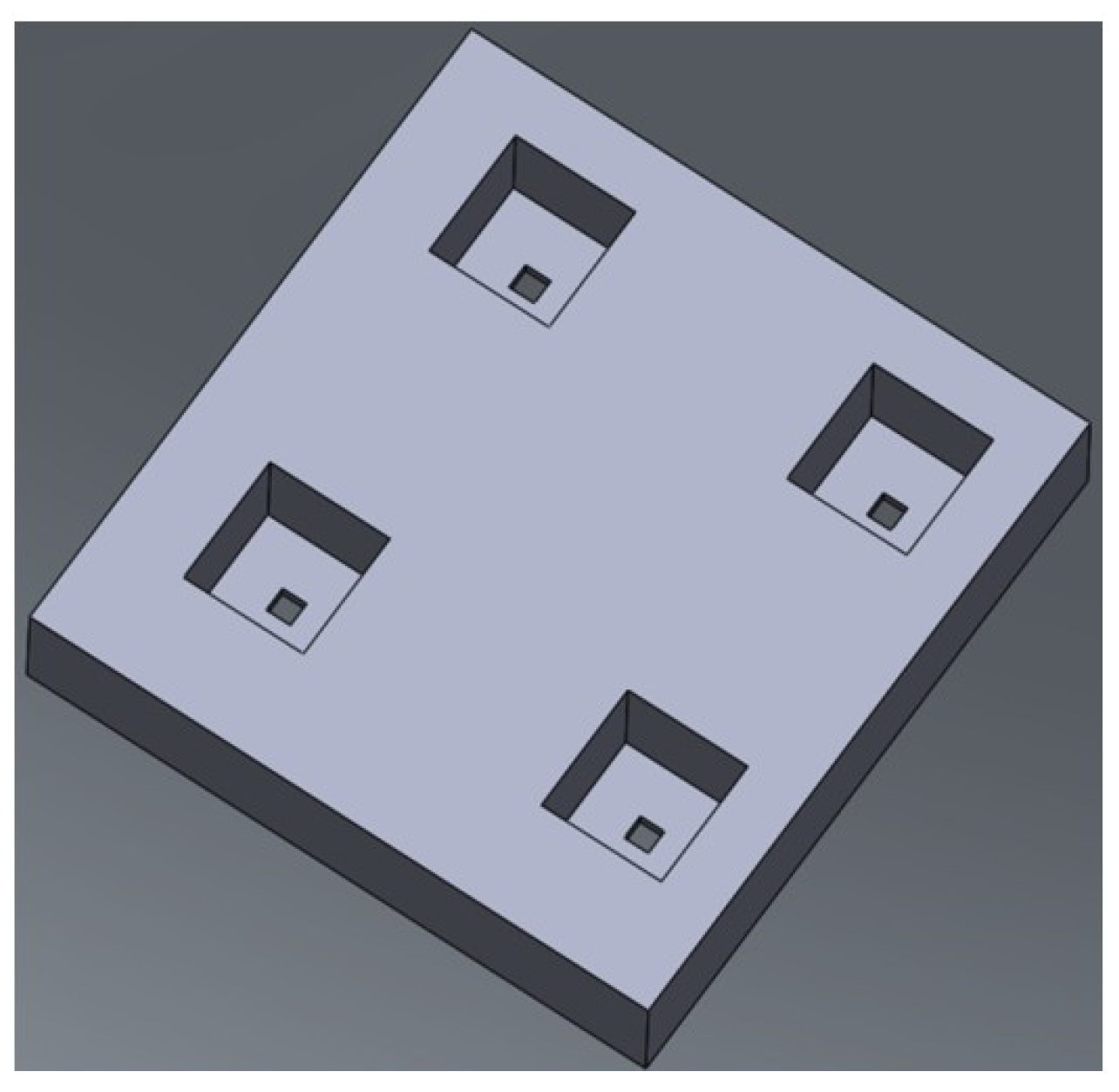
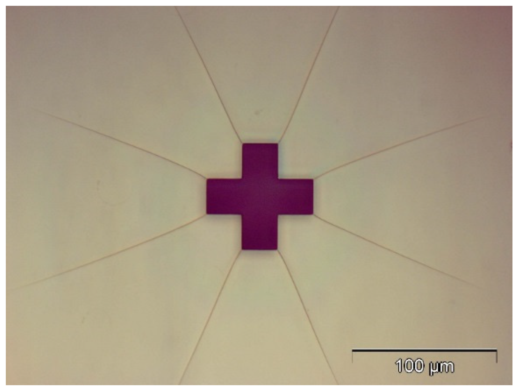
2.1. Design
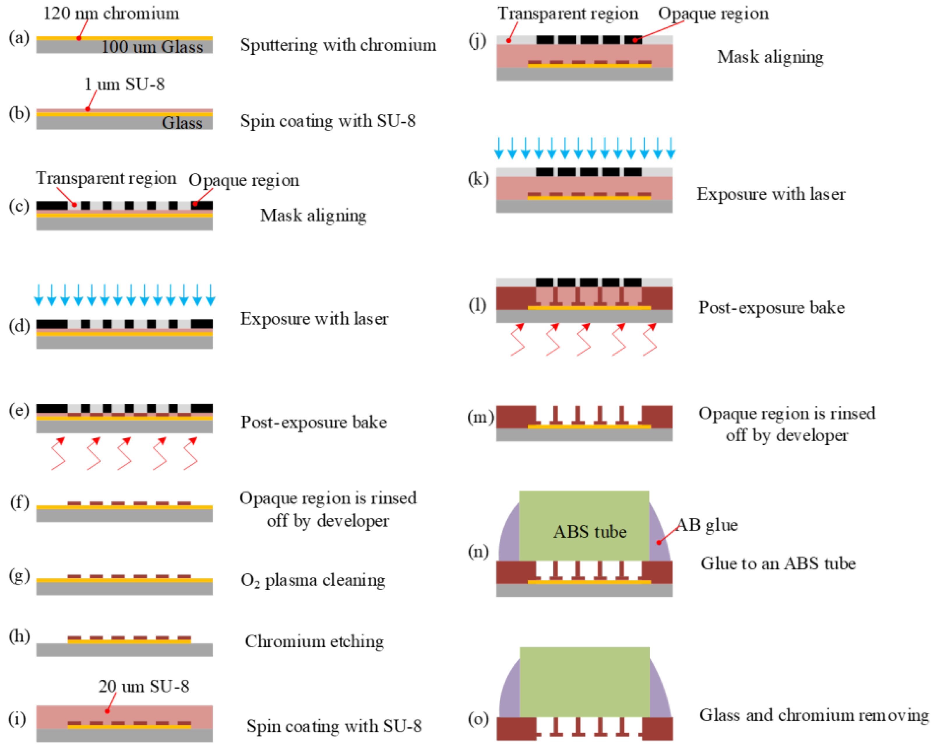
2.2. Fabrication
2.2.1. Chromium Sputtering
2.2.2. SU-8 Spin Coating (1 μm)
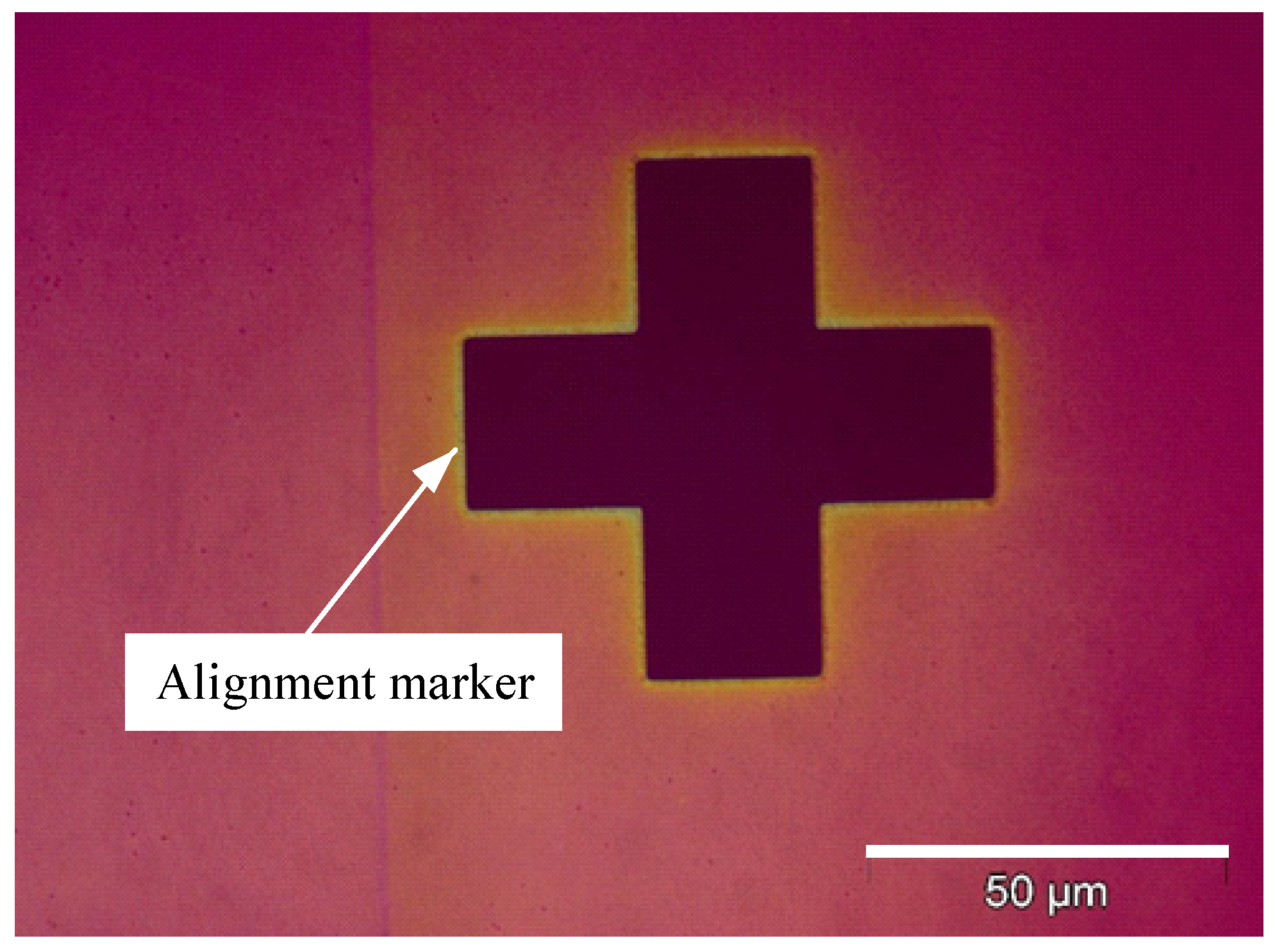
2.2.3. Mark Alignment
2.2.4. Exposure
2.2.5. Post-Exposure Bake (PEB)
2.2.6. Development
2.2.7. Oxygen Descum Plasma Cleaning
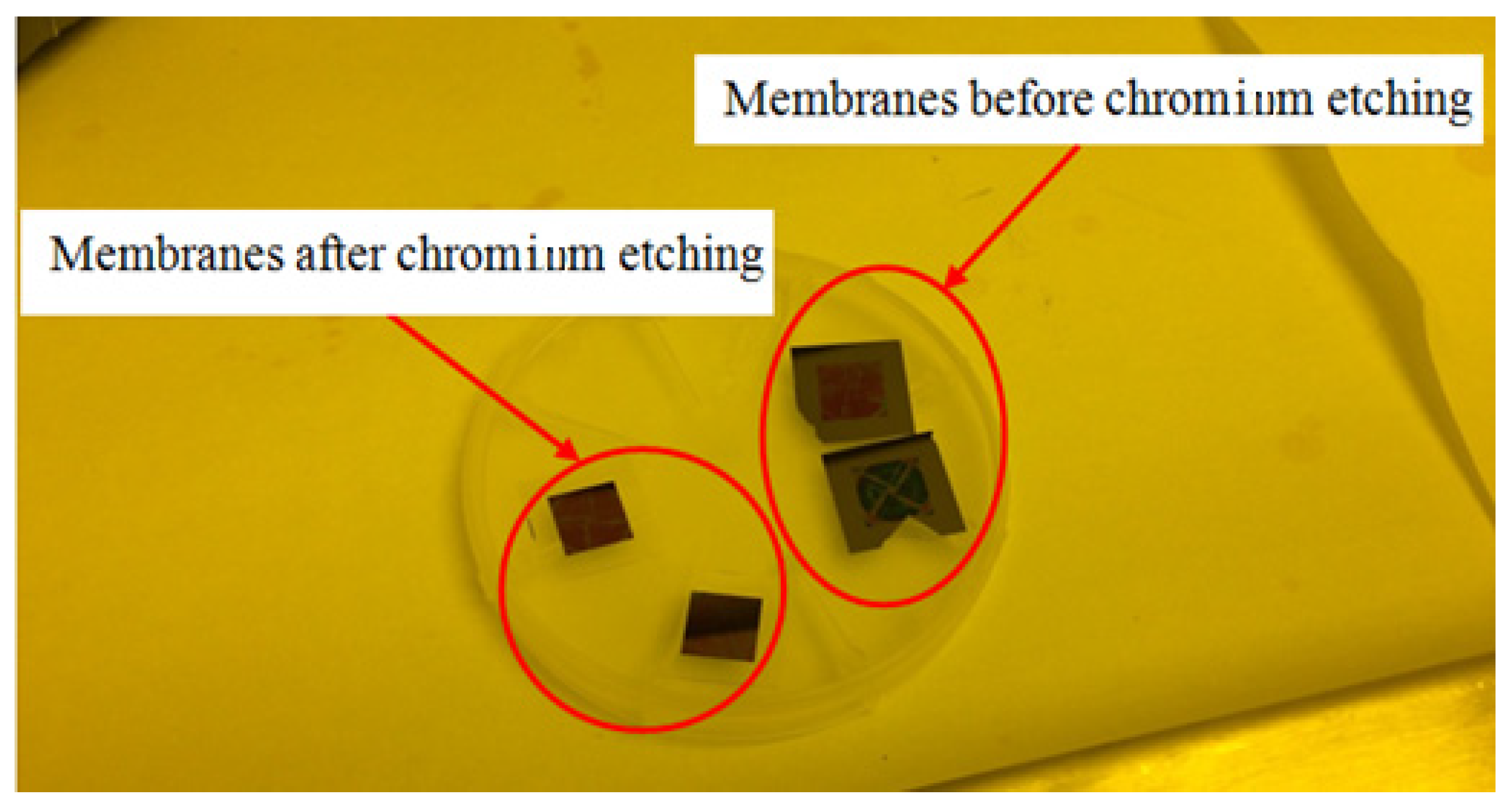
2.2.8. Chromium Etching
2.2.9. SU-8 Spin Coating (20 μm)
2.2.10. Mark Alignment
2.2.11. Exposure
2.2.12. Post-Exposure Bake (PEB)
2.2.13. Development
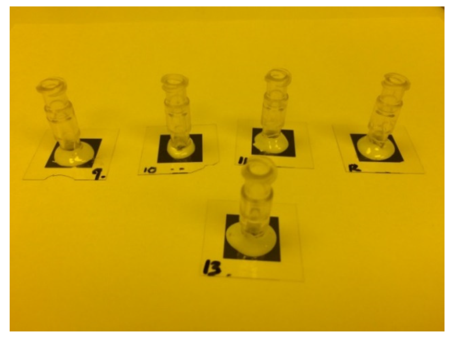
2.2.14. Glued to an Acrylonitrile Butadiene Styrene (ABS) Tube
2.2.15. Substrate and Chromium Removing
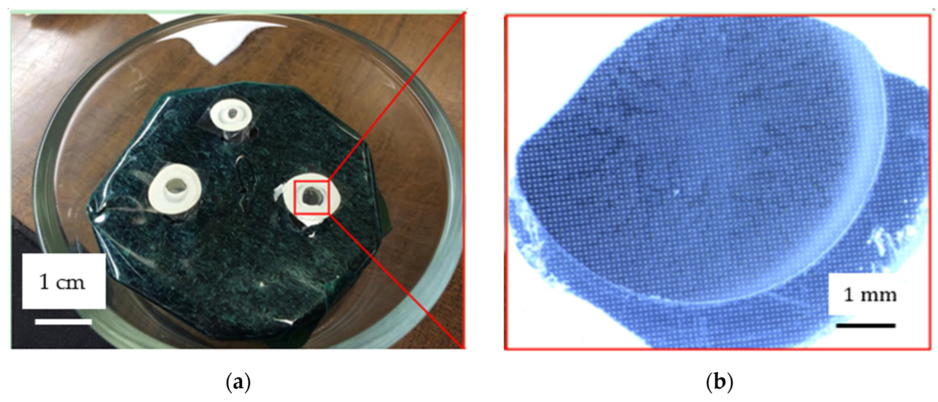
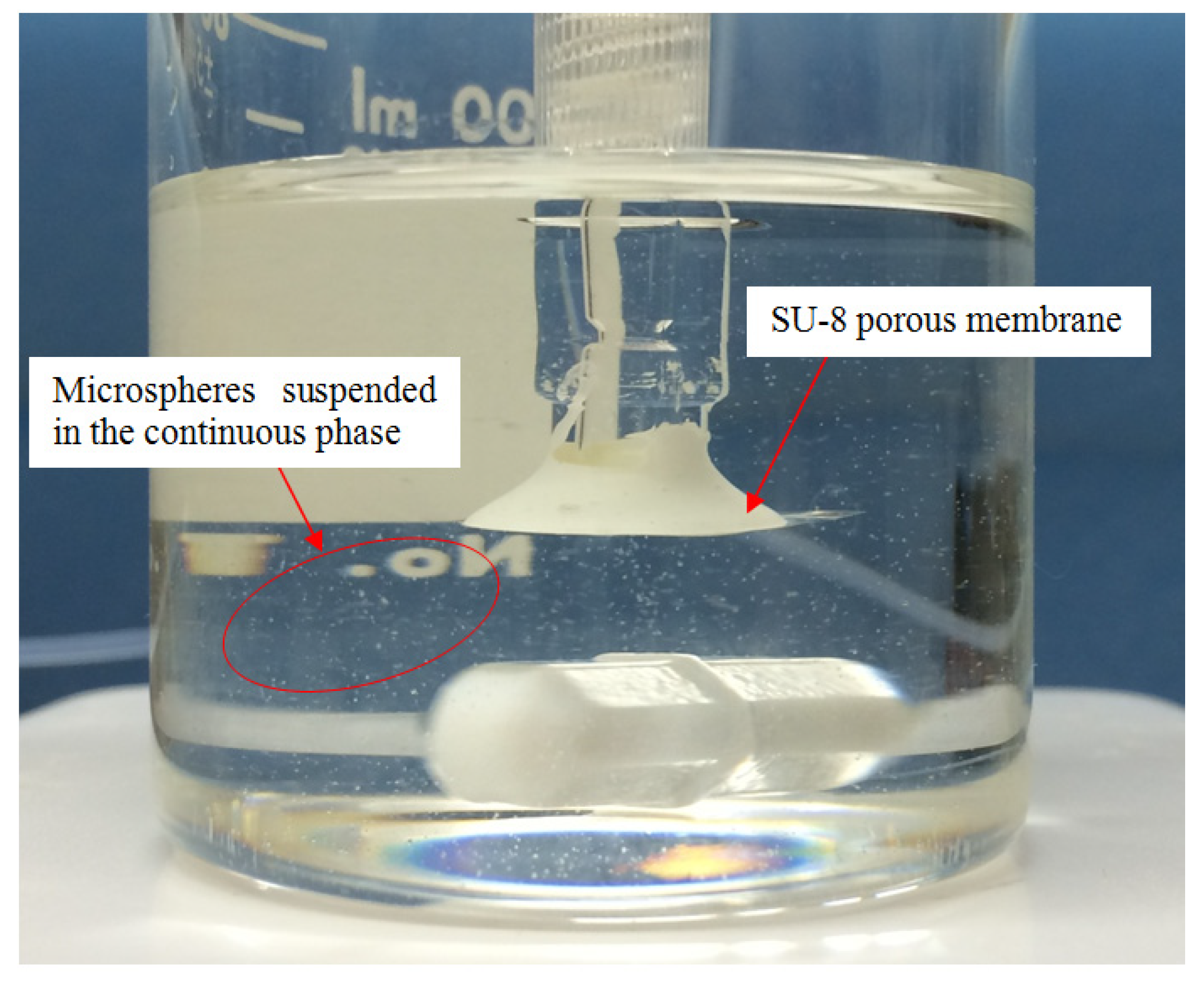
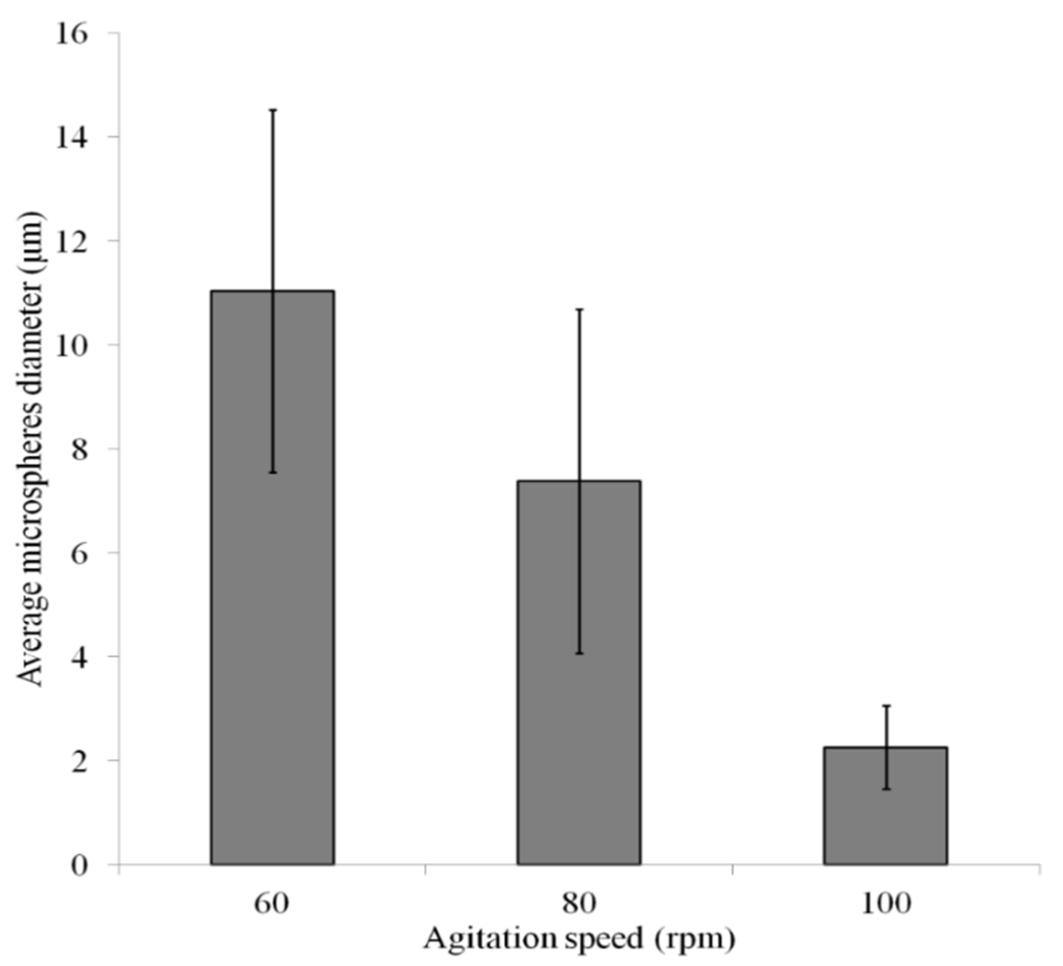
2.3. Experiment
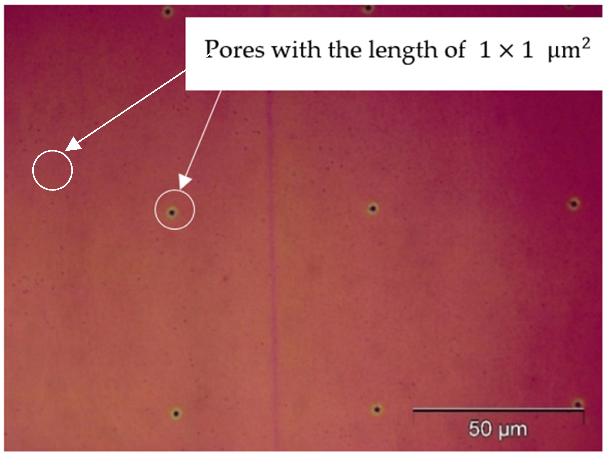
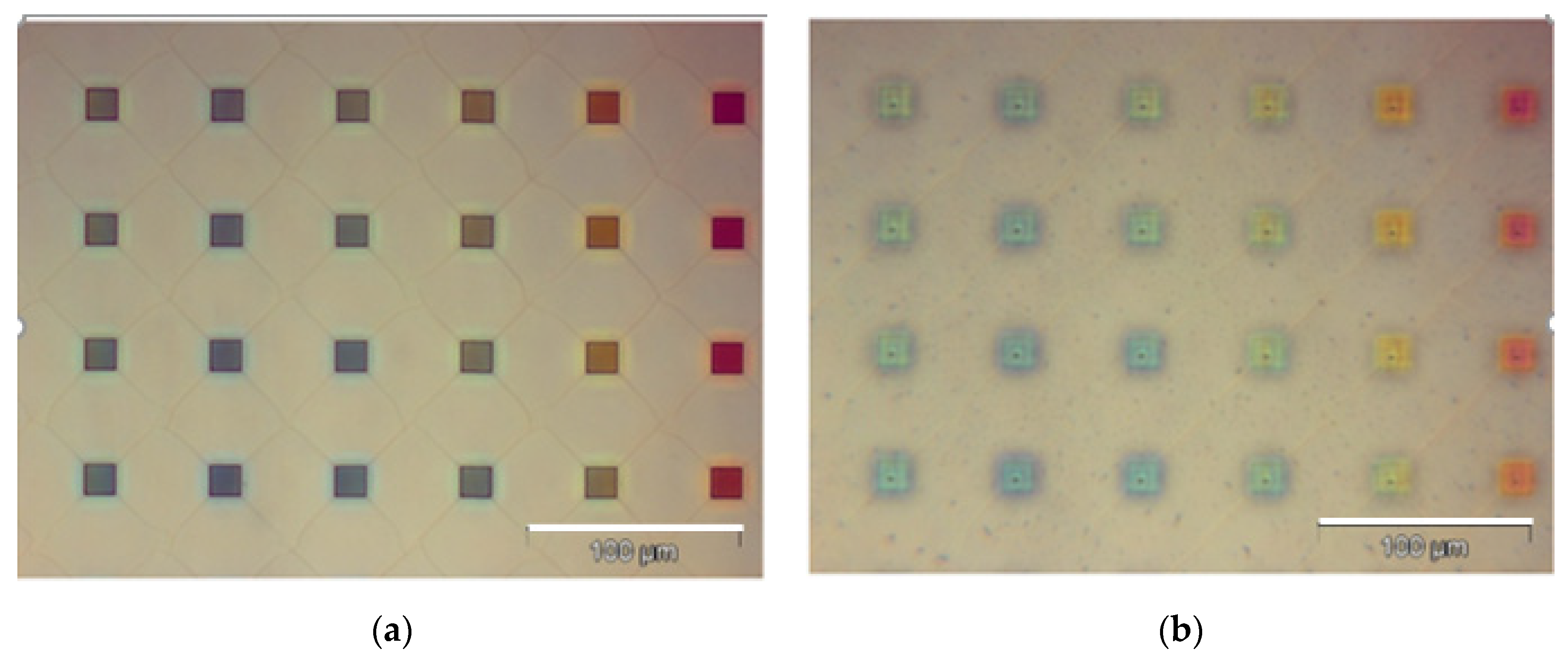
3. Results with Discussion
4. Conclusions and Future Work
Author Contributions
Funding
Data Availability Statement
Acknowledgments
Conflicts of Interest
Nomenclatures
| SPG | Shirasu Porous Glass |
| t1 | thickness of the bottom layer |
| t2 | thickness of the upper layer |
| wpi | size of the square pore for the upper layer |
| wpo | size of the square pore for the bottom layer |
| rpm | revolutions per minute |
| s | second |
| min | minute |
| h | hour |
| PEB | post-exposure bake |
| PGMEA | propylene glycol methyl ether acetate |
| IPA | isopropyl alcohol |
| nitrogen | |
| DI | distilled water |
| ABS | acrylonitrile butadiene styrene |
| HF | hydrofluoric |
| minimum pressure that ensures the dispersed phase can be pressed through the porous membrane | |
| interfacial tension between the continuous and dispersed phases | |
| the contact angle between the dispersed phase and the membrane surface in the continuous phase | |
| pore diameter |
References
- Zhu, J.; Wang, M.; Zhang, H.; Yang, S.; Song, K.-Y.; Yin, R.; Zhang, W. Effects of Hydrophilicity, Adhesion Work, and Fluid Flow on Biofilm Formation of PDMS in Microfluidic Systems. ACS Appl. Bio Mater. 2020, 3, 8386–8394. [Google Scholar] [CrossRef]
- Yin, R.; He, J.; Bai, M.; Huang, C.; Wang, K.; Zhang, H.; Yang, S.-M.; Zhang, W. Engineering synthetic artificial pancreas using chitosan hydrogels integrated with glucose-responsive microspheres for insulin delivery. Mater. Sci. Eng. C-Mater. Biol. Appl. 2019, 96, 374–382. [Google Scholar] [CrossRef] [PubMed]
- Gholamipour-Shirazi, A.; Carvalho, M.S.; Fossum, J.O. Controlled microfluidic emulsification of oil in a clay nanofluid: Role of salt for Pickering stabilization. Eur. Phys. J.-Spec. Top. 2016, 225, 757–765. [Google Scholar] [CrossRef]
- Perez-Moral, N.; Watt, S.; Wilde, P. Comparative study of the stability of multiple emulsions containing a gelled or aqueous internal phase. Food Hydrocoll. 2014, 42, 215–222. [Google Scholar] [CrossRef]
- Santos, J.; Arriaga, L.R.; Calero, N.; Lee, H.; Munoz, J.; David, D.A. Influence of the formulation on double emulsions containing ecological ingredients prepared by a microfluidic technique. Afinidad 2018, 75, 182–188. [Google Scholar]
- Yin, R.; Wang, K.; Du, S.; Chen, L.; Nie, J.; Zhang, W. Design of genipin-crosslinked microgels from concanavalin A and glucosyloxyethyl acrylated chitosan for glucose-responsive insulin delivery. Carbohydr. Polym. 2014, 103, 369–376. [Google Scholar] [CrossRef]
- Yin, D.; Zhang, H.; Yang, C.; Zhang, W.; Yang, S. A More Biomimetic Cell Migration Assay with High Reliability and Its Applications. Pharmaceuticals 2022, 15, 695. [Google Scholar] [CrossRef]
- Sugiyama, H.; Osaki, T.; Takeuchi, S.; Toyota, T. Perfusion Chamber for Observing a Liposome-Based Cell Model Prepared by a Water-in-Oil Emulsion Transfer Method. ACS Omega 2020, 5, 19429–19436. [Google Scholar] [CrossRef]
- Farahinia, A.; Zhang, W.J.; Badea, I. Novel microfluidic approaches to circulating tumor cell separation and sorting of blood cells: A review. J. Sci.-Adv. Mater. Devices 2021, 6, 303–320. [Google Scholar] [CrossRef]
- Jia, Y.H.; Zhang, H.B.; Yang, S.B.; Xi, Z.H.; Tang, T.T.; Yin, R.X.; Zhang, W.J. Electrospun PLGA membrane incorporated with andrographolide-loaded mesoporous silica nanoparticles for sustained antibacterial wound dressing. Nanomedicine 2018, 13, 2881–2899. [Google Scholar] [CrossRef] [PubMed]
- Yang, C.; Yin, D.; Zhang, H.B.; Badea, I.; Yang, S.M.; Zhang, W.J. Cell Migration Assays and Their Application to Wound Healing Assays—A Critical Review. Micromachines 2024, 15, 720. [Google Scholar] [CrossRef]
- Farahinia, A.; Zhang, W.; Badea, I. Recent Developments in Inertial and Centrifugal Microfluidic Systems along with the Involved Forces for Cancer Cell Separation: A Review. Sensors 2023, 23, 5300. [Google Scholar] [CrossRef]
- Lei, L.; Bergstrom, D.J.; Zhang, B.; Zhang, H.; Yin, R.; Song, K.Y.; Zhang, W. Micro/Nanospheres Generation by Fluid-Fluid Interaction Technology: A Literature Review. Recent Pat. Nanotechnol. 2017, 11, 15–33. [Google Scholar] [CrossRef] [PubMed]
- Wu, J.; Yadavali, S.; Lee, D.; Issadore, D.A. Scaling up the throughput of microfluidic droplet-based materials synthesis: A review of recent progress and outlook. Appl. Phys. Rev. 2021, 8, 031304. [Google Scholar] [CrossRef]
- Chattopadhyay, A.K.; Mittal, K.L. Surfactants in Solution; CRC Press: Boca Raton, FL, USA, 2020. [Google Scholar]
- Solans, C.; Morales, D.; Homs, M. Spontaneous emulsification. Curr. Opin. Colloid Interface Sci. 2016, 22, 88–93. [Google Scholar] [CrossRef]
- Nakashima, T.; Shimizu, M. Porous glass from calcium alumino boro-silicate glass. Bull. Ceram. Soc. Jpn. 1986, 21, 408–412. [Google Scholar]
- Charcosset, C.; Limayem, I.; Fessi, H. The membrane emulsification process—A review. J. Chem. Technol. Biotechnol. Int. Res. Process Environ. Clean Technol. 2010, 79, 209–218. [Google Scholar] [CrossRef]
- Lei, L. Modeling and Optimization of the Microsphere Generation. Ph.D. Thesis, University of Saskatchewan, Saskatoon, SK, Canada, 2016. [Google Scholar]
- Song, K.Y. Design and Fabrication of Novel Microfluidic Systems for Microsphere Generation. Ph.D. Thesis, University of Saskatchewan, Saskatoon, SK, Canada, 2011. [Google Scholar]
- Reis, D.R.; Zin, G.; Lemos-Senna, E.; Ambrosi, A.; Di Luccio, M. A modified premix method for the emulsification of spearmint essential oil (Mentha spicata) by ceramic membranes. Surf. Interfaces 2021, 26, 101328. [Google Scholar] [CrossRef]
- Othman, R.; Vladisavljevic, G.T.; Nagy, Z.K.; Holdich, R.G. Encapsulation and Controlled Release of Rapamycin from Polycaprolactone Nanoparticles Prepared by Membrane Micromixing Combined with Antisolvent Precipitation. Langmuir 2016, 32, 10685–10693. [Google Scholar] [CrossRef]
- Laouini, A.; Jaafar-Maalej, C.; Sfar, S.; Charcosset, C.; Fessi, H. Liposome preparation using a hollow fiber membrane contactor-Application to spironolactone encapsulation. Int. J. Pharm. 2011, 415, 53–61. [Google Scholar] [CrossRef]
- Madou, M.J. Fundamentals of Microfabrication; CRC Press: Boca Raton, FL, USA, 2003. [Google Scholar] [CrossRef]
- Aktary, M.; Jensen, M.O.; Westra, K.L.; Brett, M.J.; Freeman, M.R. High-resolution pattern generation using the epoxy novolak SU-8 2000 resist by electron beam lithography. J. Vac. Sci. Technol. B 2003, 21, 5–7. [Google Scholar] [CrossRef]
- Tobing, L.Y.M.; Mueller, A.D.; Tong, J.C.; Zhang, D.H. Nanobridges formed through electron beam image reversal lithography for plasmonic mid-infrared resonators with high aspect ratio nanogaps. Nanotechnology 2019, 30, 425302. [Google Scholar] [CrossRef] [PubMed]
- Lei, L.; Zhang, H.; Bergstrom, D.J.; Anthony, T.; Song, K.-Y.; Zhang, W. Experimental and simulation study of flow patterns in the combined flow focusing and T-junction device. J. Micromech. Microeng. 2020, 30, 055001. [Google Scholar] [CrossRef]
- Schneider, C.A.; Rasband, W.S.; Eliceiri, K.W. NIH Image to ImageJ: 25 years of image analysis. Nat. Methods 2012, 9, 671–675. [Google Scholar] [CrossRef]
- Dragosavac, M.M.; Holdich, R.G.; Vladisavljević, G.T.; Sovilj, M.N. Stirred cell membrane emulsification for multiple emulsions containing unrefined pumpkin seed oil with uniform droplet size. J. Membr. Sci. 2012, 392–393, 122–129. [Google Scholar] [CrossRef]
- Van der Graaf, S.; Schroen, C.; Van der Sman, R.G.M.; Boom, R.M. Influence of dynamic interfacial tension on droplet formation during membrane emulsification. J. Colloid Interface Sci. 2004, 277, 456–463. [Google Scholar] [CrossRef]
- Piacentini, E.; Giorno, L.; Dragosavac, M.M.; Vladisavljevic, G.T.; Holdich, R.G. Microencapsulation of oil droplets using cold water fish gelatine/gum arabic complex coacervation by membrane emulsification. Food Res. Int. 2013, 53, 362–372. [Google Scholar] [CrossRef]
- Vladisavljevic, G.T.; Kobayashi, I.; Nakajima, M. Production of uniform droplets using membrane, microchannel and microfluidic emulsification devices. Microfluid. Nanofluid. 2012, 13, 151–178. [Google Scholar] [CrossRef]
- Muir, V.G.; Qazi, T.H.; Shan, J.; Groll, J.; Burdick, J.A. Influence of Microgel Fabrication Technique on Granular Hydrogel Properties. ACS Biomater. Sci. Eng. 2021, 7, 4269–4281. [Google Scholar] [CrossRef]
- Mugabi, J.; Jeong, J.H. Review of the technological advances for the preparation of colloidal dispersions at high production throughput using microporous membrane systems. Colloid Polym. Sci. 2024, 302, 463–485. [Google Scholar] [CrossRef]


Disclaimer/Publisher’s Note: The statements, opinions and data contained in all publications are solely those of the individual author(s) and contributor(s) and not of MDPI and/or the editor(s). MDPI and/or the editor(s) disclaim responsibility for any injury to people or property resulting from any ideas, methods, instructions or products referred to in the content. |
© 2024 by the authors. Licensee MDPI, Basel, Switzerland. This article is an open access article distributed under the terms and conditions of the Creative Commons Attribution (CC BY) license (https://creativecommons.org/licenses/by/4.0/).
Share and Cite
Lei, L.; Achenbach, S.; Wells, G.; Zhang, H.; Zhang, W. A Novel Device for Micro-Droplets Generation Based on the Stepwise Membrane Emulsification Principle. Micromachines 2024, 15, 1118. https://doi.org/10.3390/mi15091118
Lei L, Achenbach S, Wells G, Zhang H, Zhang W. A Novel Device for Micro-Droplets Generation Based on the Stepwise Membrane Emulsification Principle. Micromachines. 2024; 15(9):1118. https://doi.org/10.3390/mi15091118
Chicago/Turabian StyleLei, Lei, Sven Achenbach, Garth Wells, Hongbo Zhang, and Wenjun Zhang. 2024. "A Novel Device for Micro-Droplets Generation Based on the Stepwise Membrane Emulsification Principle" Micromachines 15, no. 9: 1118. https://doi.org/10.3390/mi15091118