
Redesigning FDM Platforms for Bio-Printing Applications

Abstract
1. Introduction
2. Features of Fused Deposition Modelling (FDM) Platforms
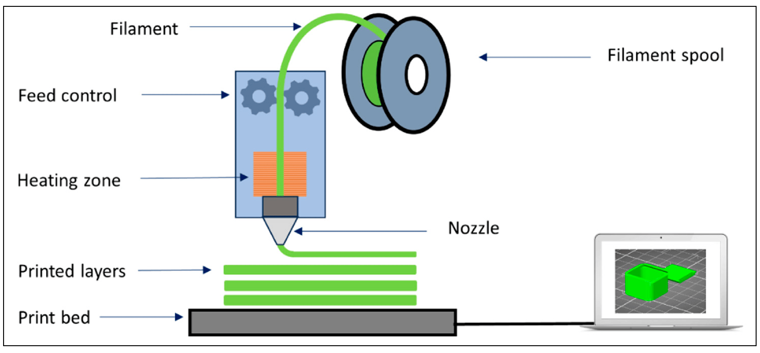
2.1. Design Components and Printing Process
- The semi-solid melt of the material: The amount of material melted by the heating process in the extruder head’s chamber, the temperature of the molten material, the viscosity of the molten material, and the surface tension vary depending on the feed rate [3].
- Extrusion of the melt: Since the geometry of the chamber and nozzle structure significantly affects the behavior and, therefore, the extrusion of the molten material in the chamber, different nozzle designs have been developed [14].
- Motion control: With positional path control, the printing process is completed by printing pre-prepared CAD models in layers [16].
2.2. Materials Used and Their Biomedical Applications
- PLA is a biodegradable material, and due to this property, it is frequently used for low-cost prototypes and biomedical modeling. In addition, it can be sterilized and is biodegradable in the body. As such, they are a potential material for temporary implants or tissue engineering [21]. While it is advantageous to be easy to print, environmentally friendly, and biodegradable, its low heat resistance may limit its applications in the biomedical field [22].
- Polyether Ether Ketone (PEEK) is a thermoplastic known for its high mechanical properties, chemical resistance, and biocompatibility. For this reason, it is widely used for dental implants, orthopedic implants, and medical devices [23]. In addition, it is suitable for sterilization processes because it is resistant to high temperatures [24]. While it has good mechanical properties, such as high-temperature resistance, biocompatibility, strength, and lightness, it can be considered a disadvantage because it requires high printing temperatures (250–350 °C) and special processing equipment.
- Nylon is a durable and flexible material often used in biomedical applications. It is mainly used for prototypes of medical devices, binding elements, and injection parts. It is also used in some types of implants due to its biocompatible properties [25]. While it is a durable, flexible, and chemical-resistant material, it is known as an advantage because it is transparent and cost-effective. At the same time, it has a moisture-absorbing feature and requires processing at high temperatures.
- Thanks to its elastic material properties, Thermoplastic Elastomer (TPE) is used in biomedical devices to produce soft, flexible, and comfortable materials [26]. It is especially suitable for prosthetic parts, orthopedic products, and medical devices. In addition to being soft, flexible, and biocompatible, it is safe for health and ideal for food contact [27]. At the same time, due to its elastic properties, the high precision requirement during the printing phase can be considered a disadvantage.
- Polyvinyl Alcohol (PVA) supports biomedical models with complex geometries [28]. Since PVA is a water-soluble material, it is often combined with other biomedical filaments (e.g., PLA or ABS) [29]. Its high level of biocompatibility and water dissolution is advantageous for supporting complex models, while its easy exposure to moisture requires careful storage.
- Metal Composite Filaments are used for biomedical prototypes and are helpful in the design of implants in some applications [25]. However, these filaments are not used directly in biomedical implants; They are generally preferred for testing and prototyping [23]. Thanks to their durable and strong material structure, they enable the production of genuine metal-looking parts. However, these material properties bring various printing challenges, requiring high-quality and expensive 3D printers.
- Hydroxyapatite (HA) composite filaments are used in implants and biomedical models that promote bone healing due to the properties of hydroxyapatite that are similar to bone tissue [30]. These filaments hold potential, especially for tissue engineering and orthopedic implants [31]. Although it is suitable for tissue engineering applications, mainly due to its compatibility with bone tissue and biocompatibility, printing processes have difficulties [32].
- Bioplastic filaments are produced from biodegradable materials, are environmentally friendly, and are often used in medical applications [33]. The biocompatibility of bioplastics is also essential, and some are suitable for surgical applications. While eco-friendliness is advantageous due to its biodegradability and compatibility with emerging biotechnologies, some bioplastics may have low mechanical properties [34].
2.3. Printing Features and Constraints
3. Features of Electro-Spinning (ES) Platforms
3.1. Design Components and Output Generation Process
- The parameters for the solution used, related to its concentration, determine its viscosity and electrical conductivity, significantly affecting the fibers’ formation. A high concentration can produce thicker fibers, while a low concentration produces finer fibers [46]. The fibers’ critical properties are determined by the solvent’s chemical structure and the solution’s composition (polymer type, solvent, etc.). Polymers can impact fibers’ solubility, viscosity, and durability [47]. High-viscosity solutions can form thicker and more uniform fibers, while low-viscosity solutions produce thinner, more hairy fibers [48]. The pH value of the solution can change the polymer’s structure and the solvent’s effect. The solution’s pH changes can affect the fibers’ morphology [49].
- Electrical parameters are affected by the applied voltage, collector distance, and electrical field intensity. High voltage draws the solution from the liquid in fine fibers in electrospinning. Voltage affects the diameter and morphology of the fiber [50]. Usually, a voltage between 10 and 30 kV is applied [51]. The distance between the solution droplet and the collector constitutes another crucial design parameter [52]. According to the applied voltage, finer and more uniform fibers can be obtained when this distance is more prolonged. The intensity of the electric field allows the solution to be drawn quickly, which in turn affects the size and structure of the fiber [53].
- Temperature and humidity constitute the environmental parameters of this process. Temperature determines the fibers’ properties by influencing the solution’s evaporation rate. The high temperature can help the solvent evaporate quickly, allowing the fibers to form more rapidly [54]. The humidity of the environment can also affect the electrospinning process. High humidity can reduce the rate at which the solvent evaporates and affect the smoothness of the fibers [55].
- The flow rate and the collector’s properties determine the parameters related to system design and its applications. The solution’s flow rate directly affects the fibers’ thickness and shape [56]. A high flow rate produces thicker fibers, while a low flow rate produces thinner fibers [57]. The type of collector surface (flat, 3D structures, etc.) affects the arrangement of the fibers. 3D structures can make the fibers settle more smoothly and in a specific order [58]. The movement of the collector surface can change the orientation and arrangement of the fibers [59].
3.2. Materials Used and Their Biomedical Applications
- Poly (lactic acid) (PLA) is biodegradable and biocompatible. It has high mechanical strength. Tissue engineering, wound dressings, and biomedical devices (e.g., suture threads) are the primary areas of use. PLA is a biodegradable polymer metabolized in the body over time, producing acetic acid. Due to this feature, it is very suitable for medical implants and biomedical applications. It also has favorable surface properties that promote cell growth [67].
- Poly (lactic acid-glycolic acid) (PLGA) is biodegradable, has biocompatible properties, and has a modifiable degradation rate. They are used in tissue engineering, drug delivery, wound healing, and biomedical implants. PLGA is biodegradable and dissolves slowly in the body. These properties make it ideal for long-term drug release and tissue engineering applications. In addition, it is biocompatible and biodegradable, so it does not harm the body [68].
- Polyvinyl alcohol (PVA) is water-soluble, biocompatible, and biodegradable. It is used in wound dressings, biotechnological applications, cell culture, and drug delivery. Due to its high biocompatibility, it is suitable for wound healing and cell interactions. It is also widely used in preparing hydrogels for biomedical applications [69].
- Collagen is a biocompatible and biologically active natural biopolymer. They are used in tissue engineering, wound healing, biological implants, and cell culture studies. Collagen is a protein that occurs naturally in the body, has a very high biological compatibility, and provides a suitable environment for cells to attach and multiply. It is used in tissue engineering, especially in the repair of structures such as skin, bone, and cartilage [70].
- Chitosan (Chitin Derivatives) is natural, biodegradable, biocompatible and antibacterial. Antimicrobial coatings are used in wound healing, tissue engineering, and drug delivery studies. Since Chitosan is a natural polymer with antibacterial properties, it is suitable for wound dressings and biomedical coatings due to its biodegradability and biocompatibility. It promotes cell growth and is used safely in biomedical applications [71].
- Polyurethane (PU) shows high flexibility, biocompatibility, and durability. It is used in tissue engineering, wound dressings, biomedical implants, and biological release systems. Its flexible and biocompatible properties make polyurethane ideal for medical devices and biomedical implants [72].
- Polyacrylonitrile (PAN) has high mechanical strength, is soluble with suitable solvents, and is biocompatible. It is used in drug transport, tissue engineering, carbon fiber production, and biotechnological applications. PAN has properties that are ideal for electrospinning and forming fibers with high mechanical strength. This feature is especially prominent in tissue engineering applications [73].
- Hydrogel polymers (Acrylamide, Polyvinyl Pyrrolidone-PVP, etc.) are biocompatible materials with a high water-holding capacity. It has soft and flexible structural features. It is used in cell culture, wound dressings, biomedical coatings, and drug delivery. Hydrogel polymers are particularly suitable for the growth and interactions of cells in water-based media. It has properties ideal for wound healing and tissue engineering [74].
- Elastin and Elastin Derivatives have flexible, biocompatible, and tissue-compatible properties. It is used in tissue engineering, especially in elastic tissue repair (e.g., blood vessels, lungs). Since it is a natural protein found in the elastic tissues of the body, it has high biocompatibility and flexibility [75].
- Silk Fibroin (Silk Fibers) is a natural polymer that is biocompatible and biodegradable. Structurally, it has high mechanical strength. It is used in tissue engineering, wound dressings, and biotechnological applications [76].
3.3. Output Generation Features and Constraints
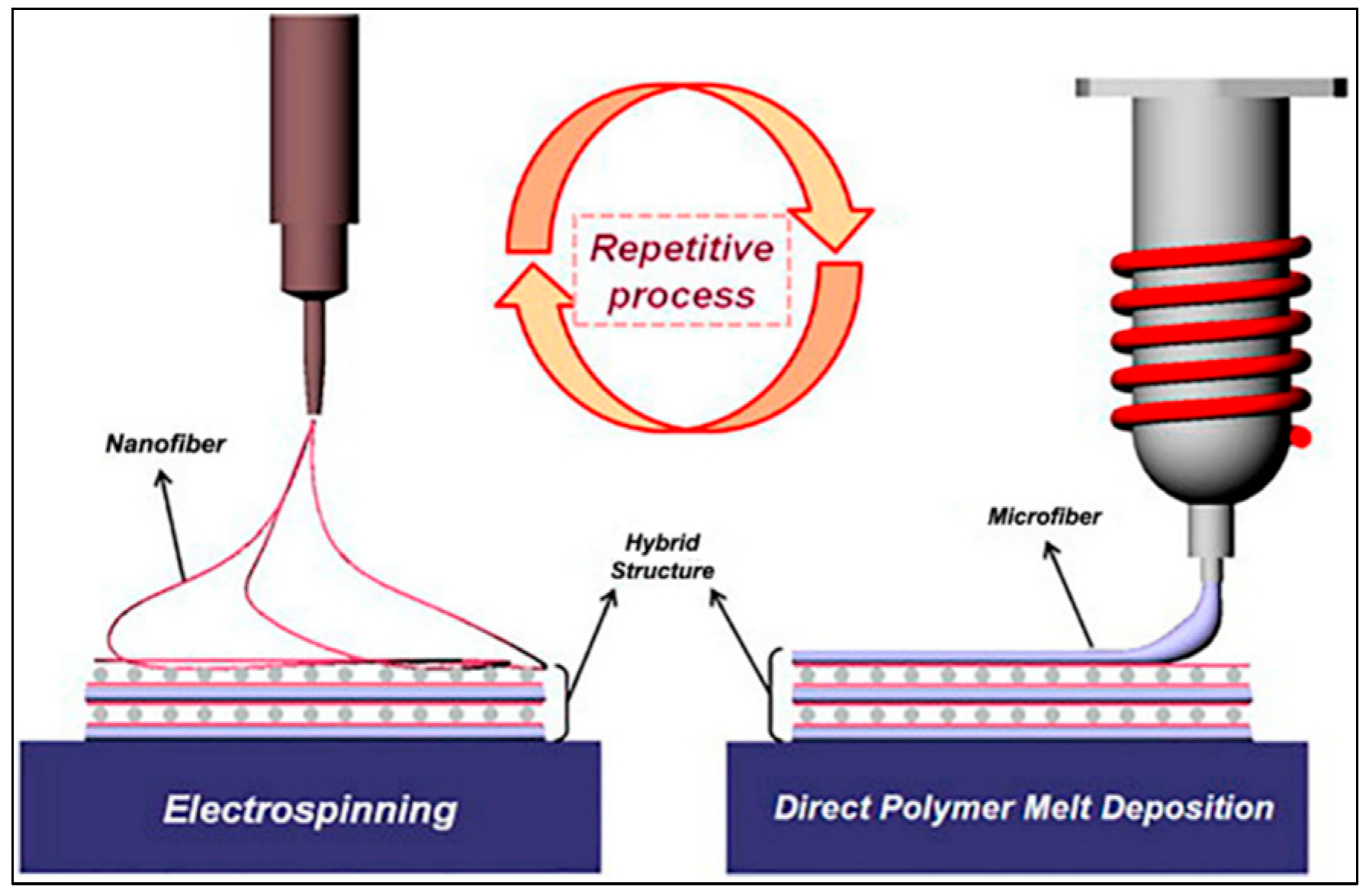
4. MEW as a Hybrid 3D Manufacturing Technique
4.1. Combining Fused Deposition Modelling (FDM) and Electro-Spinning (ES) Techniques
4.2. Working Principle and Processing Steps of Melt Electro Writing (MEW) Technique
- Polymer Selection and Heating: The MEW method usually works with thermoplastic polymers. These polymers are materials that can melt when heated and have a high viscosity. Polymers melt, usually at high temperatures, so they become liquid and have a consistency suitable for printing. Commonly used polymers include PEEK (Polyetheretherketone), PLA (Polylactic Acid), and PCL (Polycaprolactone).
- Feeding of the Melt Polymer: The polymer is melted with the help of a heater and then fed through a thin tip (nozzle). The molten polymer is kept at a specific temperature, ensuring high viscosity and making it suitable for creating fine fibers.
- Attraction by Electrostatic Force: MEW uses electrostatic forces, as in the electrospinning method. The molten polymer is passed through a nozzle to which a high voltage is applied, creating an electrical field. The electric field causes the molten polymer to be pulled like a thin thread. At this stage, the high viscosity of the polymer helps form the fiber more controlled and distinctly.
- Layer-by-Layer Stacked Printing: The thin polymer fibers are drawn and printed on a specific surface by the movement of the print head. This process takes place layer by layer. Printed with high resolution and precision, the fibers are stacked according to the shape of the predetermined 3D model. Printing the polymer at a low speed while molten ensures the layers are placed correctly. The placement of fibers can be regulated in such a way as to create an environment that promotes the growth of cells, especially in tissue engineering and biotechnological applications.
- Cooling and Solidification: The molten polymer fibers cool and solidify rapidly after printing on the surface. This process allows strong bonds to form between the layers and ensures the structural integrity of the printed object. The cooling of the polymer determines the shape and structure of the fiber. The bonds between the layers become stronger during solidification.
- Formation of 3D Structures: At the end of the layer-by-layer printing process, the desired 3D structure is obtained. The fibers’ orientation, solubility, and correct placement determine the object’s mechanical properties and biological compatibility. MEW enables the production of materials that support complex structures and multifaceted cellular interactions, especially with dual-axis and three-dimensional printing processes.
- High Resolution and Sensitivity: The MEW technique can produce particularly fine fibers and provide high resolution. This is very important for applications such as tissue engineering because thin and uniform structures are required for the cells to settle correctly.
- Suitable for Biomedical Applications: MEW can work with biocompatible and biodegradable polymers, making it ideal for tissue engineering and biological implants. Structures that promote the growth and development of cells can be created.
- The High Mechanical Strength of the structures manufactured with MEW is significant for biomedical implants and engineering applications.
- Compliance with the Structures’ Complexity: The high resolution makes creating complex and detailed structures with MEW possible. The arrangement and orientation of the fibers can be customized to design specific structures.
4.3. Design Components of MEW Platforms
4.4. Modification and Redesigning Steps
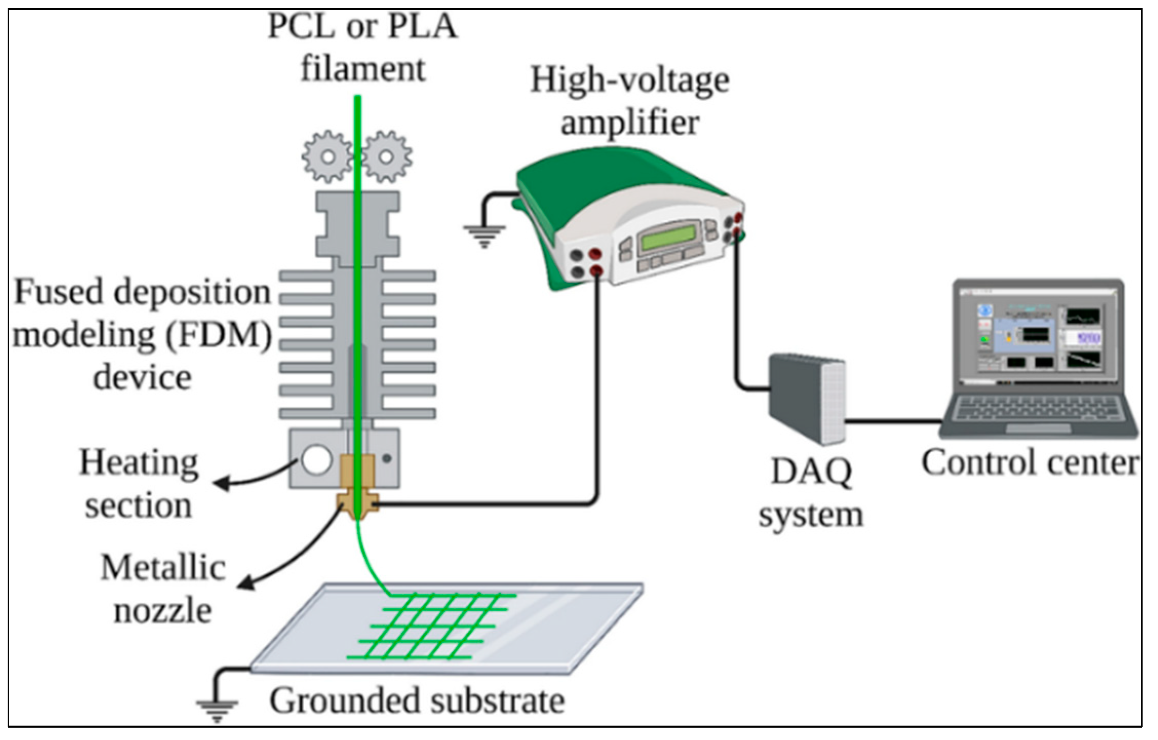
- Printer Hardware: Integrating an MEW system onto a standard FDM printer first requires an electric field applicator mechanism to be added to the extruder system of the FDM printer, making it possible to produce both macro and microstructures with the same printer [12].
- Software Modification: FDM and MEW writing processes must be executed sequentially or in parallel to obtain specific patterns and geometries [90]. Thus, an algorithm is needed to program the sequential FDM and MEW processes.
- Printer Consumables: The basic materials used in the printing phase should be selected from thermoplastic polymers suitable for Fused Deposition Modelling (FDM) and Melt Electro Writing (MEW) technologies. For example, Polycaprolactone (PCL) is a biodegradable and biocompatible polymer widely used for tissue engineering [94]. It is often preferred in FDM and MEW printers. Polylactic acid (PLA) is a biodegradable polymer that is desired to form macrostructures for the FDM process [95].
- High Voltage Electric Field System Integration: MEW uses high voltage to enable the polymer to be printed into fine fibers while in the molten state. Therefore, a power supply that generates high voltage must be integrated into the FDM printer. The power supply should be installed in an area close to the printer’s extruder and properly positioned to allow electrical withdrawal of the polymer.
- High Voltage Usage for MEW applications generally ranges from 5 to 30 kV. For this purpose, a power supply is required to produce low current but high voltage capacity. The voltage range should be adjustable according to the material used and the diameter of the fibers to be generated. The power supply must have a stable and adjustable voltage output. The high-voltage source is used to pull the polymer in a controlled manner and ensure smooth fiber production. The accuracy of the high voltage can directly affect the quality of the fibers to be produced.
- Flow Mechanism of the Melt in MEW: MEW ensures the flow of the melt polymer through the nozzle using electro-hydrodynamic force. By applying a high voltage of 10–30 kV, the polymer melt is drawn towards a target surface grounded in fine fibers [97]. In this process, the surface tension on the melt is broken by the effect of the electric field, and thus, very fine fibers are obtained. The high voltage used in this method allows the polymer to flow in a controlled manner and to form fibers with micrometric diameters [95].
- Metal Grounding Plate: The MEW system uses a metal grounding plate to collect the polymer fibers properly. It is possible to modify the existing print table of the FDM printer with a conductive material. The grounding of this metal table is critical for the controlled printing of the polymer.
- Modification of the Nozzle: The nozzle used in the MEW system has a structure different from that of the FDM nozzle, which allows the polymer to be extruded into fine fibers. Therefore, the FDM printer’s nozzle should be replaced with a smaller diameter for high-temperature control. In addition, the nozzle will need to be insulated and made suitable for high voltage. This must be done to prevent leakage current from occurring when high voltage is applied to the nozzle.
- Adaptation of Printer’s Movement Mechanism and Control System: High precision is required on the FDM printer’s moving x-y-z axes. Since micro-scale production will be made with the MEW method, it may be necessary to increase the movement speed and accuracy of the printer.
- X-Y-Z Axis Motion Precision in FDM generally has an accuracy of 0.1 to 0.2 mm, which is considered sufficient for desktop printers. However, high-precision industrial FDM printers can operate at a resolution of 50 microns (0.05 mm) or less.
- Precision Required for MEW: A much more precise positioning system is required compared to an FDM printer. In MEW, exact x-y-z axis control is used to achieve a resolution of 1–10 microns [98]. This precision is essential for the smooth placement of fibers with high resolution and micrometric size. To achieve this precision, MEW printers use precision motion control systems, such as piezoelectric or linear motors [99]. It is possible to use the existing control system of the FDM printer. Still, based on the printing results obtained, planning a control circuit modification compatible with the MEW process is necessary. This is significant for the nozzle’s movement speed and the high voltage to be controlled in synchronization.
- Temperature control is essential so that the polymer used for MEW can be in a molten state and have the appropriate viscosity. Therefore, it is crucial that the temperature control unit of the extruder is precise and that the polymer can be kept at the correct temperature. The nozzle temperatures required in FDM vary depending on the material used. For example, PLA (Polylactic Acid) is in a typical range of 180–220 °C [100]. PLA is preferred due to its low melting temperature and good fluidity properties. ABS (Acrylonitrile Butadiene Styrene) is used at a temperature of 210–250 °C and has advantages in higher temperature demanding processes [101].
- The polymers used in MEW need to be melted at precise temperatures for viscosity control. Materials such as PCL (Polycaprolactone) melt between 60–90 °C, and the appropriate viscosity is obtained at this temperature [102]. This temperature range enables the production of high-resolution fibers and supports the flow of the polymer under an electric field. The existing temperature control system of the FDM printer must be modified to match the temperature sensitivity to ensure both the fluidity and electrical attraction of the polymers in MEW.
4.5. Comparison of ES and MEW Techniques
4.5.1. Structural and Mechanical Differences
4.5.2. Advanced Scaffolding Design for Tissue Engineering
4.5.3. Differences of Polymers Used in MEW
4.5.4. Cellular Growth and Biocompatibility
4.5.5. Efficiency and Cost-Effective Biomaterial Production
4.5.6. Production Process and Controllability
5. Conclusions
Funding
Data Availability Statement
Conflicts of Interest
References
- Gibson, I.; Rosen, D.; Stucker, B.; Khorasani, M. Development of Additive Manufacturing Technology. In Additive Manufacturing Technologies, 3rd ed.; Springer: Cham, Switzerland, 2021; pp. 23–51. [Google Scholar] [CrossRef]
- Stratasys. Fused Deposition Modeling. Available online: https://www.stratasys.com/en/about-us/ (accessed on 6 December 2024).
- Stevens, M.J.; Covas, J.A. Extruder Principles and Operation, 2nd ed.; Springer: Dordrecht, The Netherlands, 1995; pp. 352–383. [Google Scholar] [CrossRef]
- Yardimci, M.A.; Guceri, S. Conceptual framework for the thermal process of fused deposition. Rapid Prototyp. J. 1996, 2, 26–31. [Google Scholar] [CrossRef]
- Smid, P. Programming Approach. In CNC Programming Techniques: An Insider’s Guide to Effective Methods and Applications, 1st ed.; Smid, P., Ed.; Industrial Press Inc.: New York, NY, USA, 2006; pp. 147–156. ISBN 0831131853/9780831131852. [Google Scholar]
- Agarwala, M.; Jamalabad, V.; Langrana, N.; Safari, A.; Whalen, P.; Danforth, S. Structural quality of parts processed by fused deposition. Rapid Prototyp. J. 1996, 2, 4–19. [Google Scholar] [CrossRef]
- Manea, L.R.; Scarlet, R.; Leon, A.; Sandu, I. Control of Nanofibers production process through electrospinning. Rev. Chim. 2015, 66, 640–644. [Google Scholar]
- Leung, V.; Ko, F. Biomedical applications of nanofibers. Polym. Adv. Technol. 2011, 22, 350–365. [Google Scholar] [CrossRef]
- Greiner, A.; Wendorff, J.H. Electrospinning: A fascinating method for the preparation of ultrathin fibers. Angew. Chem. Int. Ed. Engl. 2007, 46, 5670–5703. [Google Scholar] [CrossRef]
- Greiner, A.; Wendorff, J.H. Functional self-assembled nanofibers by electrospinning. Adv. Polym. Sci. 2008, 219, 107–171. [Google Scholar] [CrossRef]
- Wendorff, J.H.; Agarwal, S.; Greiner, A. Electrospinning: Materials, Processing, and Applications, 1st ed.; Wiley-VCH Verlag GmbH Co., KGaA: Weinheim, Germany, 2012; pp. 29–183. [Google Scholar] [CrossRef]
- Dalton, P.D. Melt electrowriting with additive manufacturing principles. Curr. Opin. Biomed. Eng. 2017, 2, 49–57. [Google Scholar] [CrossRef]
- Haque, A.N.M.A.; Naebe, M. Tensile Properties of Natural Fibre-Reinforced FDM Filaments: A Short Review. Sustainability 2023, 15, 16580. [Google Scholar] [CrossRef]
- Ramanath, H.S.; Chua, C.K.; Leong, K.F.; Shah, K.D. Melt flow behavior of poly-epsilon-caprolactone in fused deposition modeling. J. Mater. Sci. Mater. Med. 2007, 19, 2541–2550. [Google Scholar] [CrossRef]
- Bellini, A.; Güçeri, S. Mechanical characterization of parts fabricated using fused deposition modeling. Rapid Prototyp. J. 2003, 9, 252–264. [Google Scholar] [CrossRef]
- Sachs, E.; Cima, M.; Cornie, J. Three Dimensional Printing: Rapid Tooling and Prototypes Directly from CAD Representation. CIRP Ann. 1990, 39, 201–204. [Google Scholar] [CrossRef]
- Boparai, K.; Singh, R.; Singh, H. Development of rapid tooling using fused deposition modeling: A review. Rapid Prototyp. J. 2016, 22, 281–299. [Google Scholar] [CrossRef]
- Rodriguez, J.F.; Thomas, J.P.; Renaud, J.E. Design of Fused-Deposition ABS Components for Stiffness and Strength. J. Mech. Des. 2003, 125, 545–551. [Google Scholar] [CrossRef]
- Smith, W.C.; Dean, R.W. Structural characteristics of fused deposition modeling polycarbonate material. Polym. Test. 2013, 32, 1306–1312. [Google Scholar] [CrossRef]
- Pascual-González, C.; Thompson, C.; de la Vega, J.; Churruca, N.B.; Fernandez-Blazquez, J.; Lizarralde, I.; Herraez-Molinero, D.; Llorca, C. Processing and properties of PLA/Mg filaments for 3D printing of scaffolds for biomedical applications. Rapid Prototyp. J. 2022, 28, 884–894. [Google Scholar] [CrossRef]
- Alam, F.; Shukla, V.R.; Varadarajan, K.M.; Kumar, S. Microarchitected 3D printed polylactic acid (PLA) nanocomposite scaffolds for biomedical applications. J. Mech. Behav. Biomed. Mater. 2020, 103, 103576. [Google Scholar] [CrossRef]
- Buj-Corral, I.; Sanz-Fraile, H.; Ulldemolins, A.; Tejo-Otero, A.; Dominguez-Fernandez, A.; Almendros, I.; Otero, J. Characterization of 3D printed metal-PLA composite scaffolds for biomedical applications. Polymers 2022, 14, 2754. [Google Scholar] [CrossRef]
- Vaezi, M.; Yang, S. Extrusion-based additive manufacturing of PEEK for biomedical applications. Virtual Phys. Prototyp. 2015, 10, 123–135. [Google Scholar] [CrossRef]
- Vindokurov, I.; Pirogova, Y.; Tashkinov, M.; Silberschmidt, V.V. Effect of heat treatment on elastic properties and fracture toughness of fused filament fabricated PEEK for biomedical applications. Polymers 2022, 14, 5521. [Google Scholar] [CrossRef]
- Shakiba, M.; Ghomi, E.R.; Khosravi, F.; Jouybar, S.; Bigham, A.; Zare, M.; Abdouss, M.; Moaref, R.; Ramakrishna, S. Nylon—A material introduction and overview for biomedical applications. Polym. Adv. Technol. 2021, 32, 3368–3383. [Google Scholar] [CrossRef]
- Adrover, B.; Lljuma, J.; Jerez, R.; Travieso, J.A. Tensile properties of elastomer process through FFF for biomedical applications. In Proceedings of the IOP Conference Series: Materials Science and Engineering, Volume 1193, 9th Manufacturing Engineering Society International Conference (MESIC 2021), Gijόn, Spain, 23–25 June 2021. [Google Scholar] [CrossRef]
- Shaalan, M.; Vykydalova, A.; Svajdlenkova, H.; Kronekova, Z.; Markovic, Z.M.; Kovakova, M.; Spitalsky, Z. Antibacterial activity of 3D printed thermoplastic elastomers doped with carbon quantum dots for biomedical applications. Polym. Bull. 2024, 81, 13009–13025. [Google Scholar] [CrossRef]
- Kumar, A.V.; Vishal, F.; Chandrashekhar, A. Multi objective optimization of 3D printed PVA for biomedical application. AIP Conf. Proc. 2024, 2962, 20017. [Google Scholar] [CrossRef]
- Malloum, A.H.; Aiman, A.F.; Zain, M.Z.M.; Jaafar, M.H.M.; Azman, M.D. The effect of PLA/PVA composition in FDM filament towards porosity behavior for medical applications. AIP Conf. Proc. 2023, 2544, 40024. [Google Scholar] [CrossRef]
- Kim, C.G.; Han, K.S.; Lee, S.; Kim, M.C.; Kim, S.Y.; Nah, J. Fabrication of biocompatible polycaprolactone–hydroxyapatite composite filaments for the FDM 3D printing of bone scaffolds. Appl. Sci. 2021, 11, 6351. [Google Scholar] [CrossRef]
- Yanting, H.; Wei, Q.; Chang, P.; Hu, K.; Okoro, O.V.; Shavandi, A.; Nie, L. Three-dimensional printing of hydroxyapatite composites for biomedical application. Crystals 2021, 11, 353. [Google Scholar] [CrossRef]
- Orozco-Díaz, C.A.; Moorehead, R.; Reilly, G.C.; Gilchrist, F.; Miller, C. Characterization of a composite polylactic acid-hydroxyapatite 3D-printing filament for bone-regeneration. Biomed. Phys. Eng. Express 2020, 6, 25007. [Google Scholar] [CrossRef]
- Calì, M.; Pascoletti, G.; Gaeta, M.; Milazzo, G.; Ambu, R. A new generation of bio-composite thermoplastic filaments for a more sustainable design of parts manufactured by FDM. Appl. Sci. 2020, 10, 5852. [Google Scholar] [CrossRef]
- Andanje, M.N.; Mwangi, J.W.; Mose, B.R.; Carrara, S. Biocompatible and biodegradable 3D printing from bioplastics: A review. Polymers 2023, 15, 2355. [Google Scholar] [CrossRef]
- Athira, K.S.; Sanpui, P.; Chatterjee, K. Fabrication of poly(caprolactone) nanofibers by electrospinning. J. Polym. Biopolym. Phys. Chem. 2014, 2, 62–66. [Google Scholar]
- Langwald, S.V.; Ehrmann, A.; Sabantina, L. Measuring physical properties of electrospun nanofiber mats for different biomedical applications. Membranes 2023, 13, 488. [Google Scholar] [CrossRef]
- He, J.H.; Liu, Y.; Mo, L.F.; Wan, Y.Q.; Xu, L. Electrospun Nanofibres and Their Applications; ISmithers: Shawbury, UK, 2008; pp. 1–16. [Google Scholar]
- Aditya, K.; Bambole, V.A.; Mahanwar, P.A. Electrospinning of polymers, their modeling and applications. Polym. Plast. Technol. Eng. 2010, 49, 427–441. [Google Scholar] [CrossRef]
- Karatay, O.; Dogan, M. Modelling of electrospinning process at various electric fields. Micro Nano Lett. 2011, 6, 858–862. [Google Scholar] [CrossRef]
- Yarin, A.L.; Koombhongse, S.; Reneker, D.H. Taylor cone and jetting from liquid droplets in electrospinning of nanofibers. J. Appl. Phys. 2001, 90, 4836–4846. [Google Scholar] [CrossRef]
- Reneker, D.H.; Yarin, A.L. Electrospinning jets and polymer nanofibers. Polymer 2008, 49, 2387–2425. [Google Scholar] [CrossRef]
- Stanger, J.; Tucker, N.; Kirwan, K.; Staiger, M.P. Effect of charge density on the Taylor cone in electrospinning. Int. J. Mod. Phys. B. 2009, 23, 1956–1961. [Google Scholar] [CrossRef]
- Chinnappan, B.A.; Krishnaswamy, M.; Xu, H.; Hoque, M.E. Electrospinning of biomedical nanofibers/nanomembranes: Effects of process parameters. Polymers 2022, 14, 3719. [Google Scholar] [CrossRef]
- Fang, J.; Niu, H.T.; Wang, X.G. Applications of electrospun nanofibers. Chin. Sci. Bull. 2008, 53, 2265–2286. [Google Scholar] [CrossRef]
- Fang, J.; Wang, X.; Lin, T. Functional Applications of Electrospun Nanofibers. In Nanofibers-Production, Properties and Functional Applications; Lin, T., Ed.; InTech: Rijeka, Croatia, 2011; pp. 287–309. [Google Scholar] [CrossRef]
- Angammana, C.J.; Jayaram, S.H. Analysis of the Effects of Solution Conductivity on Electrospinning Process and Fiber Morphology. IEEE Trans. Ind. Appl. 2011, 47, 1109–1117. [Google Scholar] [CrossRef]
- Chen, H.; Yossef, A.E. Polymerized ionic liquids: Solution properties and electrospinning. Macromolecules 2009, 42, 3368–3373. [Google Scholar] [CrossRef]
- Tiwari, S.K.; Venkatraman, S.S. Importance of viscosity parameters in electrospinning: Of monolithic and core-shell fibers. Mater. Sci. Eng. C 2012, 32, 1037–1042. [Google Scholar] [CrossRef]
- Son, W.K.; Youk, J.H.; Lee, T.S.; Park, W.H. Effect of pH on electrospinning of poly (vinyl alcohol). Mater. Lett. 2005, 59, 1571–1575. [Google Scholar] [CrossRef]
- Şener, A.G.; Altay, A.S.; Altay, F. Effect of voltage on morphology of electrospun nanofibers. In Proceedings of the ELECO 2011—7th International Conference on Electrical and Electronics Engineering, Bursa, Turkey, 1–4 December 2011; pp. 1324–1328, ISBN 978-605010204-8. [Google Scholar]
- Doshi, J.; Reneker, D.H. Electrospinning process and applications of electrospun fibers. J. Electrost. 1995, 35, 151–160. [Google Scholar] [CrossRef]
- Jabur, A.R.; Abbas, L.K.; Muhi, S.M. Effects of ambient temperature and needle to collector distance on PVA nanofibers diameter obtained from electrospinning technique. Eng. Technol. J. 2017, 35, 340–347. [Google Scholar] [CrossRef]
- Angammana, C.J.; Jayaram, S.H. The effects of electric field on the multijet electrospinning process and fiber morphology. IEEE Trans. Ind. Appl. 2011, 47, 1028–1035. [Google Scholar] [CrossRef]
- Huang, F.; Wei, Q.u.f.u.; Wang, J.; Cai, Y.; Huang, Y. Effect of temperature on structure, morphology and crystallinity of PVDF nanofibers via electrospinning. e-Polymers 2008, 8, 152. [Google Scholar] [CrossRef]
- Nezarati, R.M.; Eifert, M.B.; Cosgriff-Hernandez, E. Effects of humidity and solution viscosity on electrospun fiber morphology. Tissue Eng. Part C Methods 2013, 19, 810–819. [Google Scholar] [CrossRef]
- He, J.H.; Wan, Y.Q.; Yu, J.Y. Scaling law in electrospinning: Relationship between electric current and solution flow rate. Polymer 2005, 46, 2799–2801. [Google Scholar] [CrossRef]
- Cramariuc, B.; Cramariuc, R.; Scarlet, R.; Manea, L.R.; Lupu, I.G.; Cramariuc, O. Fiber diameter in electrospinning process. J. Electrost. 2013, 71, 189–198. [Google Scholar] [CrossRef]
- Zhou, Y.; Hu, Z.; Du, D.; Tan, G.Z. The effects of collector geometry on the internal structure of the 3D nanofiber scaffold fabricated by divergent electrospinning. Int. J. Adv. Manuf. Technol. 2019, 100, 3045–3054. [Google Scholar] [CrossRef]
- Demirtas, M.; Saha, M. Investigation of Collector Geometry and Speed on Orientation, Diameter Distribution and Mechanical Properties of Electrospun Nanofibers. In Proceedings of the American Society for Composites: Thirty-First Technical Conference, Williamsburg, VA, USA, 19–22 September 2016; ISBN 978-1-60595-316-8. [Google Scholar]
- Al-Abduljabbar, A.; Farooq, I. Electrospun polymer nanofibers: Processing, properties, and applications. Polymers 2022, 15, 65. [Google Scholar] [CrossRef]
- Supaphol, P.; Suwantong, O.; Sangsanoh, P.; Srinivasan, S.; Jayakumar, R.; Nair, S.V. Electrospinning of Biocompatible Polymers and Their Potentials in Biomedical Applications. In Biomedical Applications of Polymeric Nanofibers. Advances in Polymer Science, 1st ed.; Nair, J., Ed.; Springer: Berlin/Heidelberg, Germany, 2011; pp. 213–240. [Google Scholar] [CrossRef]
- Nayl, A.; Abd-Elhamid, A.I.; Awwad, N.S.; Abdelgawad, M.A.; Wu, J.; Mo, X.; Gomha, S.M.; Aly, A.A.; Brase, S. Recent progress and potential biomedical applications of electrospun nanofibers in regeneration of tissues and organs. Polymers 2022, 14, 1508. [Google Scholar] [CrossRef] [PubMed]
- Bhattarai, R.S.; Bachu, R.D.; Boddu, S.H.S.; Bhaduri, S. Biomedical applications of electrospun nanofibers: Drug and nanoparticle delivery. Pharmaceutics 2019, 11, 5. [Google Scholar] [CrossRef] [PubMed]
- Liu, X.; Xu, H.; Zhang, M.; Yu, D.G. Electrospun medicated nanofibers for wound healing. Membranes 2021, 11, 770. [Google Scholar] [CrossRef] [PubMed]
- Maliszewska, I.; Czapka, T. Electrospun polymer nanofibers with antimicrobial activity. Polymers 2022, 14, 1661. [Google Scholar] [CrossRef]
- Rasouli, R.; Barhoum, A.; Bechelany, M.; Dufresne, A. Nanofibers for biomedical and healthcare applications. Macromol. Biosci. 2019, 19, e1800256. [Google Scholar] [CrossRef]
- Li, Y.; Lim, C.T.; Kotaki, M. Study on structural and mechanical properties of porous PLA nanofibers electrospun by channel-based electrospinning system. Polymer 2015, 56, 572–580. [Google Scholar] [CrossRef]
- Lohitha, K.; Satpathy, M.; Duan, Y. Effect of electrospinning parameters on the fiber diameter and morphology of PLGA nanofibers. Dent. Oral Biol. Craniofacial Res. 2021, 4, 1–7. [Google Scholar] [CrossRef]
- Alwan, T.J.; Toma, Z.A.; Kudhier, M.A.; Ziadan, K.M. Preparation and characterization of the PVA nanofibers produced by electrospinning. Madridge J. Nanotechnol. Nanosci. 2016, 1, 1–3. [Google Scholar] [CrossRef]
- Matthews, J.A.; Wnek, G.E.; Sİmpson, D.G.; Bowlin, G.L. Electrospinning of collagen nanofibers. Biomacromolecules 2002, 3, 232–238. [Google Scholar] [CrossRef]
- Homayoni, H.; Ravandi, S.A.H.; Valizadeh, M. Electrospinning of chitosan nanofibers: Processing optimization. Carbohydr. Polym. 2009, 77, 656–661. [Google Scholar] [CrossRef]
- Zhuo, H.; Hu, J.; Chen, S.; Yeung, L. Preparation of polyurethane nanofibers by electrospinning. J. Appl. Polym. Sci. 2008, 109, 406–411. [Google Scholar] [CrossRef]
- Wang, T.; Kumar, S. Electrospinning of polyacrylonitrile nanofibers. J. Appl. Polym. Sci. 2006, 102, 1023–1029. [Google Scholar] [CrossRef]
- Xu, S.; Deng, L.; Zhang, J.; Yin, L.; Dong, A. Composites of electrospun-fibers and hydrogels: A potential solution to current challenges in the biological and biomedical field. J. Biomed. Mater. Res. Part B Appl. Biomater. 2015, 104, 640–656. [Google Scholar] [CrossRef] [PubMed]
- Buttafoco, L.; Kolkman, N.G.; Engbers-Buijtenhuijs, P.; Poot, A.A.; Dijkstra, P.J.; Vermes, I.; Feijen, J. Electrospinning of collagen and elastin for tissue engineering applications. Biomaterials 2006, 27, 724–734. [Google Scholar] [CrossRef]
- Kim, S.H.; Nam, Y.S.; Lee, T.S.; Park, W.H. Silk Fibroin Nanofiber. Electrospinning, Properties, and Structure. Polym. J. 2003, 35, 185–190. [Google Scholar] [CrossRef]
- Mironov, V.; Visconti, R.P.; Kasyanov, V.; Forgacs, G.; Drake, C.J.; Markwald, R.R. Organ printing: Tissue spheroids as building blocks. Biomaterials 2009, 30, 2164–2174. [Google Scholar] [CrossRef]
- Ozbolat, I.T.; Hospodiuk, M. Current advances and future perspectives in extrusion-based bioprinting. Biomaterials 2016, 76, 321–343. [Google Scholar] [CrossRef]
- Murphy, S.; Atala, A. 3D bioprinting of tissues and organs. Nat. Biotechnol. 2014, 32, 773–785. [Google Scholar] [CrossRef]
- Shahverdi, M.; Seifi, S.; Akbari, A.; Mohammadi, K.; Shamloo, A.; Movahhedy, M.R. Melt electrowriting of PLA, PCL, and composite PLA/PCL scaffolds for tissue engineering application. Sci. Rep. 2022, 12, 19935. [Google Scholar] [CrossRef]
- Montez, M.; Willis, K.; Rendler, H.; Marshall, C.; Rubio, E.; Rajak, D.K.; Rahman, M.H.; Menezes, P.L. Fused deposition modeling (FDM): Processes, material properties, and applications. In Tribology of Additively Manufactured Materials; Elsevier Series on Tribology and Surface Engineering; Kumar, P., Misra, M., Menezes, P.L., Eds.; Elsevier: Amsterdam, The Netherlands, 2022; pp. 137–163. [Google Scholar] [CrossRef]
- Tsioukas, V.; Pikridas, C.; Karolos, I.A. Challenges, opportunities, and limitations in 3D printing. 3D Print. Appl. Med. Surg. 2020, 1, 151–155. [Google Scholar] [CrossRef]
- Bhardwaj, N.; Kundu, S.C. Electrospinning: A fascinating fiber fabrication technique. Biotechnol. Adv. 2010, 28, 325–347. [Google Scholar] [CrossRef] [PubMed]
- Baji, A.; Mai, Y.W.; Wong, S.C.; Abtahi, M.; Chen, P. Electrospinning of polymer nanofibers: Effects on oriented morphology, structures and tensile properties. Compos. Sci. Technol. 2010, 70, 703–718. [Google Scholar] [CrossRef]
- Jian, S.; Zhu, J.; Jiang, S.; Chen, S.; Fang, H.; Song, Y.; Duan, G.; Zhang, Y.; Hou, H. Nanofibers with diameter below one nanometer from electrospinning. RSC Adv. 2018, 8, 4794–4802. [Google Scholar] [CrossRef] [PubMed]
- Wunner, F.M.; Eggert, S.; Maartens, J.; Bas, O.; Dalton, P.D.; De-Juan-Pardo, E.M.; Hutmacher, D.W. Design and development of a three-dimensional printing high-throughput melt electrowriting technology platform. 3d Print. Addit. Manuf. 2019, 6, 82–90. [Google Scholar] [CrossRef]
- Hutmacher, D.W. Scaffolds in tissue engineering bone and cartilage. Biomaterials 2000, 21, 2529–2543. [Google Scholar] [CrossRef]
- Paxton, N.C.; Dalton, P.D. Biofabricated Tissues and Organs. In 3D Printing at Hospitals and Medical Centers; Rybicki, F.J., Morris, J.M., Grant, G.T., Eds.; Springer International Publishing: Cham, Switzerland, 2024; pp. 341–359. [Google Scholar] [CrossRef]
- Muerza-Cascante, M.L.; Haylock, D.; Hutmacher, D.W.; Dalton, P.D. Melt electrospinning and its technologization in tissue engineering. Tissue Eng. Part B Rev. 2014, 21, 187–202. [Google Scholar] [CrossRef]
- Brown, T.D.; Dalton, P.D.; Hutmacher, D.W. Melt electrospinning today: An opportune time for an emerging polymer process. Prog. Polym. Sci. 2016, 56, 116–166. [Google Scholar] [CrossRef]
- Gora, A.; Shay, R.; Thavasi, V.; Ramakrishna, S. Melt-electrospun fibers for advances in biomedical engineering, clean energy, filtration, and separation. Polym. Rev. 2011, 51, 265–287. [Google Scholar] [CrossRef]
- Hochleitner, G.; Jüngst, T.; Brown, T.D.; Hahn, K.; Moseke, C.; Jakob, F.; Dalton, P.D.; Groll, J. Additive manufacturing of scaffolds with sub-micron filaments via melt electrospinning writing. Biofabrication 2015, 7, 35002. [Google Scholar] [CrossRef]
- New 3D Printing Technique Unleashes New Surgical Mesh Designs and Properties. Available online: https://www.3d4makers.com/blogs/news/new-3d-printing-technique-unleashes-new-surgical-mesh-designs-and-properties (accessed on 24 December 2024).
- Mouser, V.; Levato, R.; Bonassar, L.J.; D’Lima, D.D.; Grande, D.A.; Klein, T.J.; Saris, D.B.F.; Zenobi-Wong, M.; Gawlitta, D.; Malda, J. Three-dimensional bioprinting and its potential in the field of articular cartilage regeneration. Cartilage 2017, 8, 327–340. [Google Scholar] [CrossRef]
- Cuiffo, M.A.; Snyder, J.; Elliot, A.M.; Romero, N.; Kannan, S.; Halada, G.P. Impact of the fused deposition (FDM) printing process on polylactic acid (PLA) chemistry and structure. Appl. Sci. 2017, 7, 579. [Google Scholar] [CrossRef]
- Golobic, A.M.; Durban, M.D.; Fİsher, S.E.; Grapes, M.D.; Ortega, J.M.; Spadaccini, C.M.; Duoss, E.B.; Gash, A.E.; Sullivan, K.T. Active mixing of reactive materials for 3D printing. Adv. Eng. Mater. 2019, 21, 1900147. [Google Scholar] [CrossRef]
- Lu, H.; Sun, Y.; Chen, Y.; Nie, L.; Yang, L.; Du, L.; Xu, H. The effects of voltage configurations on print accuracy in melt electrowriting. Mater. Lett. 2023, 334, 133738. [Google Scholar] [CrossRef]
- Eichholz, K.F.; Gonçalves, I.; Barcelo, X.; Federici, A.S.; Hoey, D.A.; Kelly, D.J. How to design, develop and build a fully-integrated melt electrowriting 3D printer. Addit. Manuf. 2022, 58, 102998. [Google Scholar] [CrossRef]
- Mieszczanek, P.; Eggert, S.; Corke, P.; Hutmacher, D.W. Automated melt electrowritting platform with real-time process monitoring. HardwareX 2021, 10, e00246. [Google Scholar] [CrossRef]
- Backes, E.H.; Harb, S.V.; Beatrice, C.A.G.; Shimomura, K.M.B.; Passador, F.R.; Costa, L.C.; Pessan, L.A. Polycaprolactone usage in additive manufacturing strategies for tissue engineering applications: A review. J. Biomed. Mater. Res. B Appl. Biomater. 2022, 110, 1479–1503. [Google Scholar] [CrossRef]
- Zhang, H.; Cai, L.; Golub, M.; Zhang, Y.; Yang, X.; Schlarman, K.; Zhang, J. Tensile, creep, and fatigue behaviors of 3D-printed acrylonitrile butadiene styrene. J. Mater. Eng. Perform. 2018, 27, 57–62. [Google Scholar] [CrossRef]
- Kade, J.C.; Dalton, P.D. Polymers for melt electrowriting. Adv Healthc. Mater. 2021, 10, e2001232. [Google Scholar] [CrossRef]
- Henkel, J.; Hutmacher, D.W. Design and fabrication of scaffold-based tissue engineering. BioNanoMaterials 2013, 14, 171–193. [Google Scholar] [CrossRef]
- Lian, H.; Meng, Z. Melt electrospinning vs. solution electrospinning: A comparative study of drug-loaded poly (ε-caprolactone) fibres. Mater. Sci. Eng. C 2017, 74, 117–123. [Google Scholar] [CrossRef]
- Hrynevich, A.; Elçi, B.Ş.; Haigh, J.N.; McMaster, R.; Youssef, A.; Blum, C.; Blunk, T.; Hochleitner, G.; Groll, J.; Dalton, P.D. Dimension-based design of melt electrowritten scaffolds. Small 2018, 14, 1800232. [Google Scholar] [CrossRef] [PubMed]
- Cao, K.; Zhang, F.; Zaeri, A.; Zhang, Y.; Zgeib, R.; Calzolaio, M.; Chang, R.C. Advances in design and quality of melt electrowritten scaffolds. Mater. Des. 2023, 226, 111618. [Google Scholar] [CrossRef]
- Inai, R.; Kotaki, M.; Ramakrishna, S. Structure and properties of electrospun PLLA single nanofibres. Nanotechnology 2005, 16, 208. [Google Scholar] [CrossRef] [PubMed]
- Saiz, P.G.; Reizebal, A.; Vilas-Vilela, J.L.; Dalton, P.D.; Lanceros-Mendez, S. Materials and Strategies to Enhance Melt Electrowriting Potential. Adv. Mater. 2024, 36, e2312084. [Google Scholar] [CrossRef]
- Loewner, S.; Heene, S.; Baroth, T.; Heymann, H.; Cholewa, F.; Blume, H.; Blume, C. Recent advances in melt electro writing for tissue engineering for 3D printing of microporous scaffolds for tissue engineering. Front. Bioeng. Biotechnol. 2022, 10, 896719. [Google Scholar] [CrossRef]
- Langer, R.; Vacanti, J.P. Tissue engineering. Science 1993, 260, 920–926. [Google Scholar] [CrossRef]
- Jin, Y.; Gao, Q.; Xie, C.; Li, G.; Du, J.; Fu, J.; He, Y. Fabrication of heterogeneous scaffolds using melt electrospinning writing: Design and optimization. Mater. Des. 2020, 185, 108274. [Google Scholar] [CrossRef]
- Daneshfar, A.; Edwards, S.L.; Dumee, L.F.; Kong, L.; Hughes, T.C. Predicting operating rules for successful melt electrowriting. ACS Appl. Polym. Mater. 2021, 3, 1890–1898. [Google Scholar] [CrossRef]
- Warren, P.B.; Davis, Z.G.; Fisher, M.B. Parametric control of fiber morphology and tensile mechanics in scaffolds with high aspect ratio geometry produced via melt electrowriting for musculoskeletal soft tissue engineering. J. Mech. Behav. Biomed. Mater. 2019, 99, 153–160. [Google Scholar] [CrossRef]
- Hutmacher, D.W.; Goh, J.C.; Teoh, S.H. An introduction to biodegradable materials for tissue engineering applications. Ann. Acad. Med. Singap. 2001, 30, 183–191. [Google Scholar]
- Do, A.V.; Khorsand, B.; Geary, S.M.; Salem, A.K. 3D Printing of Scaffolds for Tissue Regeneration Applications. Adv. Healthc. Mater. 2015, 4, 1742–1762. [Google Scholar] [CrossRef] [PubMed]
- Jiajia, X.; Wu, T.; Dai, Y.; Xia, Y. Electrospinning and electrospun nanofibers: Methods, Materials, and Applications. Chem. Rev. 2019, 119, 5298–5415. [Google Scholar] [CrossRef]
- O’Neill, K.L.; Dalton, P.D. A decade of melt electrowriting. Small Methods 2023, 7, 2201589. [Google Scholar] [CrossRef] [PubMed]
- Reizabal, A.; Kangur, T.; Saiz, P.G.; Menke, S.; Moser, C.; Brugger, J.; Dalton, P.D.; Luposchainsky, S. MEWron: An open-source melt electrowriting platform. Addit. Manuf. 2023, 71, 103604. [Google Scholar] [CrossRef]
- Turner, B.N.; Strong, R.; Gold, S.A. A review of melt extrusion additive manufacturing processes: I. Process design and modeling. Rapid Prototyp. J. 2014, 20, 192–204. [Google Scholar] [CrossRef]


Disclaimer/Publisher’s Note: The statements, opinions and data contained in all publications are solely those of the individual author(s) and contributor(s) and not of MDPI and/or the editor(s). MDPI and/or the editor(s) disclaim responsibility for any injury to people or property resulting from any ideas, methods, instructions or products referred to in the content. |
© 2025 by the author. Licensee MDPI, Basel, Switzerland. This article is an open access article distributed under the terms and conditions of the Creative Commons Attribution (CC BY) license (https://creativecommons.org/licenses/by/4.0/).
Share and Cite
Turker, B. Redesigning FDM Platforms for Bio-Printing Applications. Micromachines 2025, 16, 226. https://doi.org/10.3390/mi16020226
Turker B. Redesigning FDM Platforms for Bio-Printing Applications. Micromachines. 2025; 16(2):226. https://doi.org/10.3390/mi16020226
Chicago/Turabian StyleTurker, Burak. 2025. "Redesigning FDM Platforms for Bio-Printing Applications" Micromachines 16, no. 2: 226. https://doi.org/10.3390/mi16020226
APA StyleTurker, B. (2025). Redesigning FDM Platforms for Bio-Printing Applications. Micromachines, 16(2), 226. https://doi.org/10.3390/mi16020226