


The Woofer-Type Piezo-Actuated Microspeaker Based on Aerosol Deposition and Metal MEMS Process


Abstract
1. Introduction
2. Theoretical Analysis and Simulation
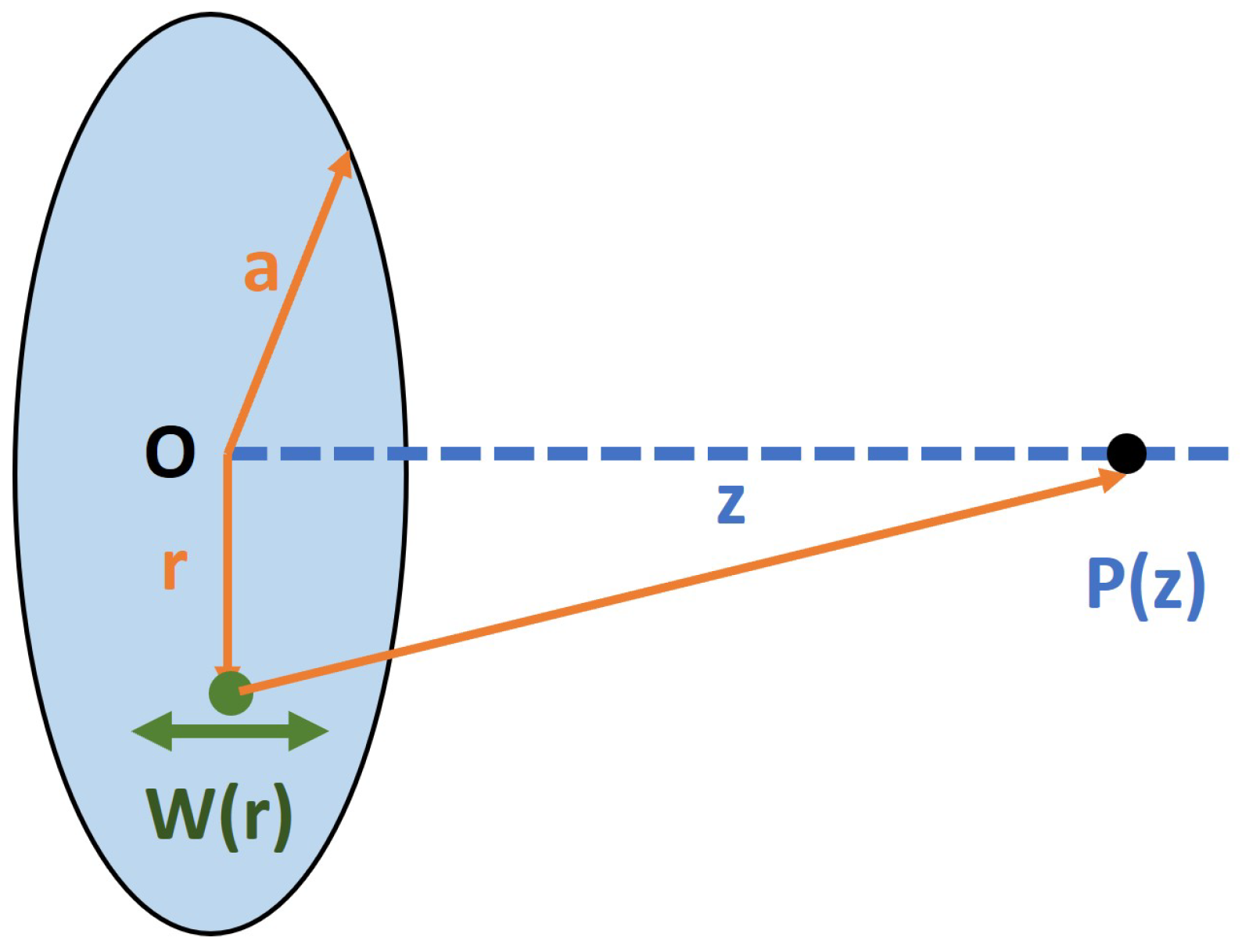
2.1. Free-Field Acoustic Analysis
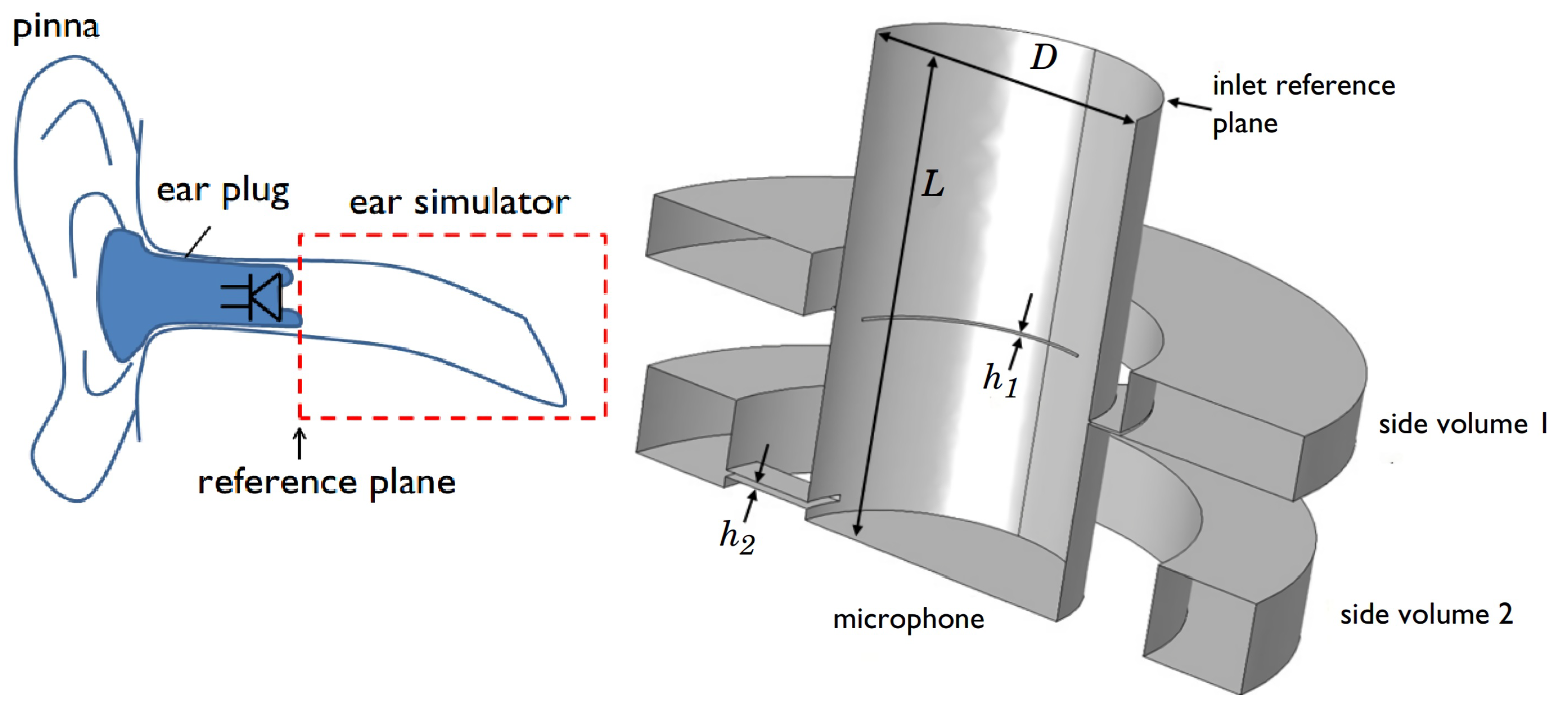
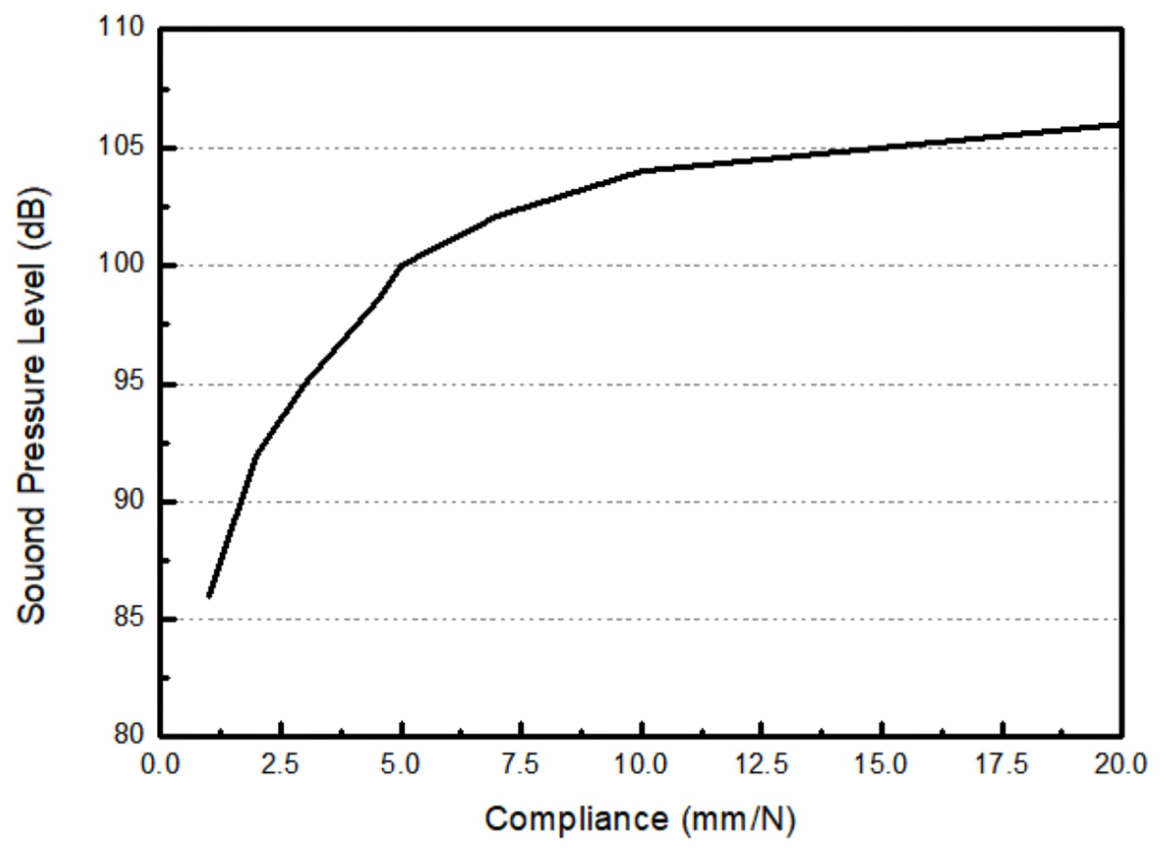
2.2. Enclosed-Field Acoustics Analysis
2.3. Simulation of Piezoelectric Microspeaker
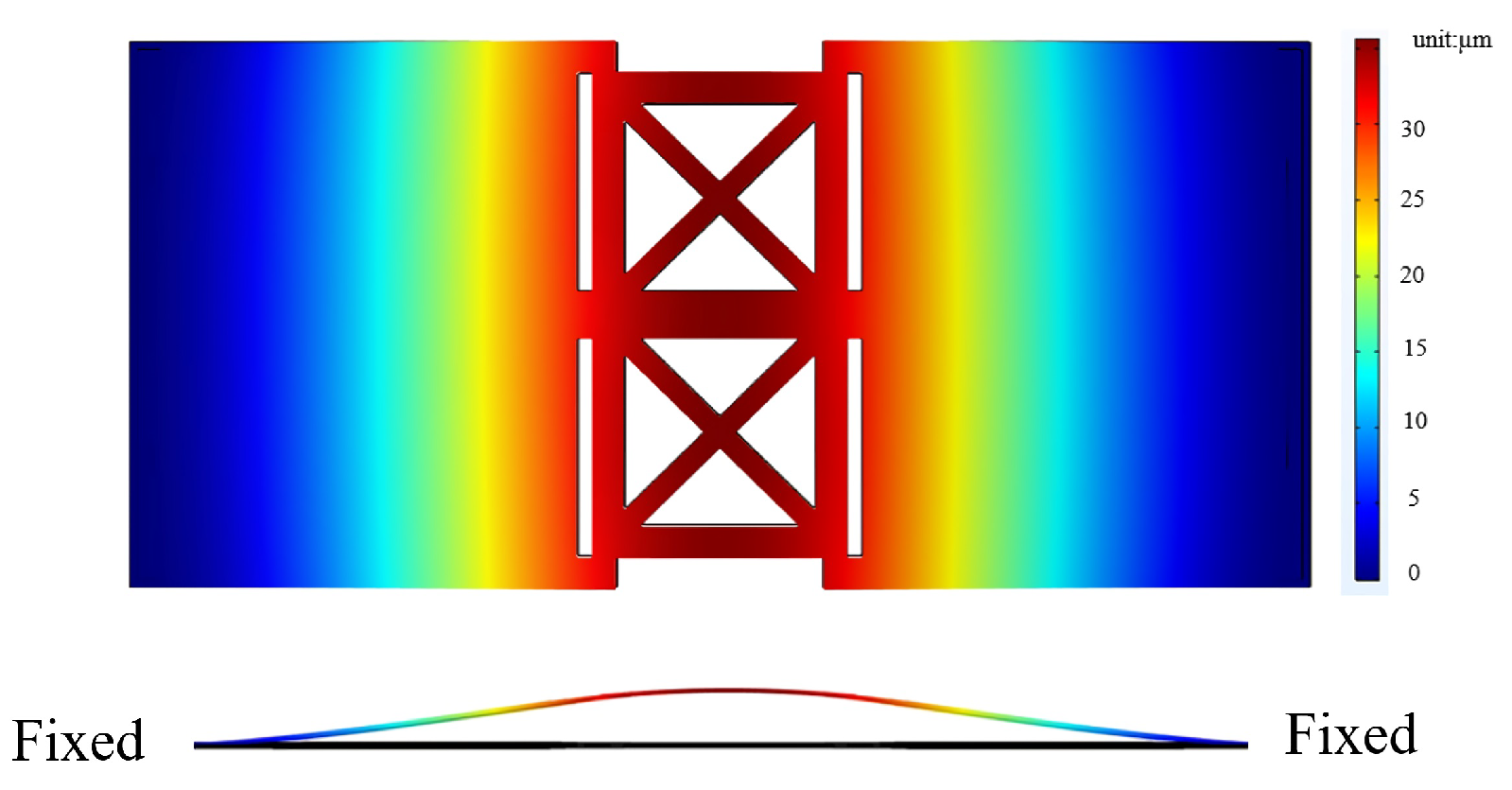
2.3.1. Substrate Structural Design
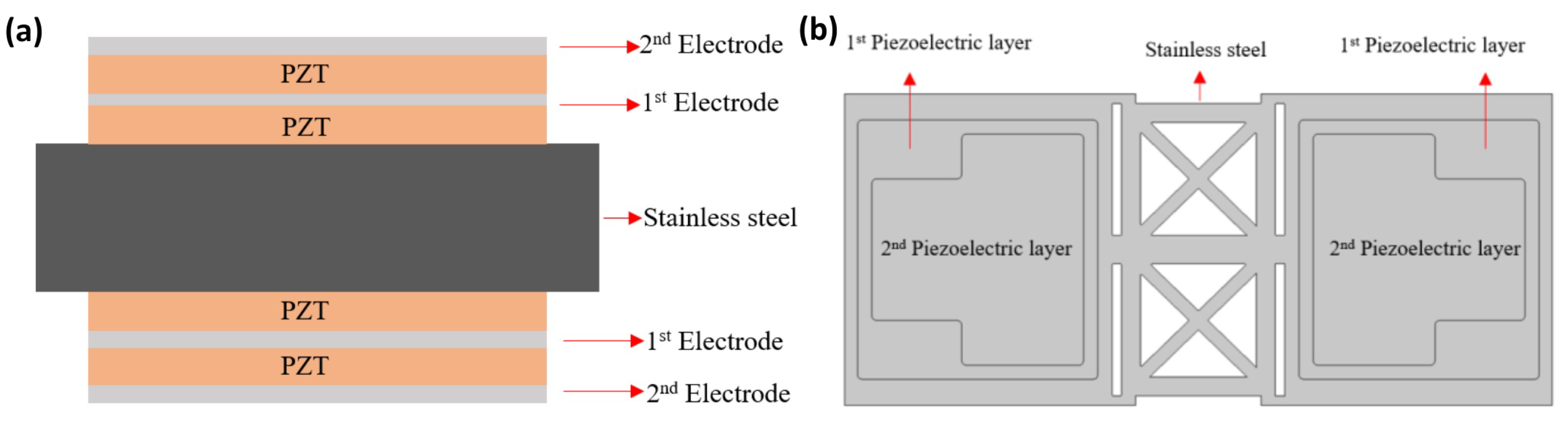
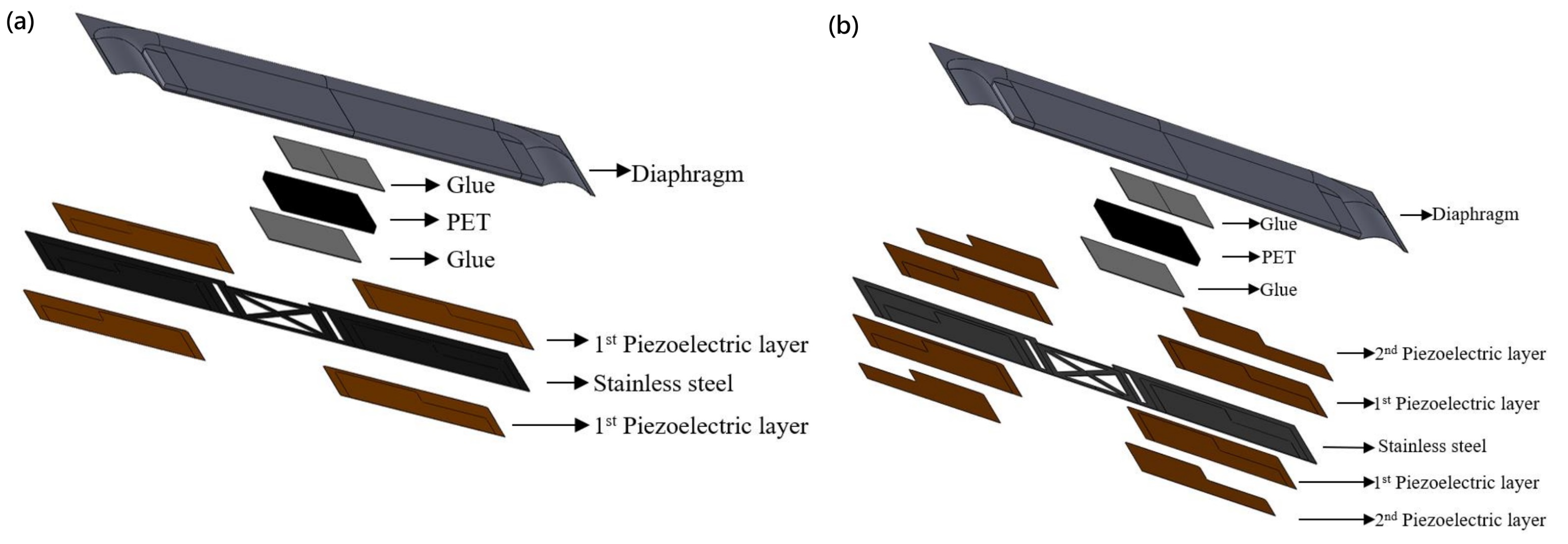
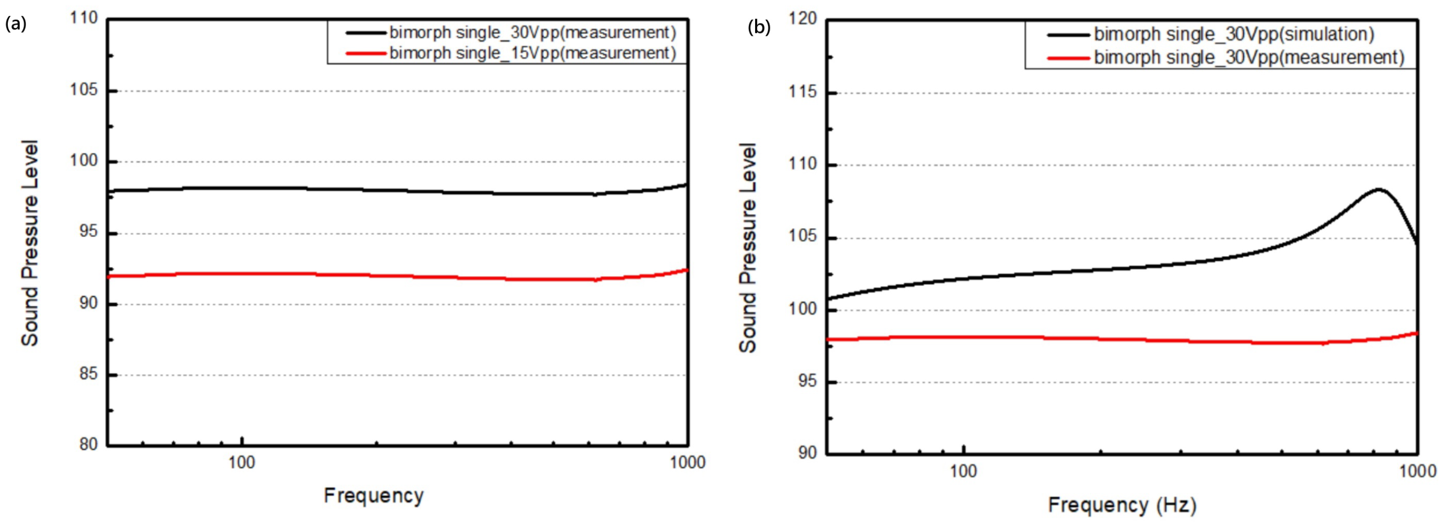
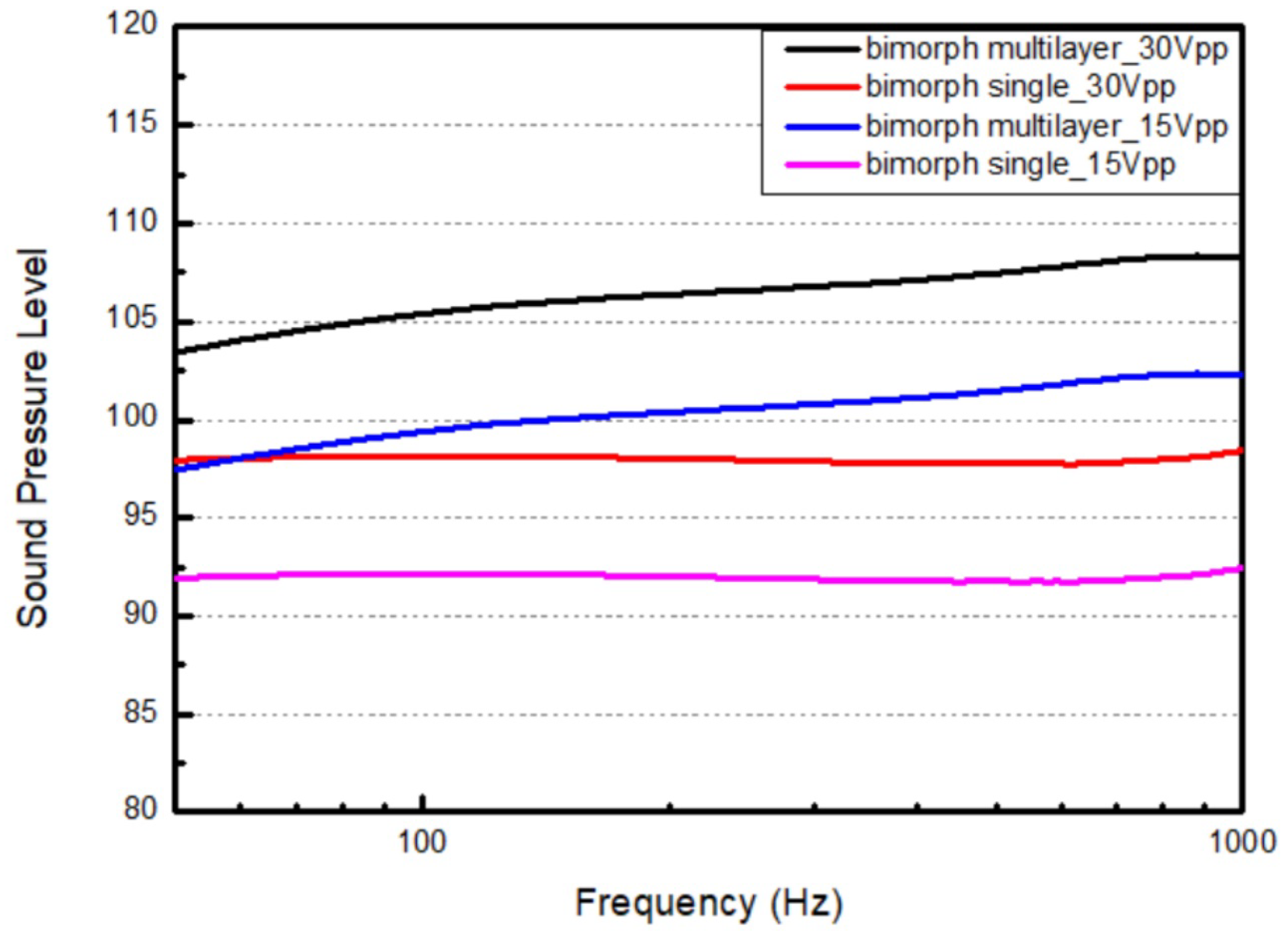
2.3.2. Bimorph Single-Layer Configuration
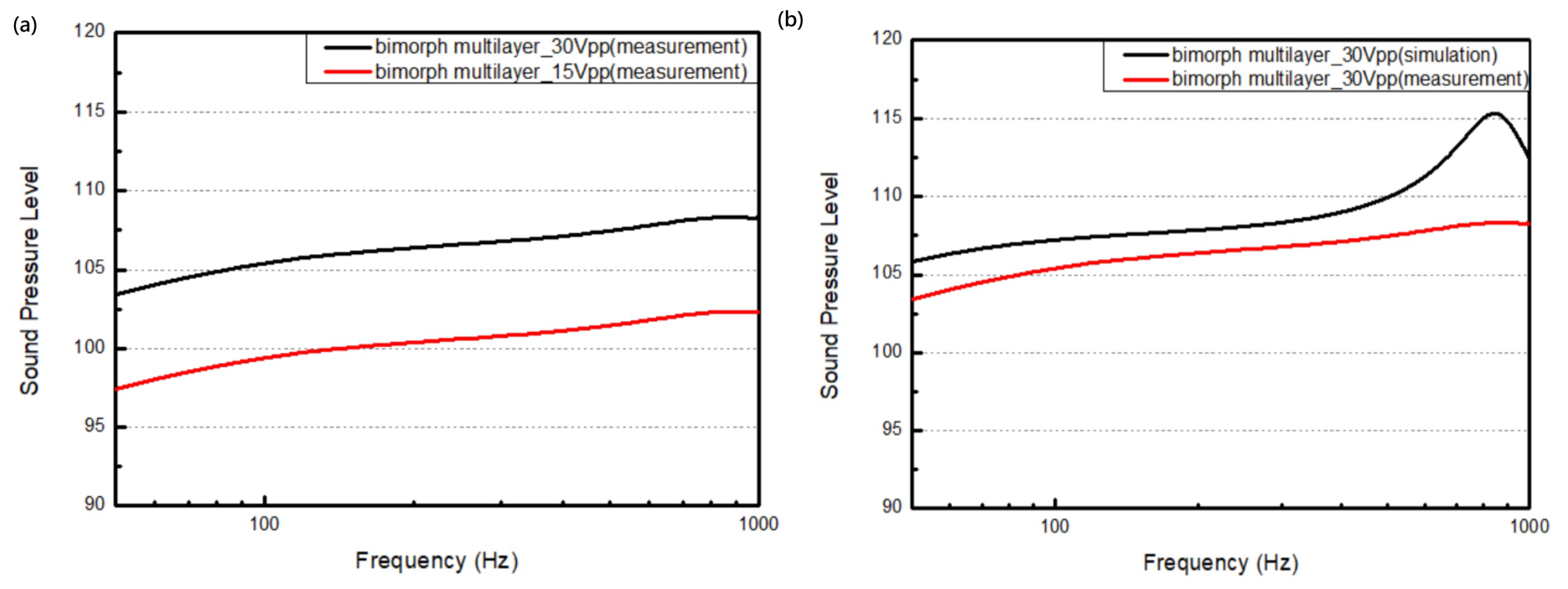
2.3.3. Bimorph Multi-Layer Configuration
2.4. Acoustic Analysis of Piezoelectric Microspeaker
3. Microspeaker Fabrication Process
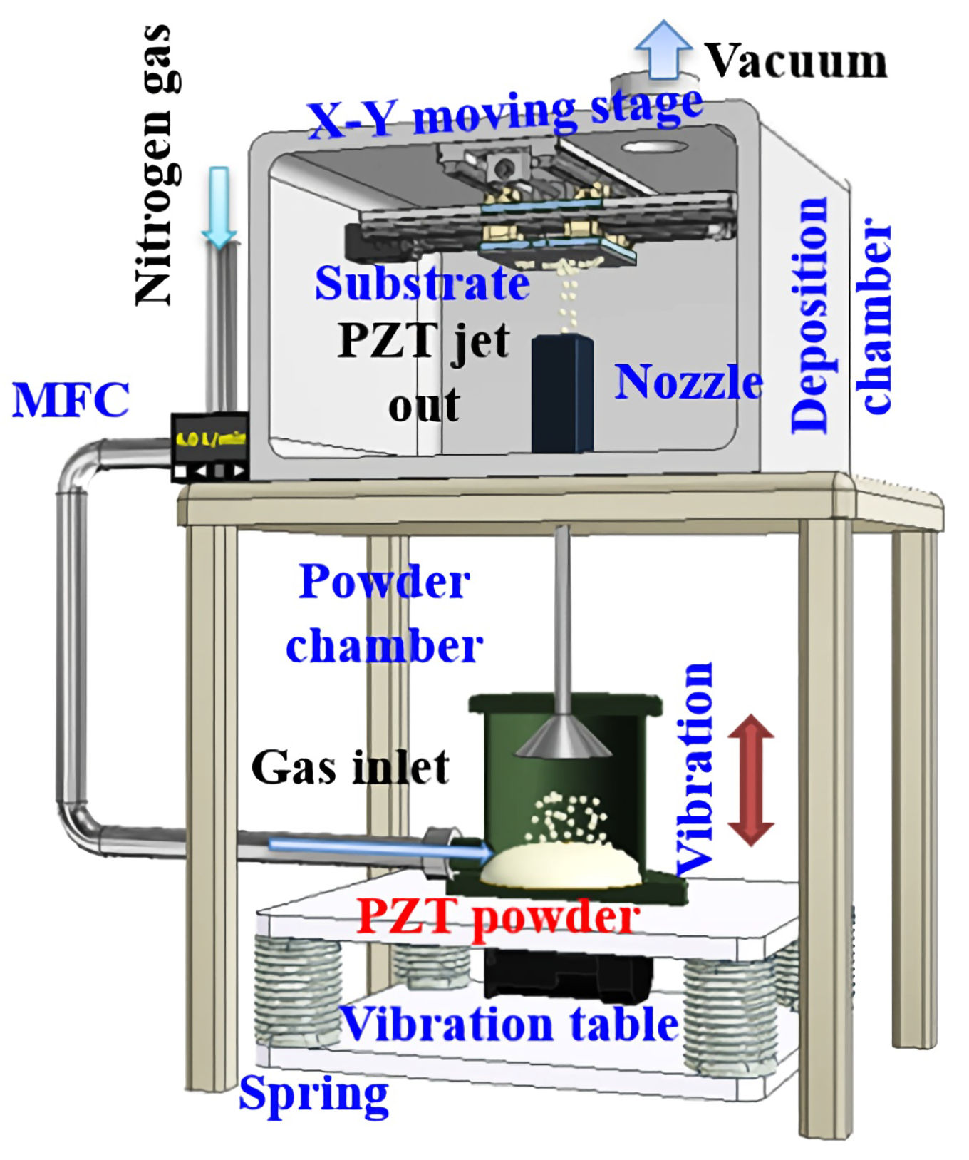
3.1. Aerosol Deposition Method
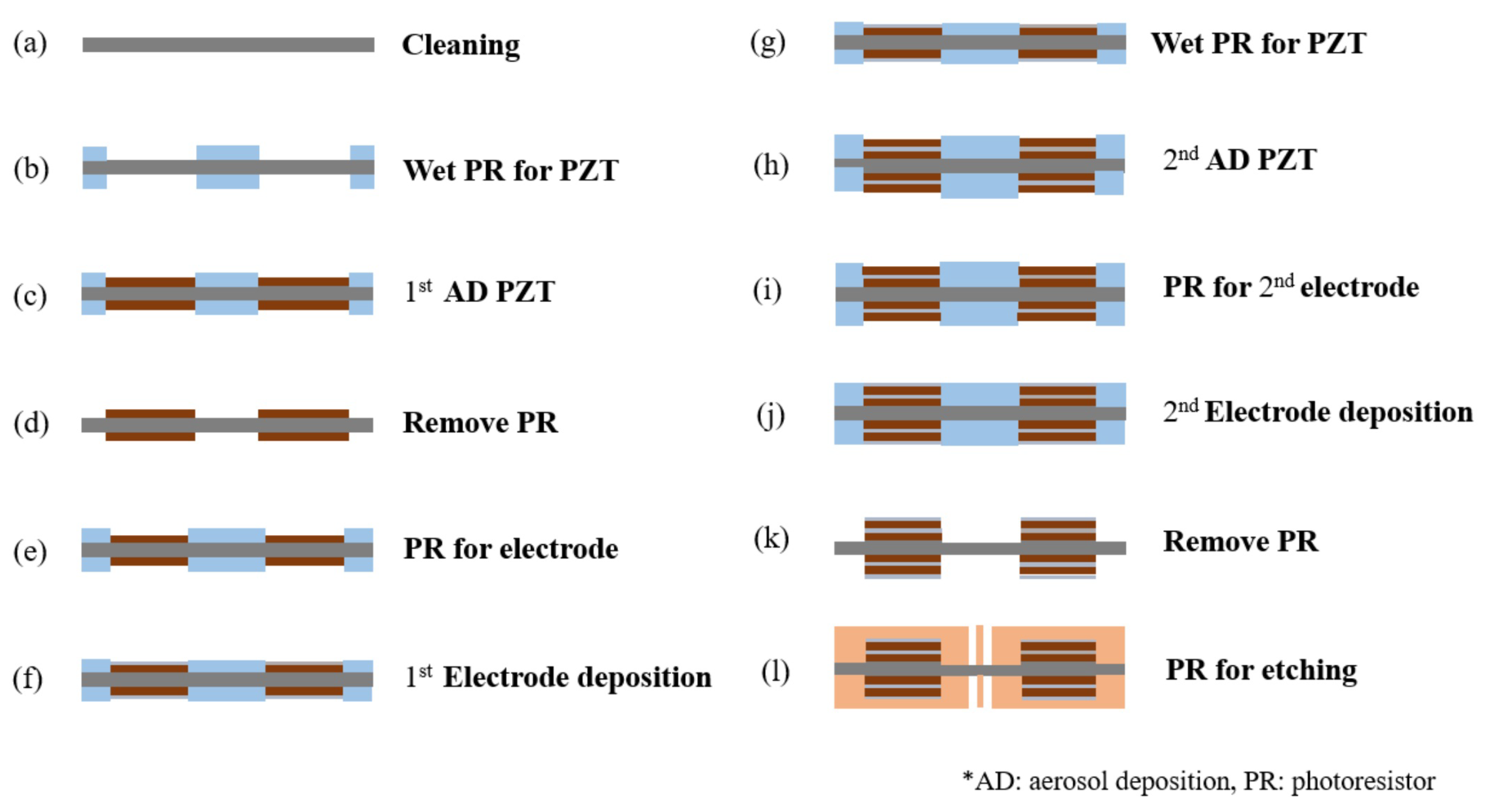
3.2. Metal Micro-Electrical–Mechanical System (MEMS) Process
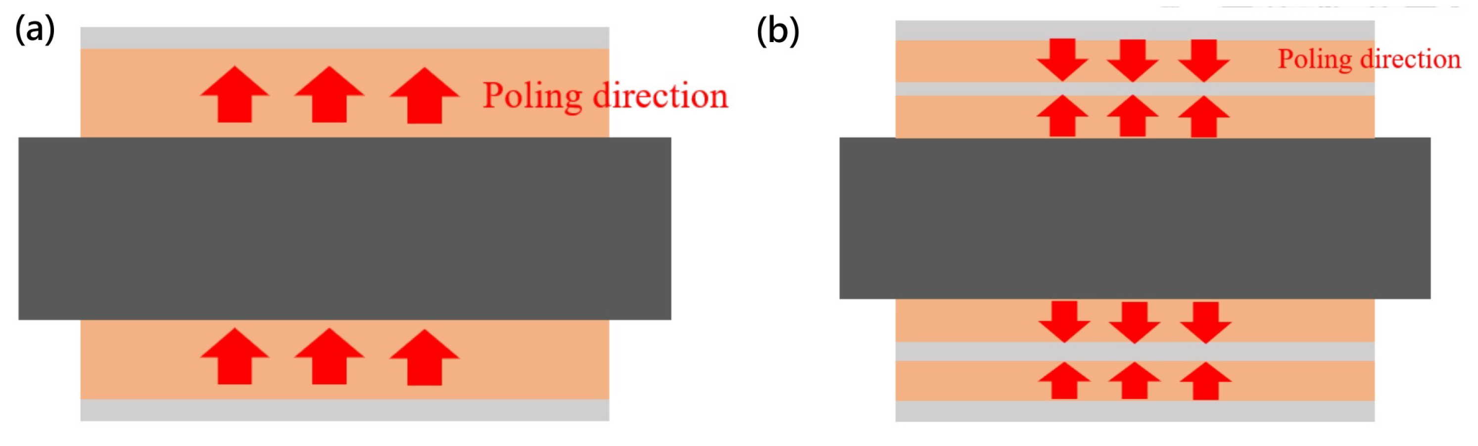
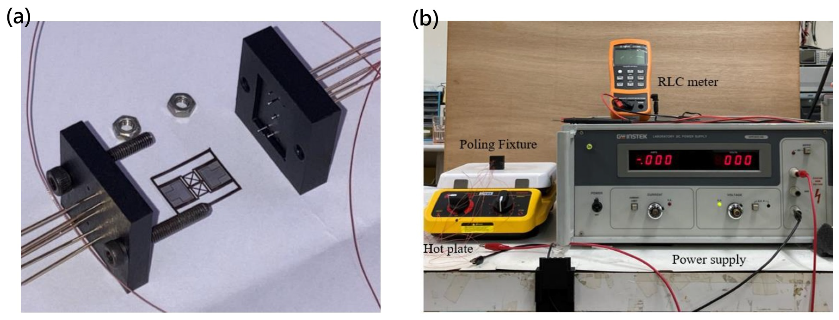
3.3. Annealing and Poling
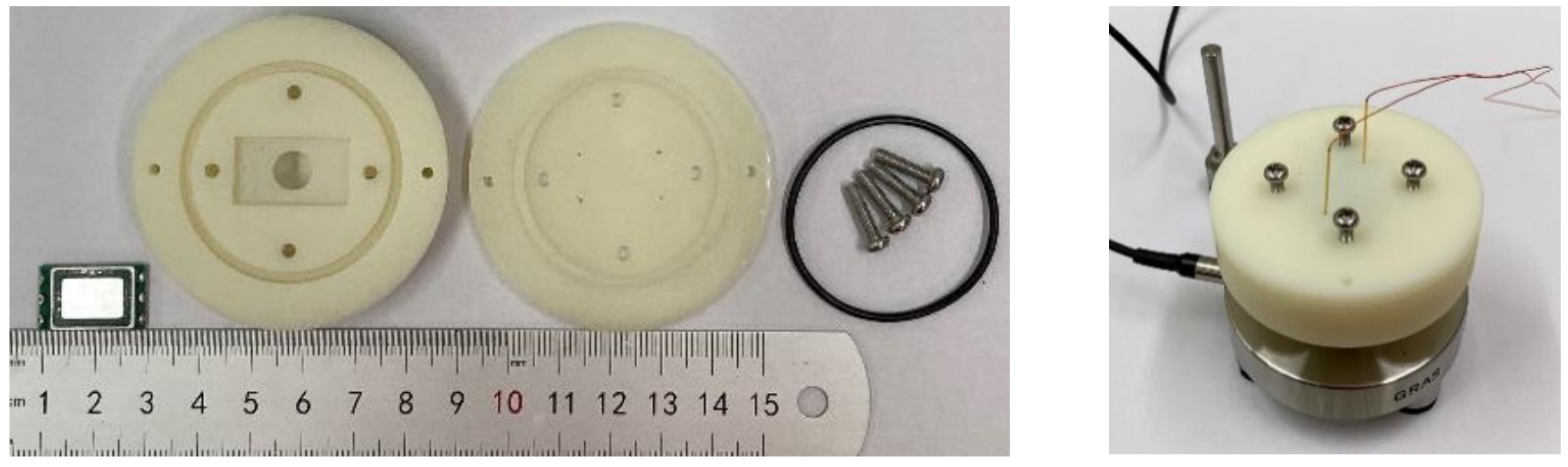
3.4. Packaging
4. Results and Discussion
5. Conclusions
6. Patents
Author Contributions
Funding
Data Availability Statement
Acknowledgments
Conflicts of Interest
References
- Status of the MEMS Industry 2021. Available online: https://medias.yolegroup.com/uploads/2021/07/YINTR21180-Status-of-the-MEMS-Industry-2021_Sample.pdf (accessed on 22 August 2022).
- Microphones, Microspeakers, and Audio Processing 2021 Report. Available online: https://www.yolegroup.com/product/report/microphones-microspeakers-and-audio-processing-2021/ (accessed on 25 August 2022).
- Cheng, M.-C.; Huang, W.-S.; Huang, S.R.-S. A silicon microspeaker for hearing instruments. J. Micromech. Microeng. 2004, 14, 859. [Google Scholar] [CrossRef]
- Harradine, M.; Birch, T.; Stevens, J.; Shearwood, C. A micro-machined loudspeaker for the hearing impaired. In Proceedings of the International Solid State Sensors and Actuators Conference (Transducers’ 97), Chicago, IL, USA, 10–16 June 1997. [Google Scholar]
- Je, S.-S.; Wang, N.; Brown, H.C.; Arnold, D.P.; Chae, J. An electromagnetically actuated microspeaker with fully-integrated wax-bonded Nd-Fe-B micromagnets for hearing aid applications. In Proceedings of the TRANSDUCERS 2009-2009 International Solid-State Sensors, Actuators and Microsystems Conference, Denver, CO, USA, 21–25 June 2009. [Google Scholar]
- Lemarqu, G.; Ravaud, R.; Shahosseini, I.; Lemarqu, V.; Moulin, J.; Lefeuvre, E. MEMS electrodynamic loudspeakers for mobile phones. Appl. Acoust. 2012, 73, 379–385. [Google Scholar] [CrossRef]
- Rashedin, R.; Meydan, T.; Borza, F. Electromagnetic micro-actuator array for loudspeaker application. Sens. Actuators A Phys. 2006, 129, 118–120. [Google Scholar] [CrossRef]
- Setiarini, A.; Sugandi, G.; Wijayanto, Y.N.; Wiranto, G.; Manurung, R.V.; Hermida, I.D.P. A novel structure of electromagnetic mems speaker for hearing aid application. In Proceedings of the 2018 International Conference on Radar, Antenna, Microwave, Electronics, and Telecommunications (ICRAMET), Serpong, Indonesia, 1–2 November 2018. [Google Scholar]
- Chiang, H.-Y.; Huang, Y.-H. Vibration and sound radiation of an electrostatic speaker based on circular diaphragm. J. Acoust. Soc. Am. 2015, 137, 1714–1721. [Google Scholar] [CrossRef]
- Huang, Y.-H.; Chiang, H.-Y. Vibrational mode and sound radiation of electrostatic speakers using circular and annular diaphragms. J. Sound Vib. 2016, 371, 210–226. [Google Scholar] [CrossRef]
- Kaiser, B.; Langa, S.; Ehrig, L.; Stolz, M.; Schenk, H.; Conrad, H.; Schenk, H.; Schimmanz, K.; Schuffenhauer, D. Concept and proof for an all-silicon MEMS micro speaker utilizing air chambers. Microsyst. Nanoeng. 2019, 5, 43. [Google Scholar] [CrossRef]
- Roberts, R.C.; Du, J.; Ong, A.O.; Li, D.; Zorman, C.A.; Tien, N.C. Electrostatically driven touch-mode poly-SiC microspeaker. Sensors 2007, 284–287. [Google Scholar] [CrossRef]
- Tumpold, D.; Stark, M.; Euler-Rolle, N.; Kaltenbacher, M.; Jakubek, S. Linearizing an electrostatically driven MEMS speaker by applying pre-distortion. Sens. Actuators A Phys. 2015, 236, 289–298. [Google Scholar] [CrossRef]
- Zhou, Q.; Zettl, A. Electrostatic graphene loudspeaker. Appl. Phys. Lett. 2013, 102, 22. [Google Scholar] [CrossRef]
- Bobinger, M.; La Torraca, P.; Mock, J.; Becherer, M.; Cattani, L.; Angeli, D.; Larcher, L.; Lugli, P. Solution-processing of copper nanowires for transparent heaters and thermo-acoustic loudspeakers. IEEE Trans. Nanotechnol. 2018, 17, 940–947. [Google Scholar] [CrossRef]
- Fei, W.; Zhou, J.; Guo, W. Low-voltage Driven Graphene Foam Thermoacoustic Speaker. Small 2015, 11, 2252–2256. [Google Scholar] [CrossRef] [PubMed]
- Liu, Y.; Tong, L.; Lai, S.K. Thermo-acoustics generated by periodically heated thin line array. J. Sound Vib. 2018, 427, 28–40. [Google Scholar] [CrossRef]
- Wang, D.; He, X.; Zhao, J.; Jin, L.; Ji, X. Research on the electrical-thermal-acoustic conversion behavior of thermoacoustic speakers based on multilayer graphene film. IEEE Sens. J. 2020, 20, 14646–14654. [Google Scholar] [CrossRef]
- Casset, F.; Dejaeger, R.; Laroche, B.; Desloges, B.; Leclere, Q.; Morisson, R.; Bohard, Y.; Goglio, J.P.; Escato, J.; Fanget, S. A 256 MEMS membrane digital loudspeaker array based on PZT actuators. Procedia Eng. 2015, 120, 49–52. [Google Scholar] [CrossRef]
- Cheng, H.-H.; Huang, Z.-R.; Wu, M.; Fang, W. Low frequency sound pressure level improvement of piezoelectric MEMS microspeaker using novel spiral spring with dual electrode. In Proceedings of the 20th International Conference on Solid-State Sensors, Actuators and Microsystems & Eurosensors XXXIII (TRANSDUCERS & EUROSENSORS XXXIII), Berlin, Germany, 23–27 June 2019. [Google Scholar]
- Cho, I.-J.; Jang, S.; Nam, H.-J. A piezoelectrically actuated mems speaker with polyimide membrane and thin film pb (zr, ti) o3 (pzt) actuator. Integr. Ferroelectr. 2009, 105, 27–36. [Google Scholar] [CrossRef]
- Kim, H.; Yang, W. The effects of electrodes patterned onto the piezoelectric thin film on frequency response characteristics of PMN-PT MEMS acoustic actuators. J. Electroceram. 2015, 35, 45–52. [Google Scholar] [CrossRef]
- Ko, S.C.; Kim, Y.C.; Lee, S.S.; Choi, S.H.; Kim, S.R. Micromachined piezoelectric membrane acoustic device. Sens. Actuators A Phys. 2003, 103, 130–134. [Google Scholar] [CrossRef]
- Seo, K.; Park, J.; Kim, H.; Kim, D.; Ur, S.; Yi, S. Micromachined piezoelectric microspeakers fabricated with high quality AlN thin film. Integr. Ferroelectr. 2007, 95, 74–82. [Google Scholar] [CrossRef]
- Stoppel, F.; Eisermann, C.; Gu-Stoppel, S.; Kaden, D.; Giese, T.; Wagner, B. Novel membrane-less two-way MEMS loudspeaker based on piezoelectric dual-concentric actuators. In Proceedings of the 19th International Conference on Solid-State Sensors, Actuators and Microsystems (TRANSDUCERS), Kaohsiung, Taiwan, 18–22 June 2017. [Google Scholar]
- Yi, S.; Ur, S.C.; Kim, E.S. Performance of packaged piezoelectric microspeakers depending on the material properties. In Proceedings of the IEEE 22nd International Conference on Micro Electro Mechanical Systems, Sorrento, Italy, 25–29 January 2009. [Google Scholar]
- ADAP UT-P2017 Specification. Available online: https://www.usound.com/wp-content/uploads/2019/05/2019-05_Adap_UT-P-2017_Datasheet.pdf (accessed on 16 October 2023).
- IEC 60318-4; Electroacoustics—Simulators of Human Head and Ear, Edition 1.0. IEC: Geneva, Switzerland, 2010.
- Wille, M.; Rasmussen, P. IEC 60318-4 ear simulator for low noise measurements & anthropometric rubber pinna. In Proceedings of the Audio Engineering Society Conference: 2016 AES International Conference on Headphone Technology, Aalborg, Denmark, 24–26 August 2016. [Google Scholar]
- Lin, S.C.; Wu, W.J. Fabrication of PZT MEMS energy harvester based on silicon and stainless-steel substrates utilizing an aerosol deposition method. J. Micromech. Microeng. 2013, 23, 125028. [Google Scholar] [CrossRef]
- Kuo, C.L.; Lin, S.C.; Wu, W.J. Fabrication and performance evaluation of a metal-based bimorph piezoelectric MEMS generator for vibration energy harvesting. Smart Mater. Struct. 2016, 25, 105016. [Google Scholar] [CrossRef]
- Kuo, Y.C.; Chien, J.T.; Shih, W.T.; Chen, C.T.; Lin, S.C.; Wu, W.J. The fatigue behavior study of micro piezoelectric energy harvester under different working temperature. In Proceedings of the SPIE 10967, Active and Passive Smart Structures and Integrated Systems XIII, Denver, CO, USA, 3–9 March 2019; Volume 10967, pp. 667–672. [Google Scholar]
- Gong, X.; Kuo, Y.C.; Zhou, G.; Wu, W.J.; Liao, W.H. An aerosol deposition based MEMS piezoelectric accelerometer for low noise measurement. Microsyst. Nanoeng. 2023, 9, 23. [Google Scholar] [CrossRef]
- Kim, W.; Jang, G.-W.; Kim, Y.Y. Microspeaker diaphragm optimization for widening the operating frequency band and increasing sound pressure level. IEEE Trans. Magn. 2009, 46, 59–66. [Google Scholar] [CrossRef]
- Wang, H.; Chen, Z.; Xie, H. A high-SPL piezoelectric MEMS loud speaker based on thin ceramic PZT. Sens. Actuators A Phys. 2020, 309, 112018. [Google Scholar] [CrossRef]


| Parameter | Single Bimorph Layer | Multiple Bimorph Layers |
|---|---|---|
| Stainless Steel Thickness | 30 µm | 30 µm |
| Stainless Steel Dimension | 12 × 6.8 mm2 | 12 × 6.8 mm2 |
| No. of Piezoelectric Layer | 2 | 4 |
| Piezoelectric Film Thickness per Layer | 10 µm | 5 µm |
| Total Piezoelectric Film Thickness | 20 µm | 20 µm |
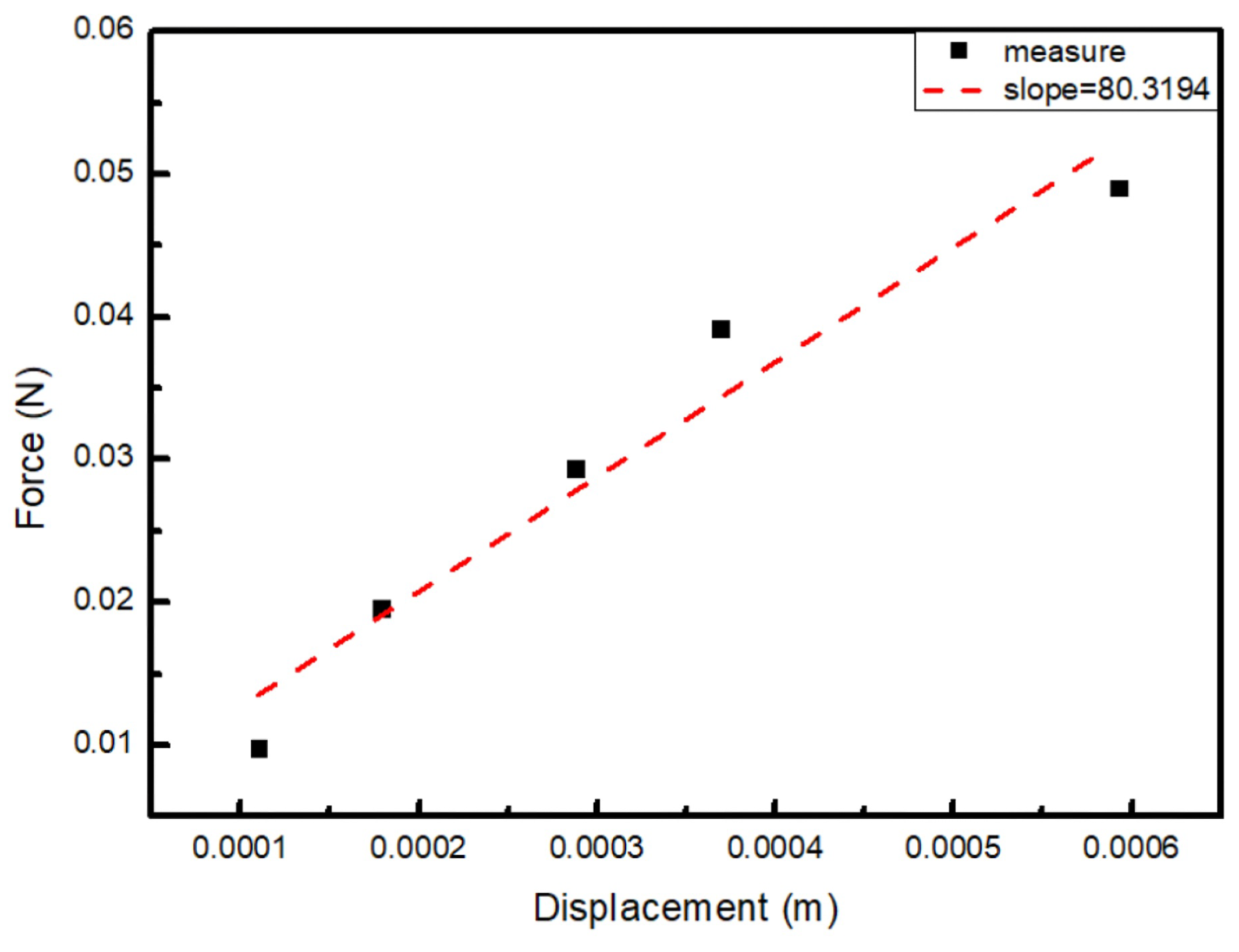
| Weight (g) | Force (N) | Displacement (m) | k (N/m) | Compliance (mm/N) |
|---|---|---|---|---|
| 1 | 0.00981 | 0.000110 | 89.29 | 11.2 |
| 2 | 0.01962 | 0.000179 | 109.89 | 9.1 |
| 3 | 0.02943 | 0.000288 | 102.05 | 9.8 |
| 4 | 0.03924 | 0.000369 | 106.38 | 9.4 |
| 5 | 0.04905 | 0.000593 | 82.67 | 12.1 |
| Reference | Material | Piezo-Layer Thickness | Diaphragm Size | Maximum SPL | Distance | Driving Voltage |
|---|---|---|---|---|---|---|
| Fully MEMS (without diaphragm) | ||||||
| [20] | Sputter PZT | 1 µm | mm2 | 106.8 dB @ 1.85 kHz | a | 15 Vpp |
| [23] | ZnO | 0.5 µm | mm2 | 83.1 dB @ 13.3 kHz | 10 mm | 30 Vpp |
| [24] | AlN | 0.5 µm | mm2 | 100 dB @ 10.0 kHz | 3 mm | 20 Vpp |
| [25] | Sol–gel PZT | 2 µm | mm2 | 110 dB | a | 20 Vpp |
| [35] | Ceramic PZT | 5 µm | 6 mm | 119 dB @ 9 kHz | 10 mm | 10 Vpp |
| Piezoelectric Actuated (with diaphragm) | ||||||
| [27] | Unknown | Unknown | mm2 | 52 dB @ 1 kHz | b | 15 VDC +15 Vpp |
| This work (BSL) c | Aerosol PZT | 20 µm | mm2 | 98.4 dB @ 830.2 Hz | a | 30 Vpp |
| This work (BML) d | Aerosol PZT | 20 µm | mm2 | 108.1 dB @ 895.4 Hz | a | 30 Vpp |
Disclaimer/Publisher’s Note: The statements, opinions and data contained in all publications are solely those of the individual author(s) and contributor(s) and not of MDPI and/or the editor(s). MDPI and/or the editor(s) disclaim responsibility for any injury to people or property resulting from any ideas, methods, instructions or products referred to in the content. |
© 2025 by the authors. Licensee MDPI, Basel, Switzerland. This article is an open access article distributed under the terms and conditions of the Creative Commons Attribution (CC BY) license (https://creativecommons.org/licenses/by/4.0/).
Share and Cite
Shih, W.-T.; Tsou, W.-H.; Vasic, D.; Costa, F.; Wu, W.-J. The Woofer-Type Piezo-Actuated Microspeaker Based on Aerosol Deposition and Metal MEMS Process. Micromachines 2025, 16, 353. https://doi.org/10.3390/mi16030353
Shih W-T, Tsou W-H, Vasic D, Costa F, Wu W-J. The Woofer-Type Piezo-Actuated Microspeaker Based on Aerosol Deposition and Metal MEMS Process. Micromachines. 2025; 16(3):353. https://doi.org/10.3390/mi16030353
Chicago/Turabian StyleShih, Wei-Ting, Wan-Hsin Tsou, Dejan Vasic, François Costa, and Wen-Jong Wu. 2025. "The Woofer-Type Piezo-Actuated Microspeaker Based on Aerosol Deposition and Metal MEMS Process" Micromachines 16, no. 3: 353. https://doi.org/10.3390/mi16030353
APA StyleShih, W.-T., Tsou, W.-H., Vasic, D., Costa, F., & Wu, W.-J. (2025). The Woofer-Type Piezo-Actuated Microspeaker Based on Aerosol Deposition and Metal MEMS Process. Micromachines, 16(3), 353. https://doi.org/10.3390/mi16030353