

Experiment of a Cut-Out Piezoelectric Beam Energy Harvester Under Wind-Induced Vibration


Abstract
1. Introduction
2. Experimental Program
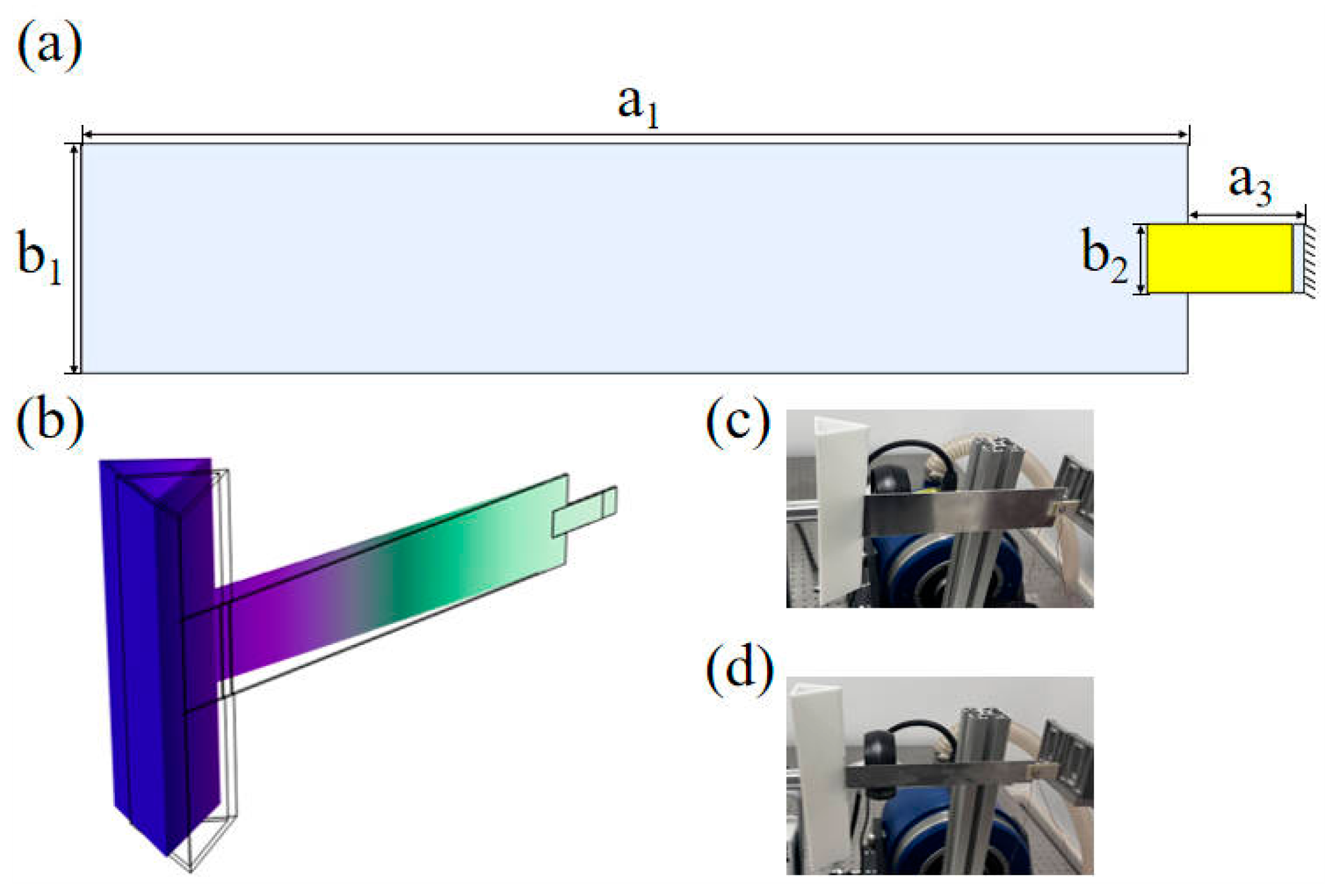
2.1. Experimental Model
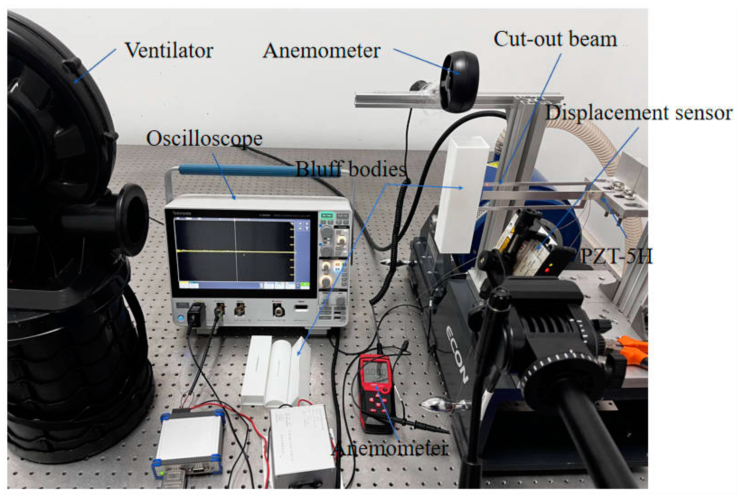
2.2. Experimental Configurations
3. Comparison and Analysis of Experimental Results
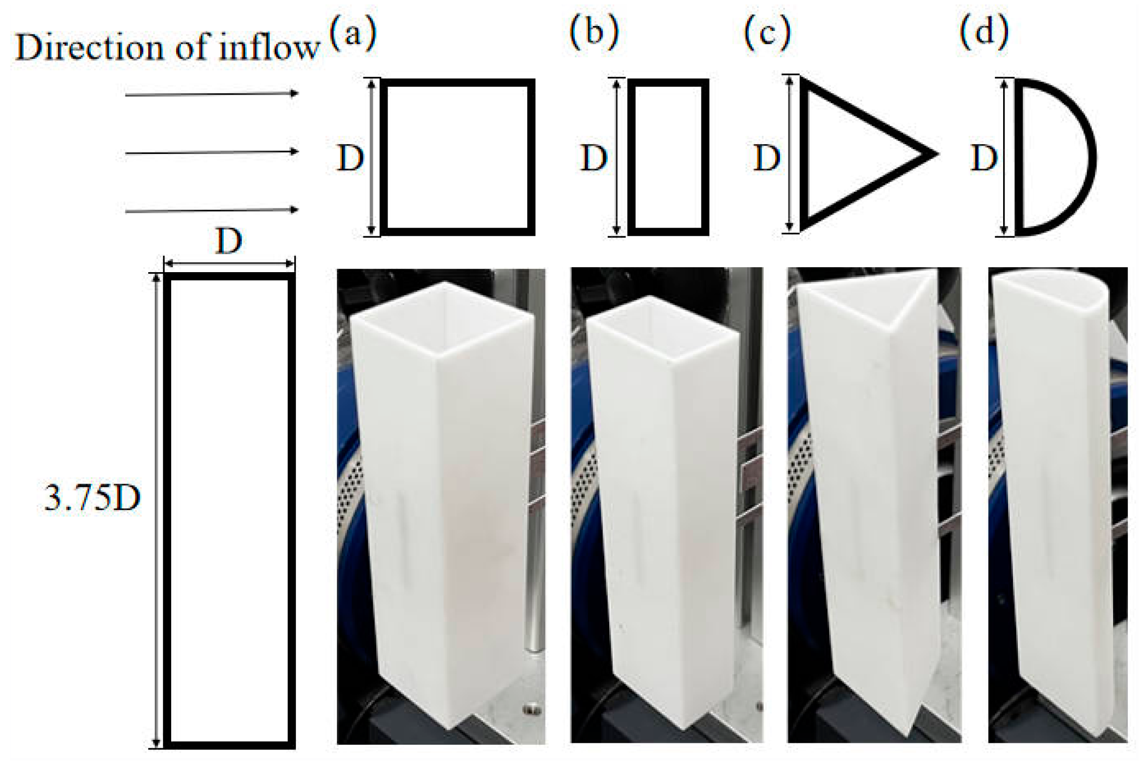
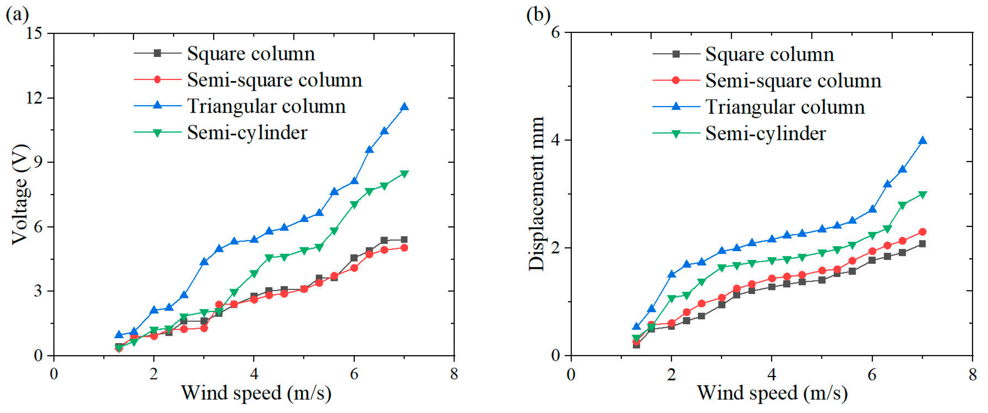
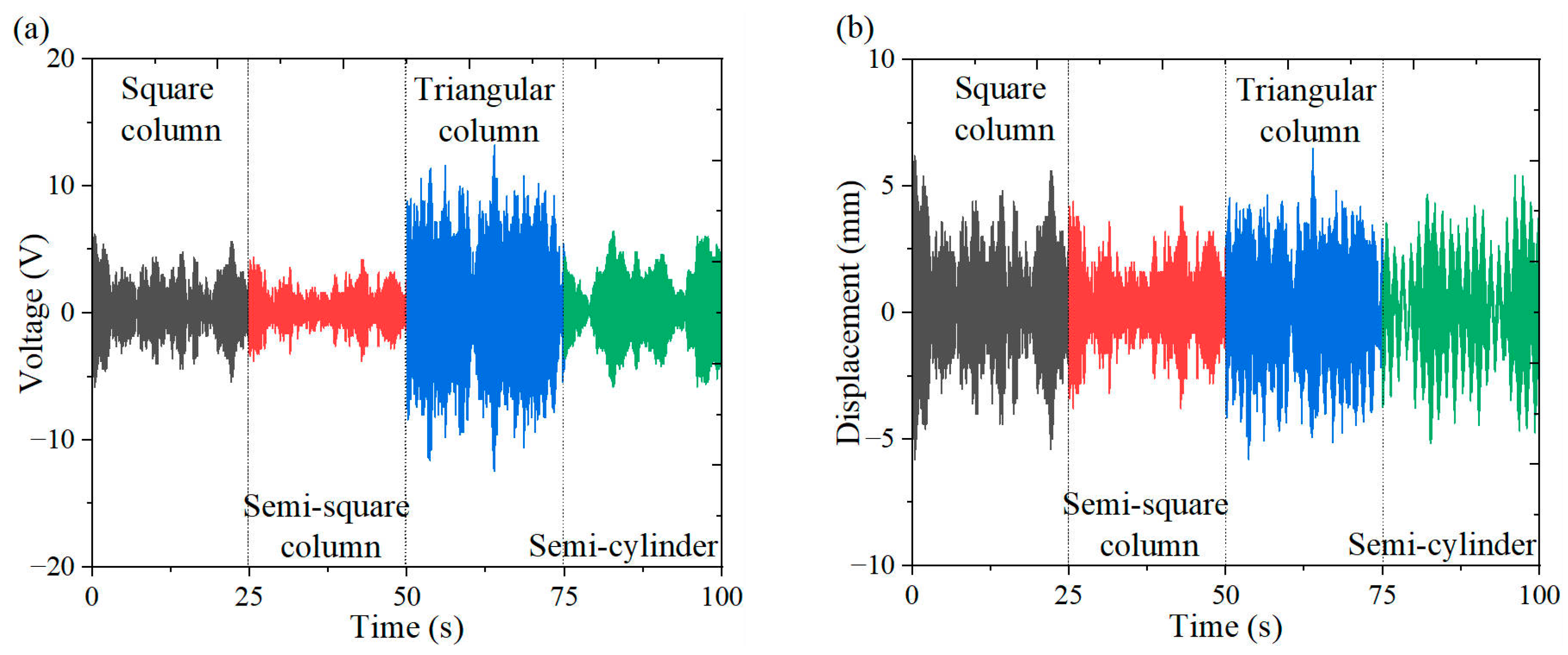
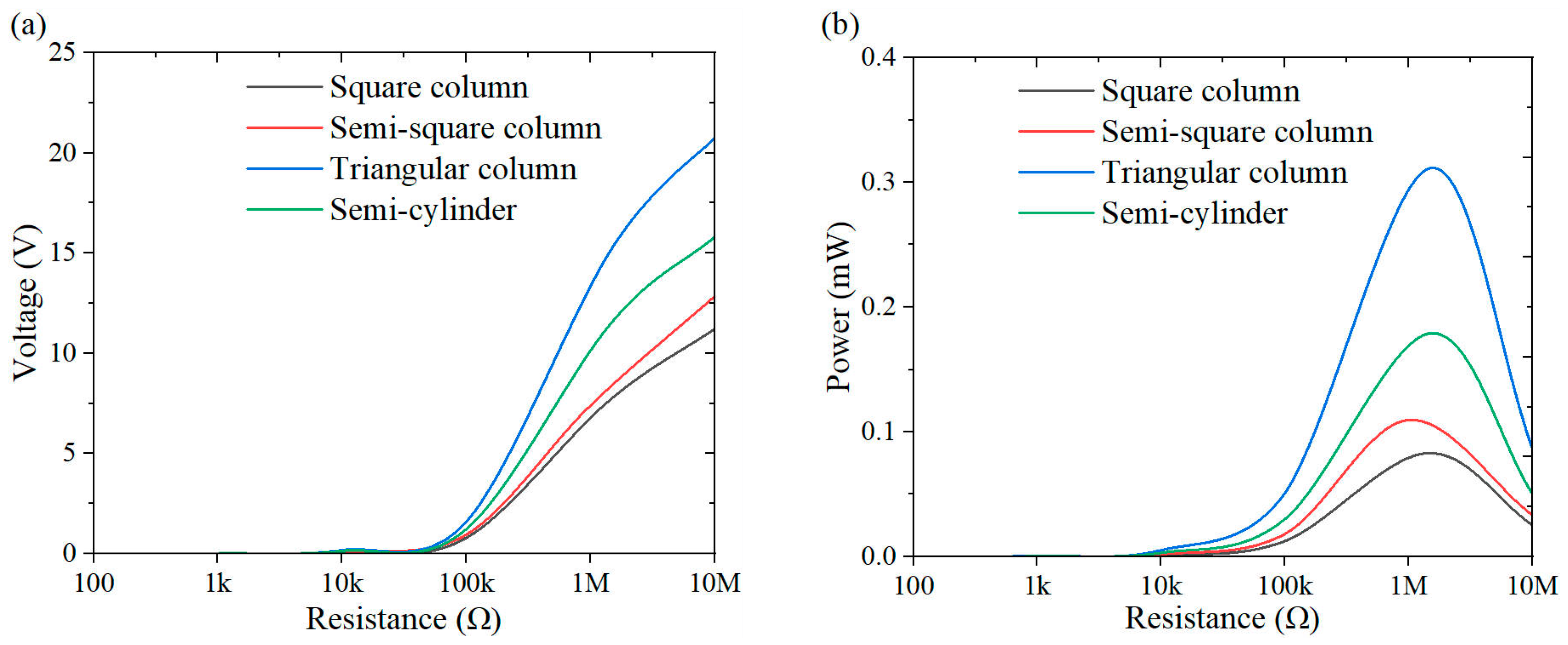
3.1. The Optimal Bluff Body
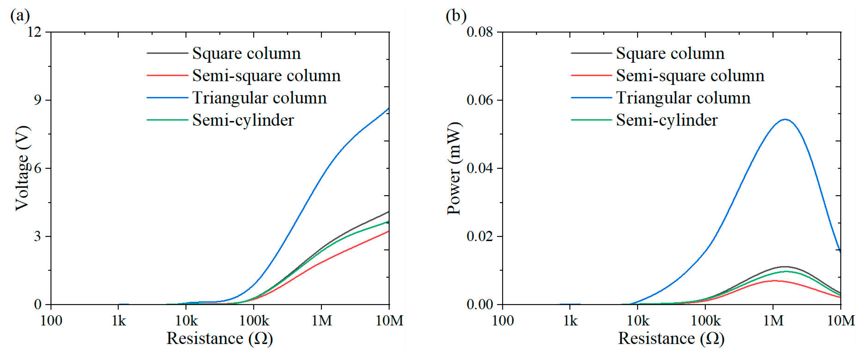
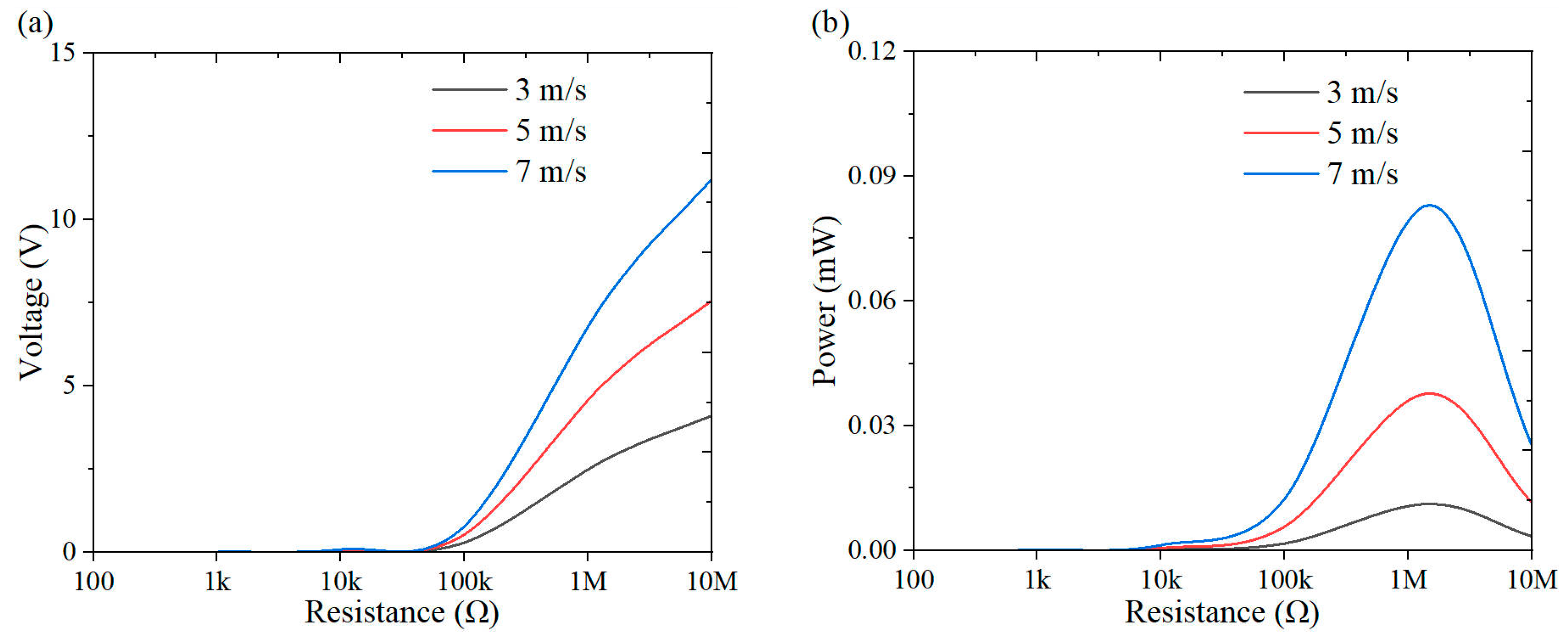
3.2. Power Output and Optimal Resistance
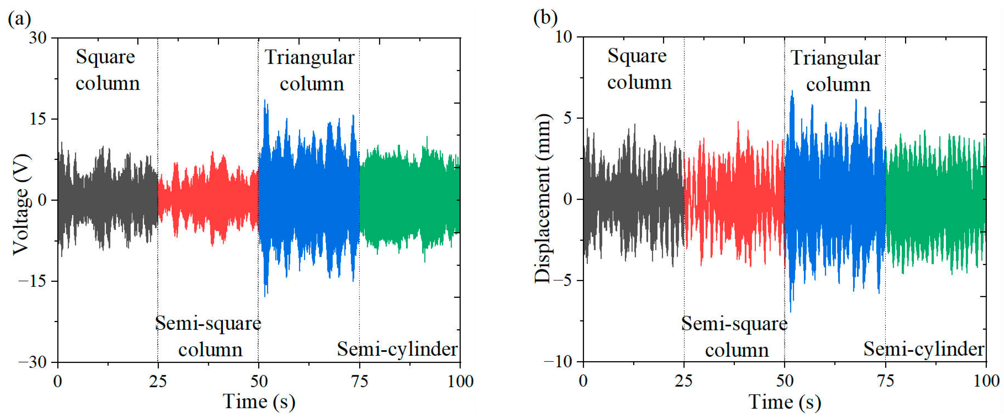
4. Comparative Analysis of Energy Harvesting Performance in Cut-Out and Non-Cut-Out Piezoelectric Beams Under a Triangular Column
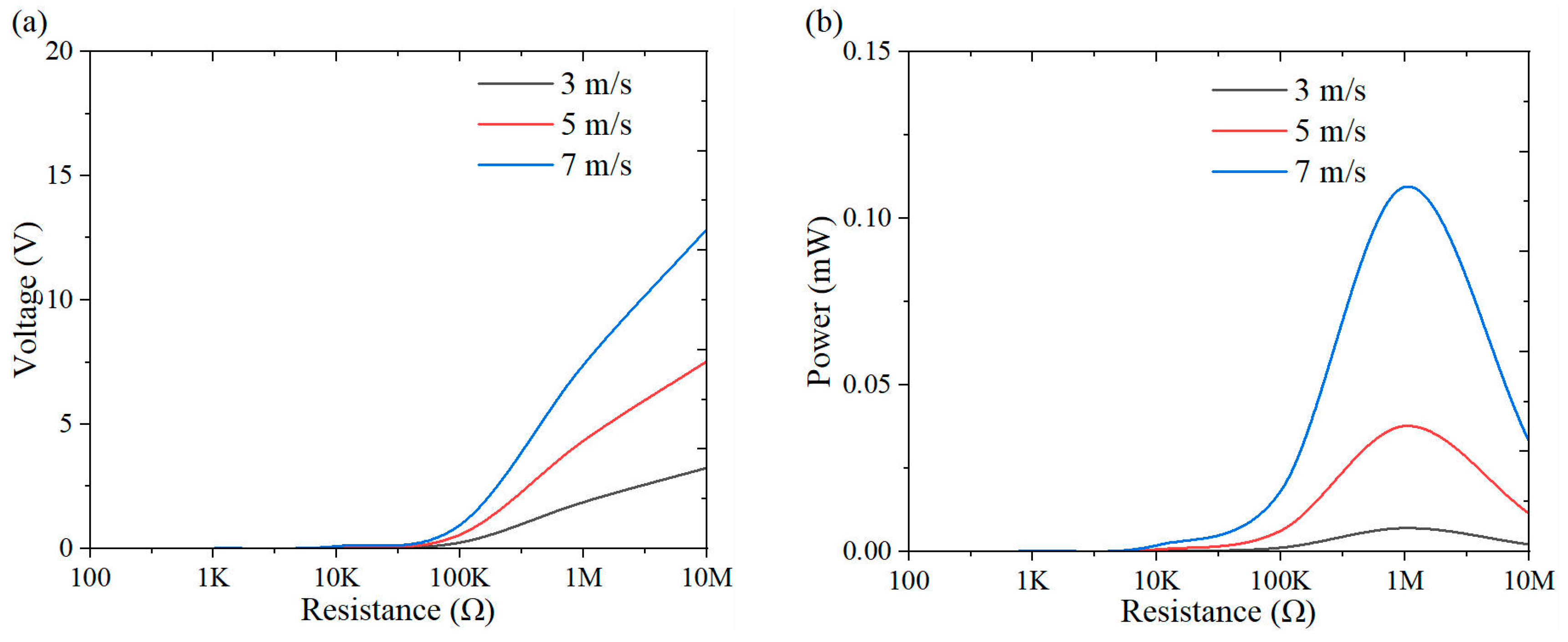
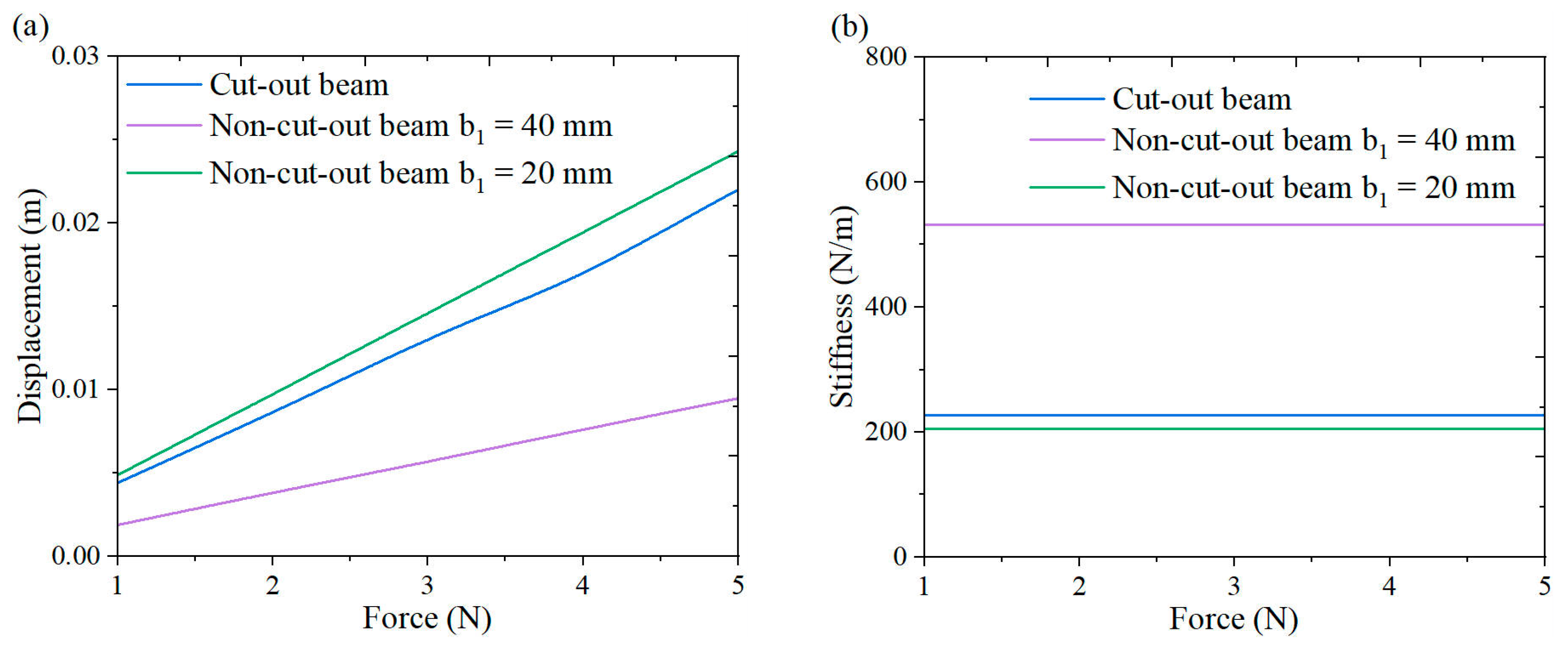
4.1. Non-Cut-Out Piezoelectric Beams Analysis
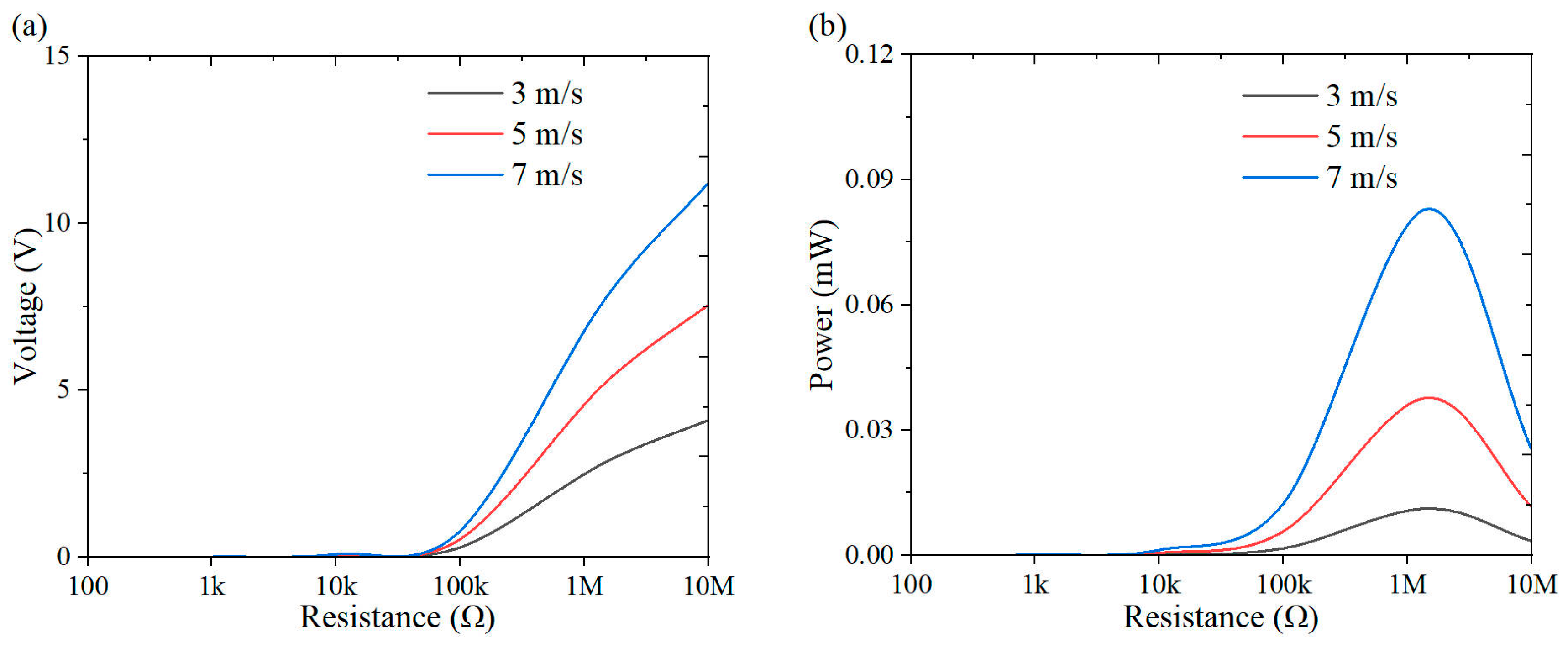
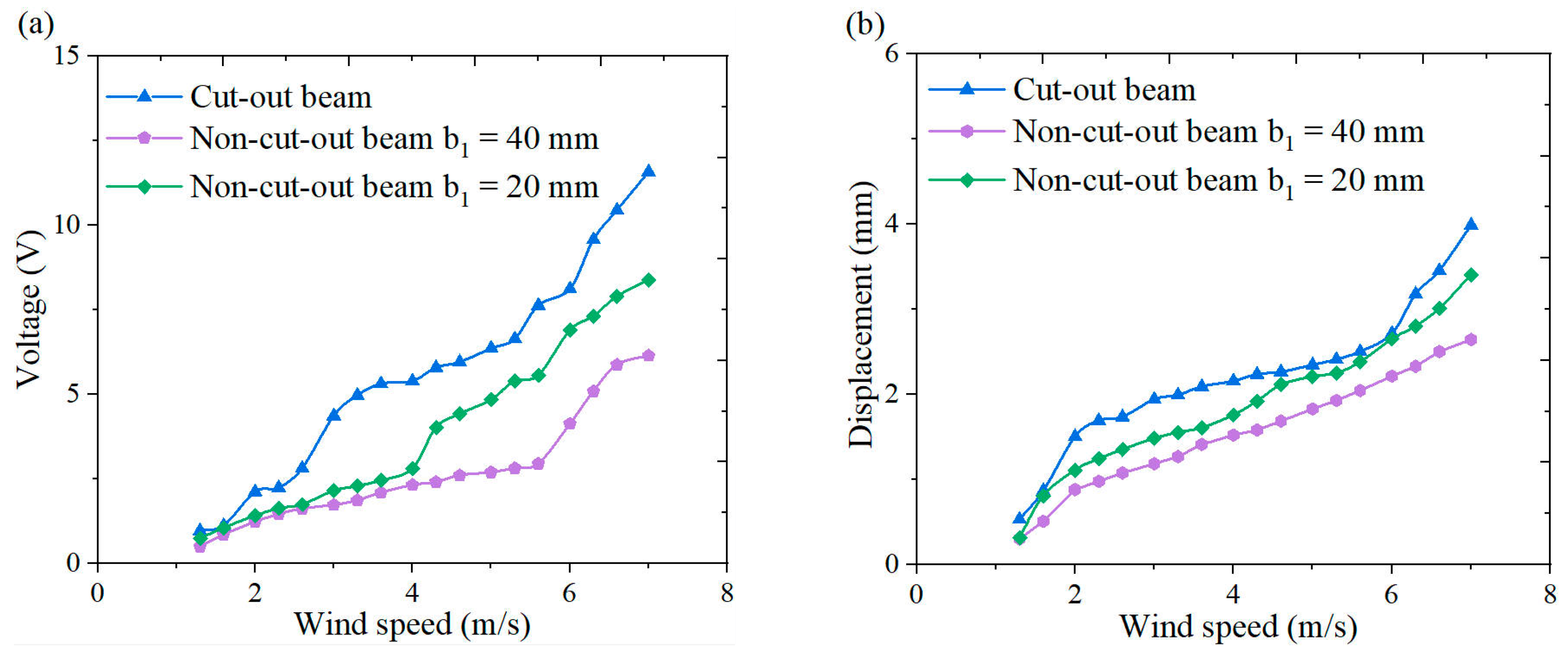
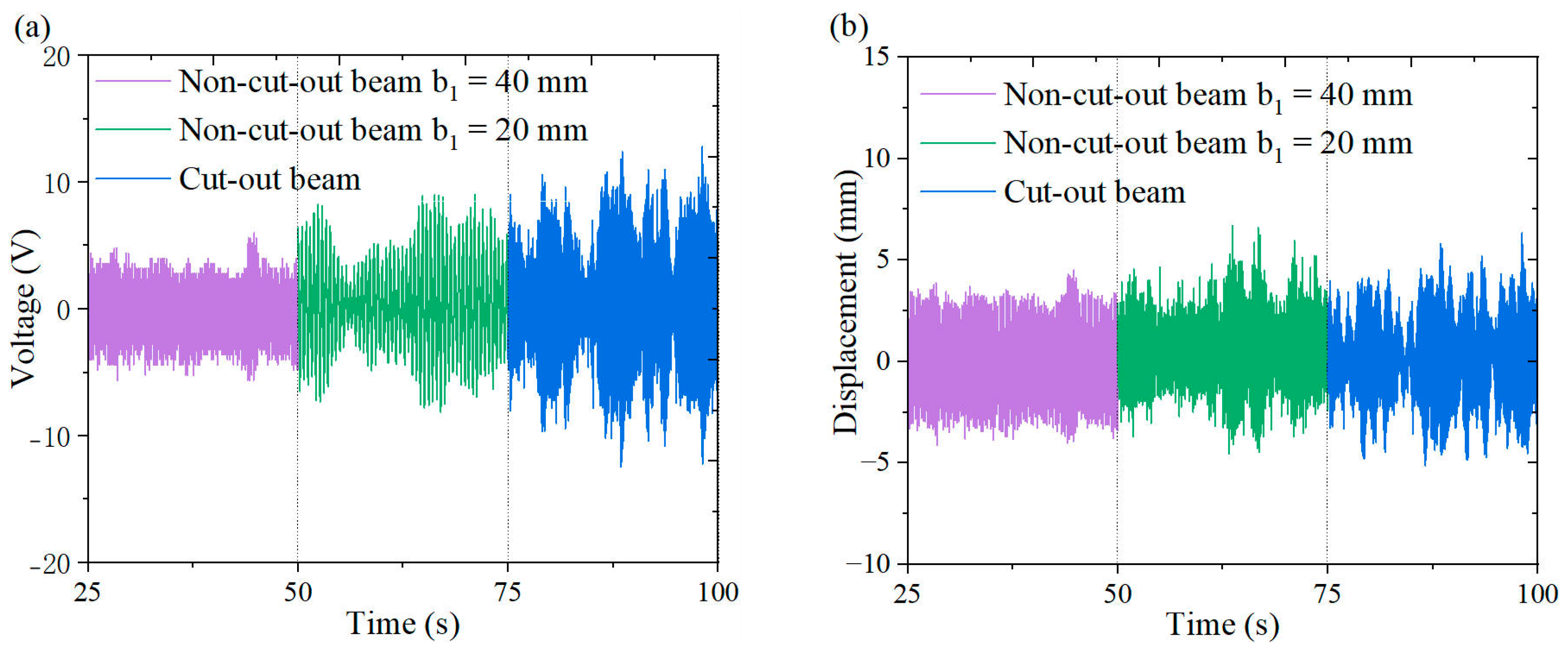
4.2. Experimental Results
5. Discussion
Author Contributions
Funding
Data Availability Statement
Conflicts of Interest
References
- International Energy Agency. Tracking SDG7: The Energy Progress Report; International Energy Agency: Paris, France, 2021.
- Statista. Internet of Things and Connected Devices Worldwide 2030; Statista: Hamburg, Germany, 2024. [Google Scholar]
- Sarker, M.R.; Saad, M.H.M.; Riaz, A.; Lipu, M.S.H.; Olazagoitia, J.L. Micro energy storage systems in energy harvesting applications: Analytical evaluation towards future research improvement. Micromachines 2022, 13, 512. [Google Scholar] [CrossRef] [PubMed]
- Mohsan, S.A.H.; Othman, N.Q.H.; Khan, M.A.; Amjad, H.; Żywiołek, J. A Comprehensive Review of Micro UAV Charging Techniques. Micromachines 2022, 13, 977. [Google Scholar] [CrossRef] [PubMed]
- Shehu, L.; Yeon, J.H.; Song, Y. Piezoelectric Energy Harvesting for Civil Engineering Applications. Energies 2024, 17, 4935. [Google Scholar] [CrossRef]
- Farhan, M.; Muthalif, A.G.; Ali, M.S.M. Innovative Approaches to Optimize Vibration Energy Harvesting (VEH): A Comprehensive Review. Energy Rep. 2024, 12, 5194–5219. [Google Scholar] [CrossRef]
- Bhatt, K.; Kumar, S.; Kumar, S.; Sharma, S.; Singh, V. A Review on Energy Harvesting Technologies: Comparison between Non-Conventional and Conceptual Approaches. Energy Rep. 2024, 12, 4717–4740. [Google Scholar] [CrossRef]
- Bakhtiar, S.; Khan, F.U.; Fu, H.; Hajjaj, A.Z.; Theodossiades, S. Fluid Flow-Based Vibration Energy Harvesters: A Critical Review of State-of-the-Art Technologies. Appl. Sci. 2024, 14, 11452. [Google Scholar] [CrossRef]
- Msigwa, G.; Ighalo, J.O.; Yap, P.S. Considerations on Environmental, Economic, and Energy Impacts of Wind Energy Generation: Projections towards Sustainability Initiatives. Sci. Total Environ. 2022, 849, 157755. [Google Scholar] [CrossRef] [PubMed]
- Wang, J.L.; Geng, L.F.; Ding, L.; Zhu, H.-J.; Yurchenko, D. The State-of-the-Art Review on Energy Harvesting from Flow-Induced Vibrations. Appl. Energy 2020, 267, 114902. [Google Scholar] [CrossRef]
- Wang, S.-Y.; Liao, W.-L.; Zhang, Z.-H.; Liao, Y.; Yan, M.-J.; Kan, J.-W. Development of a Novel Non-Contact Piezoelectric Wind Energy Harvester Excited by Vortex-Induced Vibration. Energy Convers. Manag. 2021, 235, 113980. [Google Scholar] [CrossRef]
- Liu, F.-R.; Zhao, L.-C.; Yan, G.; Zhang, W.-M.; Wu, Z.-Y.; Zhang, X.-L. Performing Magnetic Boundary Modulation to Broaden the Operational Wind Speed Range of a Piezoelectric Cantilever-Type Wind Energy Harvester. Micromachines 2024, 15, 1286. [Google Scholar] [CrossRef]
- Hasegawa, K.; Ueno, T.; Kiwata, T. Proposal of Wind Vibrational Power Generator Using Magnetostrictive Material. IEEE Trans. Magn. 2019, 55, 1–4. [Google Scholar] [CrossRef]
- Zheng, X.-T.; He, L.-P.; Wang, S.-J.; Liu, X.-J.; Liu, R.-W.; Cheng, G.-M. A Review of Piezoelectric Energy Harvesters for Harvesting Wind Energy. Sens. Actuators A Phys. 2023, 352, 114190. [Google Scholar] [CrossRef]
- Ma, X.-Q.; Zhou, S.-X. A Review of Flow-Induced Vibration Energy Harvesters. Energy Convers. Manag. 2022, 254, 115223. [Google Scholar] [CrossRef]
- Sun, W.; Wang, Y.-H.; Liu, Y.; Su, B.; Guo, T.; Cheng, G.-G.; Zhang, Z.-Q.; Ding, J.; Seok, J. Navigating the Future of Flow-Induced Vibration-Based Piezoelectric Energy Harvesting. Renew. Sustain. Energy Rev. 2024, 201, 114624. [Google Scholar] [CrossRef]
- Yang, Y.-W.; Zhao, L.-Y.; Tang, L.-H. Comparative Study of Tip Cross-Sections for Efficient Galloping Energy Harvesting. Appl. Phys. Lett. 2013, 102, 064105. [Google Scholar] [CrossRef]
- Yang, X.-K.; Xu, B.-K.; Shang, Z.-D.; Tian, J.-Y.; Cai, H.-C.; Hu, X.-Y. Effects of Aerodynamic Parameters on Performance of Galloping Piezoelectric Energy Harvester Based on Cross-Sectional Shape Evolutionary Approach. Micromachines 2025, 16, 254. [Google Scholar] [CrossRef]
- Kang, J.G.; Kim, H.; Shin, S.; Kim, B.S. Fluid Flow to Electricity: Capturing Flow-Induced Vibrations with Micro-Electromechanical-System-Based Piezoelectric Energy Harvester. Micromachines 2024, 15, 581. [Google Scholar] [CrossRef]
- Song, J.-W.; Sun, G.-H.; Zeng, X.; Li, X.-W.; Bai, Q.; Zheng, X.-J. Piezoelectric Energy Harvester with Double Cantilever Beam Undergoing Coupled Bending-Torsion Vibrations by Width-Splitting Method. Sci. Rep. 2022, 12, 583. [Google Scholar] [CrossRef]
- He, X.-F.; Yang, X.-K.; Jiang, S.-L. Enhancement of Wind Energy Harvesting by Interaction Between Vortex-Induced Vibration and Galloping. Appl. Phys. Lett. 2018, 112, 033901. [Google Scholar] [CrossRef]
- Wu, T.-Y.; Jiang, W.-A.; Chen, L.-Q.; Bi, Q.-S. A Broadband Flow Energy Harvester Induced by the Wake of a Bluff Body. Eur. Phys. J. Plus 2022, 137, 650. [Google Scholar] [CrossRef]
- Jiang, W.-A.; Li, Y.; Ma, X.-D.; Wang, Y.; Chen, L.-Q.; Bi, Q.-S. Exploiting Internal Resonance to Improve Flow Energy Harvesting from Vortex-Induced Vibrations. J. Intell. Mater. Syst. Struct. 2022, 33, 459–473. [Google Scholar] [CrossRef]
- Li, J.-C.; Zhang, X.-F.; Jiang, W.-A.; Bi, Q.-S.; Chen, L.-Q. A Novel Cut-Out Piezoelectric Beam with Limiters for Broadband Energy Harvesting. Int. J. Non-Linear Mech. 2024, 167, 104919. [Google Scholar] [CrossRef]
- Ding, L.; Zhang, L.; Wu, C.-M.; Mao, X.-R.; Jiang, D.-Y. Flow-Induced Motion and Energy Harvesting of Bluff Bodies with Different Cross Sections. Energy Convers. Manag. 2015, 91, 416–426. [Google Scholar] [CrossRef]
- Lekkala, M.R.; Latheef, M.; Jung, J.H.; Coraddu, A.; Zhu, H.-J.; Srinil, N.; Lee, B.-H.; Kim, D.K. Recent Advances in Understanding the Flow Over Bluff Bodies with Different Geometries at Moderate Reynolds Numbers. Ocean. Eng. 2022, 261, 111611. [Google Scholar] [CrossRef]
- Song, J.; Hu, G.; Zou, L.-H.; Shi, T.-Y. Aerodynamic Shape Optimization of Bluff Body for Galloping-Based Wind Energy Harvester by the Class Function/Shape Function Transformation Technique. J. Fluids Struct. 2023, 123, 104001. [Google Scholar] [CrossRef]
- Shukla, R.D.; Tripathi, R.K. A Novel Voltage and Frequency Controller for Standalone DFIG-Based Wind Energy Conversion System. Renew. Sustain. Energy Rev. 2014, 37, 69–89. [Google Scholar] [CrossRef]


| Parameters | Value |
|---|---|
| Cut-out beam | |
| Young’s modulus/GPa | 70 |
| Poisson’s ratio | 0.33 |
| Density/(kg·m−3) | 2700 |
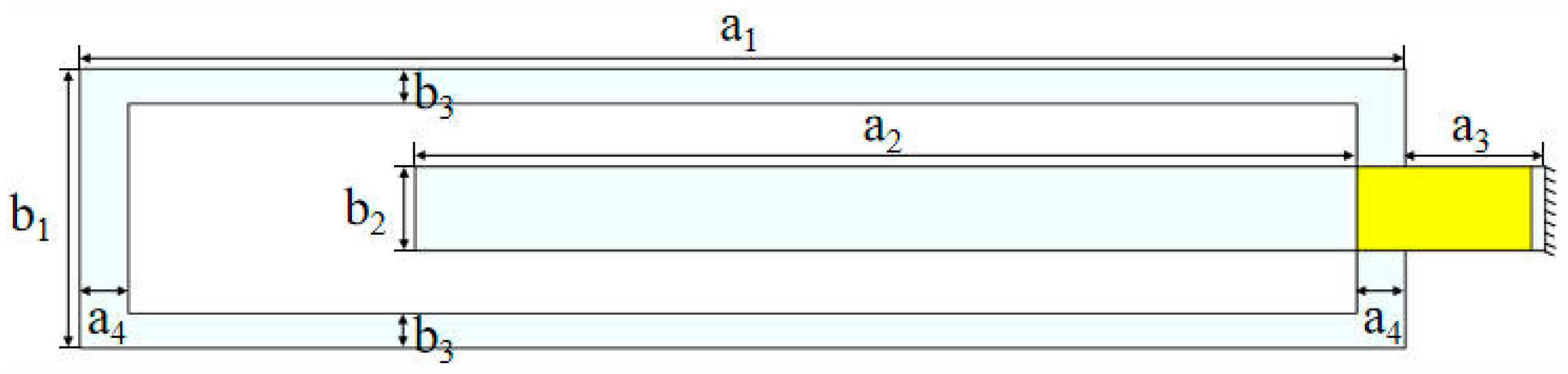
| Length a1/mm | 190 |
| Length a2/mm | 135 |
| Length a3/mm | 20 |
| Length a4/mm | 7 |
| Width b1/mm | 40 |
| Width b2/mm | 12 |
| Width b3/mm | 5 |
| Thickness/mm | 1 |
| PZT-5H | |
| Density/(kg·m−3) | 7500 |
| Length/mm | 25 |
| Width/mm | 12 |
| Thickness/mm | 0.2 |
| Piezoelectric constant | 1704.4/1704.4/1 433.6 |
Disclaimer/Publisher’s Note: The statements, opinions and data contained in all publications are solely those of the individual author(s) and contributor(s) and not of MDPI and/or the editor(s). MDPI and/or the editor(s) disclaim responsibility for any injury to people or property resulting from any ideas, methods, instructions or products referred to in the content. |
© 2025 by the authors. Licensee MDPI, Basel, Switzerland. This article is an open access article distributed under the terms and conditions of the Creative Commons Attribution (CC BY) license (https://creativecommons.org/licenses/by/4.0/).
Share and Cite
Fan, X.; Zhao, C.; Jiang, W. Experiment of a Cut-Out Piezoelectric Beam Energy Harvester Under Wind-Induced Vibration. Micromachines 2025, 16, 378. https://doi.org/10.3390/mi16040378
Fan X, Zhao C, Jiang W. Experiment of a Cut-Out Piezoelectric Beam Energy Harvester Under Wind-Induced Vibration. Micromachines. 2025; 16(4):378. https://doi.org/10.3390/mi16040378
Chicago/Turabian StyleFan, Xuhong, Chongming Zhao, and Wenan Jiang. 2025. "Experiment of a Cut-Out Piezoelectric Beam Energy Harvester Under Wind-Induced Vibration" Micromachines 16, no. 4: 378. https://doi.org/10.3390/mi16040378
APA StyleFan, X., Zhao, C., & Jiang, W. (2025). Experiment of a Cut-Out Piezoelectric Beam Energy Harvester Under Wind-Induced Vibration. Micromachines, 16(4), 378. https://doi.org/10.3390/mi16040378