
Characterization of the Coating Layers Deposited onto Curved Surfaces Using a Novel Multi-Nozzle Extrusion Printer


Abstract
1. Introduction
2. Materials and Methods
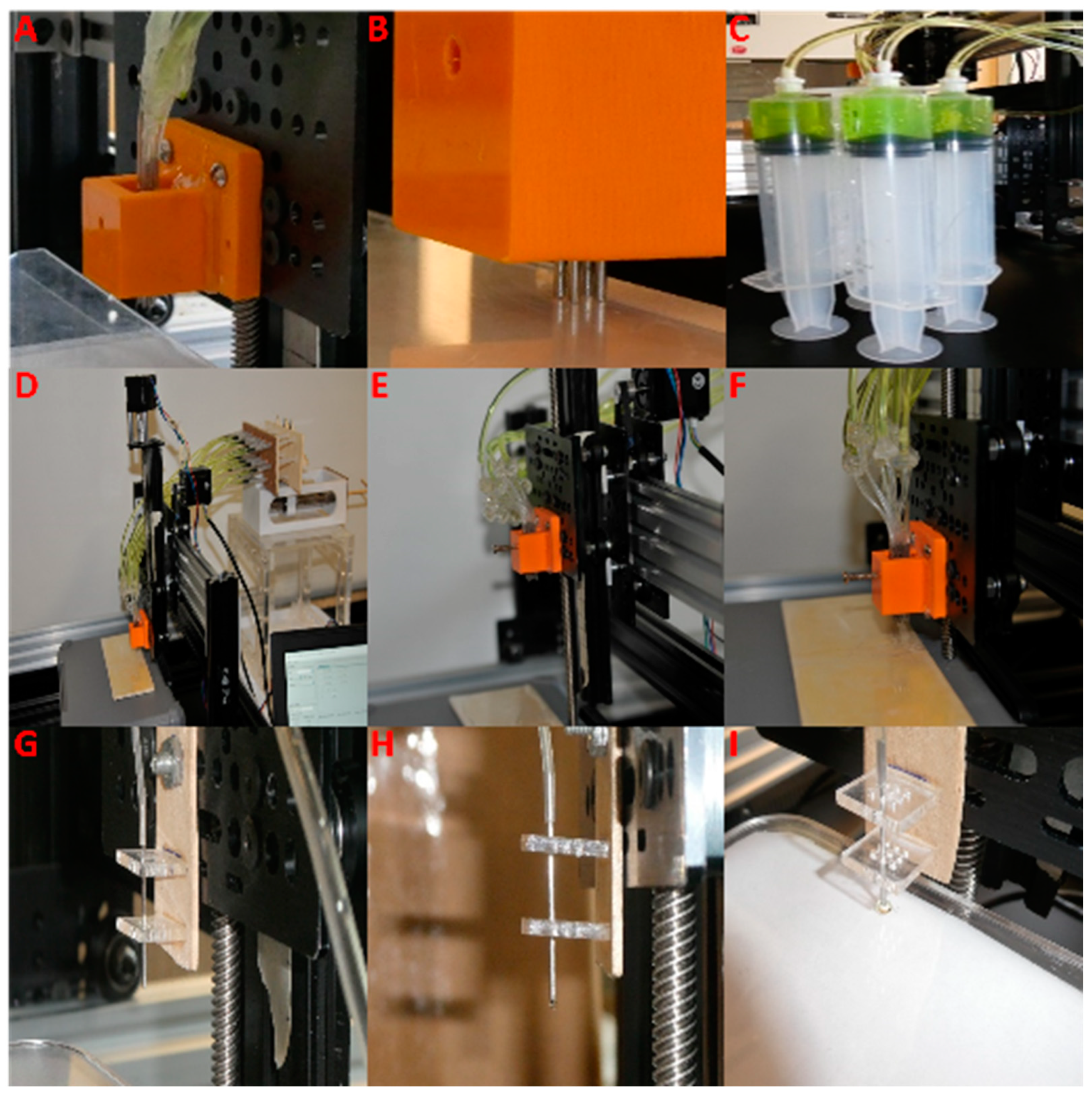
2.1. Multi-Nozzle Extrusion 3D Printer
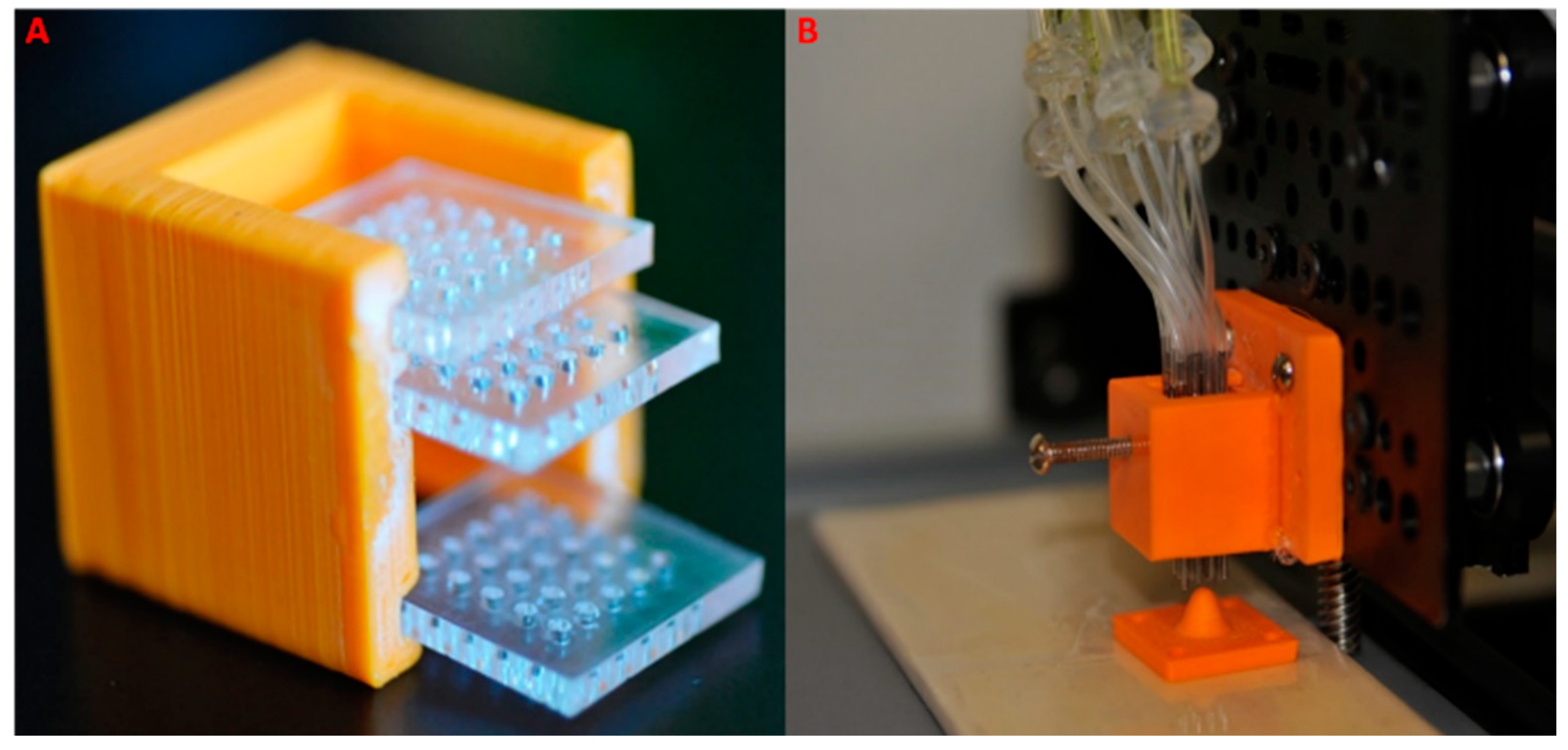
2.1.1. Multi-Nozzle Attachment
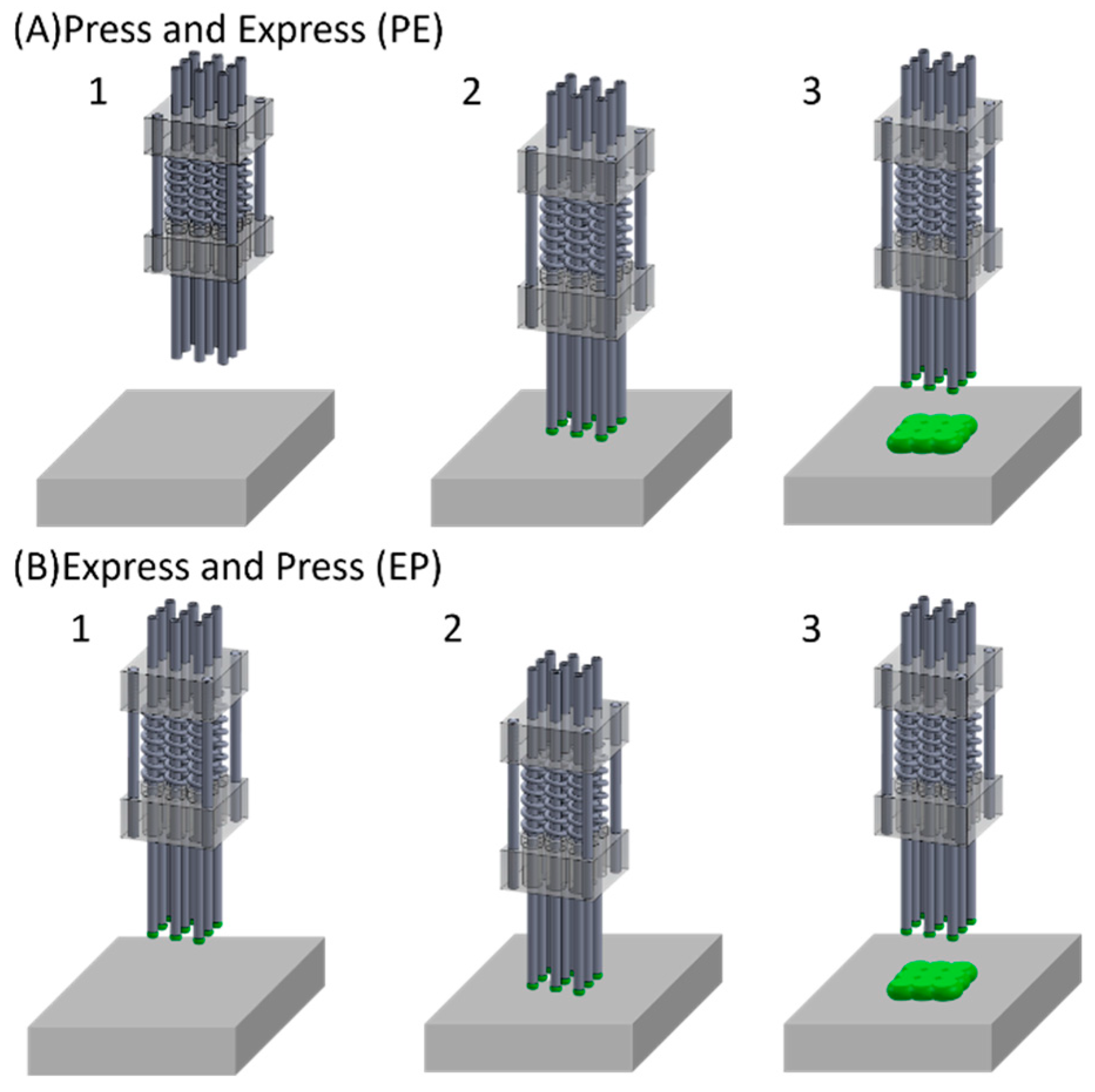
2.1.2. Printing Process
2.2. Mathematical Modeling
- The gel behaves as an incompressible fluid, with no retraction into the nozzles once expressed.
- The droplets’ geometry, resembling a truncated sphere with a diameter 1.5 times greater than the corresponding nozzle’s diameter (dD), is deemed stable, validated by experimental observations (as depicted in Supplementary Figure S1).
- Homogeneous merging characterizes all deposited droplets.
3. Results and Discussions
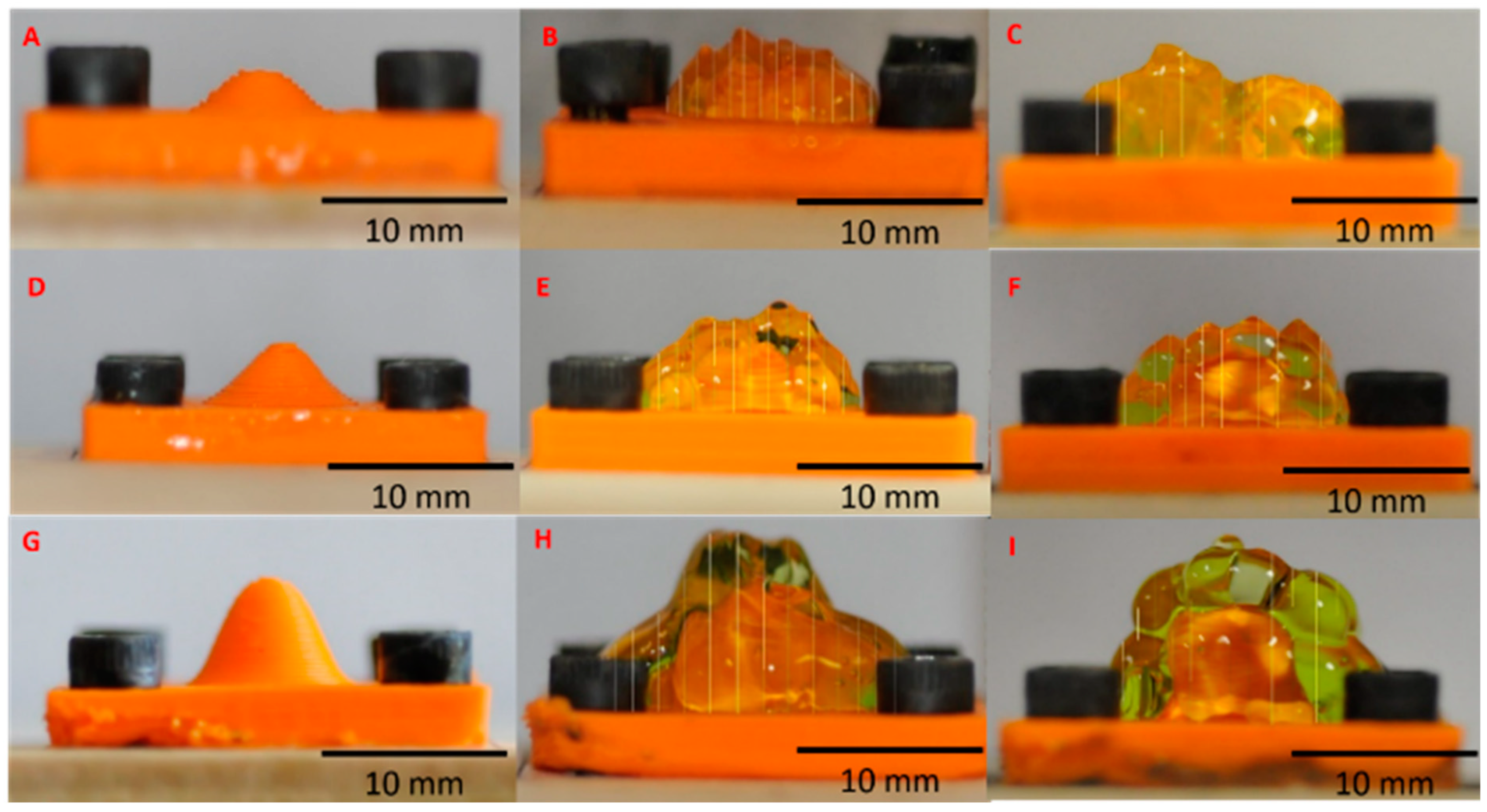
3.1. Characterization of Single-Droplet Deposition on a Flat Surface
3.2. Gel Deposition over a Flat Surface Using a 4-Nozzle Array
3.3. The Deposition of Gel onto a Flat Surface Employing a 16-Nozzle Array
3.4. The Deposition of Gel on a Curved Surface Employing a 16-Nozzle Array
3.5. Selective Displacement Imprinting Technique
4. Conclusions
Supplementary Materials
Author Contributions
Funding
Data Availability Statement
Conflicts of Interest
References
- Ventola, C.L. Medical applications for 3d printing: Current and projected uses. P&T 2014, 39, 704–711. [Google Scholar]
- Natu, R.; Herbertson, L.; Sena, G.; Strachan, K.; Guha, S. A systematic analysis of recent technology trends of microfluidic medical devices in the united states. Micromachines 2023, 14, 1293. [Google Scholar] [CrossRef]
- Ghilan, A.; Chiriac, A.P.; Nita, L.E.; Rusu, A.G.; Neamtu, L.; Chiriac, V.M. Trends in 3d printing processes for biomedical field: Opportunities and challenges. J. Environ. Polym. Degrad. 2020, 28, 1345–1367. [Google Scholar]
- Wang, D.D.; Qian, Z.; Vukicevic, M.; Engelhardt, S.; Kheradvar, A.; Zhang, C.; Little, S.H.; Verjans, J.; Comaniciu, D.; O’Neill, W.W.; et al. 3d printing, computational modeling, and artificial intelligence for structural heart disease. JACC Cardiovasc. Imaging 2021, 14, 41–60. [Google Scholar] [CrossRef]
- Gardan, J. Additive manufacturing technologies: State of the art and trends. Int. J. Prod. Res. 2016, 54, 3118–3132. [Google Scholar] [CrossRef]
- Ngo, T.D.; Kashani, A.; Imbalzano, G.; Nguyen, K.T.Q.; Hui, D. Additive manufacturing (3d printing): A review of materials, methods, applications and challenges. Compos. B 2018, 143, 172–196. [Google Scholar]
- Chacon, J.M.; Caminero, M.A.; Garcia-Plaza, E.; Nuñez, P.J. Additive manufacturing of pla structures using fused deposition modelling: Effect of process parameteres on mechanical properties and their optimal selection. Mater. Des. 2017, 124, 143–157. [Google Scholar] [CrossRef]
- Schiele, N.R.; Koppes, R.A.; Corr, D.T.; Ellison, K.S.; Thompson, D.M.; Ligon, L.A.; Lippert, T.K.M.; Chrisey, D.B. Laser direct writing of combinatorial libraries of idealized cellular constructs: Biomedical applications. Appl. Surf. Sci. 2009, 255, 5444–5447. [Google Scholar] [CrossRef]
- Williams, J.M.; Adewunmi, A.; Schek, R.M.; Flanagan, C.L.; Krebsbach, P.H.; Feinberg, S.E.; Hollister, S.J.; Das, S. Bone tissure engineering using polycaprolactone scaffolds fabricated via selective laser sintering. Biomaterials 2005, 26, 4817–4827. [Google Scholar] [CrossRef]
- Nielsen, A.V.; Beauchamp, M.J.; Nordin, G.P.; Woolley, A.T. 3d printed microfluidics. Annu. Rev. Anal. Chem. 2020, 13, 45–65. [Google Scholar] [CrossRef]
- Anshori, I.; Lukito, V.; Adhawiyah, R.; Putri, D.; Harimurti, S.; Rajab, T.L.E.; Pradana, A.; Akbar, M.; Syamsunarno, M.R.A.A.; Handayani, M.; et al. Versatile and low-cost fabrication of modular lock-and-key microfluidics for integrated connector mixer using a stereolithography 3d printing. Micromachines 2022, 13, 1197. [Google Scholar] [CrossRef] [PubMed]
- Cheung, D.Y.; Duan, B.; Butcher, J.T. Current progress in tissue engineering of heart valves: Multiscale problems, multiscale solutions. Expert Opin. Biol. Ther. 2015, 15, 115–1172. [Google Scholar] [CrossRef] [PubMed]
- Hockaday, L.A.; Duan, B.; Kang, K.H.; Butcher, J.T. 3d-printed hydrogel technologies for tissue-engineered heart valves. 3D Print. Addit. Manuf. 2014, 1, 122–136. [Google Scholar] [CrossRef]
- Kheradvar, A.; Groves, E.M.; Dasi, L.P.; Alavi, S.H.; Tranquillo, R.; Grande-Allen, K.J.; Simmons, C.A.; Griffith, B.; Falahatpisheh, A.; Goergen, C.J.; et al. Emerging trends in heart valve engineering: Part i. Solutions for future. Ann. Biomed. Eng. 2015, 43, 833–843. [Google Scholar] [CrossRef]
- Alavi, S.H.; Kheradvar, A. A hybrid tissue-engineered heart valve. Ann. Thorac. Surg. 2015, 99, 2183–2187. [Google Scholar] [CrossRef]
- Zareian, R.; Zuke, S.D.; Morisawa, D.; Geertsema, R.S.; Majid, M.; Wynne, C.; Milliken, J.C.; Kheradvar, A. Early feasibility study of a hybrid tissue-engineered mitral valve in an ovine model. J. Cardiovasc. Dev. Dis. 2024, 11, 69. [Google Scholar] [CrossRef]
- Reuveny, S.; Velez, D.; Macmillan, J.D.; Miller, L. Factors affecting cell growth and monoclonal antibody production in stirred reactors. J Immunol. Methods 1986, 86, 53–59. [Google Scholar] [CrossRef]
- Placone, J.K.; Engler, A.J. Recent advances in extrusion-based 3d printing for biomedical applications. Adv. Healthc. Mater. 2018, 7, 1701161. [Google Scholar] [CrossRef]
- Freeman, S.; Ramos, R.; Chando, P.A.; Zhou, L.; Reeser, K.; Jin, S.; Soman, P.; Ye, K. A bioink blend for rotary 3d bioprinting tissue engineered small-diameter vascular constructs. Acta Biomater. 2019, 95, 152–164. [Google Scholar] [CrossRef]
- Liu, W.; Zhong, Z.; Hu, N.; Zhou, Y.; Maggio, L.; Miri, A.K.; Fragasso, A.; Jin, X.; Khademhosseini, A.; Zhang, Y.S. Coaxial extrusion bioprinting of 3d microfibrous constructs with cell-favorable gelatin methacryloyl microenvironments. Biofabrication 2018, 10, 024102. [Google Scholar] [CrossRef]
- Panwar, A.; Tan, L.P. Current status of bioinks for micro-extrusion-based 3d bioprinting. Molecules 2016, 21, 685. [Google Scholar] [CrossRef] [PubMed]
- Li, W.; Liu, Z.; Tang, F.; Jiang, H.; Zhou, Z.; Hao, X.; Zhang, J.M. Application of 3d bioprinting in liver diseases. Micromachines 2023, 14, 1648. [Google Scholar] [CrossRef]
- Khan, B.; Abdullah, S.; Khan, S. Current progress in conductive hydrogels and their applications in wearable bioelectronics and therapeutics. Micromachines 2023, 14, 1005. [Google Scholar] [CrossRef] [PubMed]
- Fan, Z.; Wei, X.; Chen, K.; Wang, L.; Xu, M. 3d bioprinting of an endothelialized liver lobule-like construct as a tumor-scale drug screening platform. Micromachines 2023, 14, 878. [Google Scholar] [CrossRef] [PubMed]
- Zhou, T.; NajafiKhoshnoo, S.; Esfandyarpour, R.; Kulinsky, L. Dissolvable calcium alginate microfibers produced via immersed microfluidic spinning. Micromachines 2023, 14, 318. [Google Scholar] [CrossRef]
- Fortunato, G.M.; Rossi, G.; Bonatti, A.F.; De Acutis, A.; Mendoza-Buenrostro, C.; Vozzi, G.; De Maria, C. Robotic platform and path planning algorithm for in situ bioprinting. Bioprinting 2021, 22, e00139. [Google Scholar] [CrossRef]
- Pelzer, L.; Hopmann, C. Additive manufacturing of non-planar layers with variable layer height. Addit. Manuf. 2021, 37, 101697. [Google Scholar] [CrossRef]
- Fortunato, G.M.; Nicoletta, M.; Batoni, E.; Vozzi, G.; De Maria, C. A fully automatic non-planar slicing algorithm for the additive manufacturing of complex geometries. Addit. Manuf. 2023, 69, 103541. [Google Scholar] [CrossRef]
- Uzel, S.G.M.; Weeks, R.D.; Eriksson, M.; Kokkinis, D.; Lewis, J.A. Multimaterial multinozzle adaptive 3d printing of soft materials. Adv. Mater. Technol. 2022, 7, 2101710. [Google Scholar] [CrossRef]

| Sample | Volume Deposition (µL) | Area (mm2) | Longitudinal Diameter (mm) | Transverse Diameter (mm) | Average Diameter (mm) |
|---|---|---|---|---|---|
| SF4A | 100 | 141.61 | 12.48 | 13.64 | 13.06 |
| SF4B | 200 | 339.66 | 20.97 | 18.77 | 19.87 |
| SF4C | 300 | 527.60 | 28.03 | 25.70 | 26.86 |
| Sample | Average Height (mm) | Minimum Height (mm) | Maximum Height (mm) | ||
| SF4D | 3.11 | 2.03 | 3.40 | ||
| SF4E | 3.85 | 2.09 | 5.14 | ||
| SF4F | 7.12 | 5.08 | 9.26 | ||
| Sample | Average Diameter (mm) | Average Height (mm) | Calculated Volume (µL) | Displaced Volume (µL) | Lost Gel Volume (µL) | Deposited Volume (µL) |
|---|---|---|---|---|---|---|
| SF3A | 13.06 | 3.11 | 416.22 | 1600 | 1183.78 | 416.22 |
| SF3B | 19.87 | 3.85 | 1192.64 | 3200 | 2007.36 | 1192.64 |
| SF3C | 26.86 | 7.12 | 4034.43 | 4800 | 765.57 | 4034.43 |
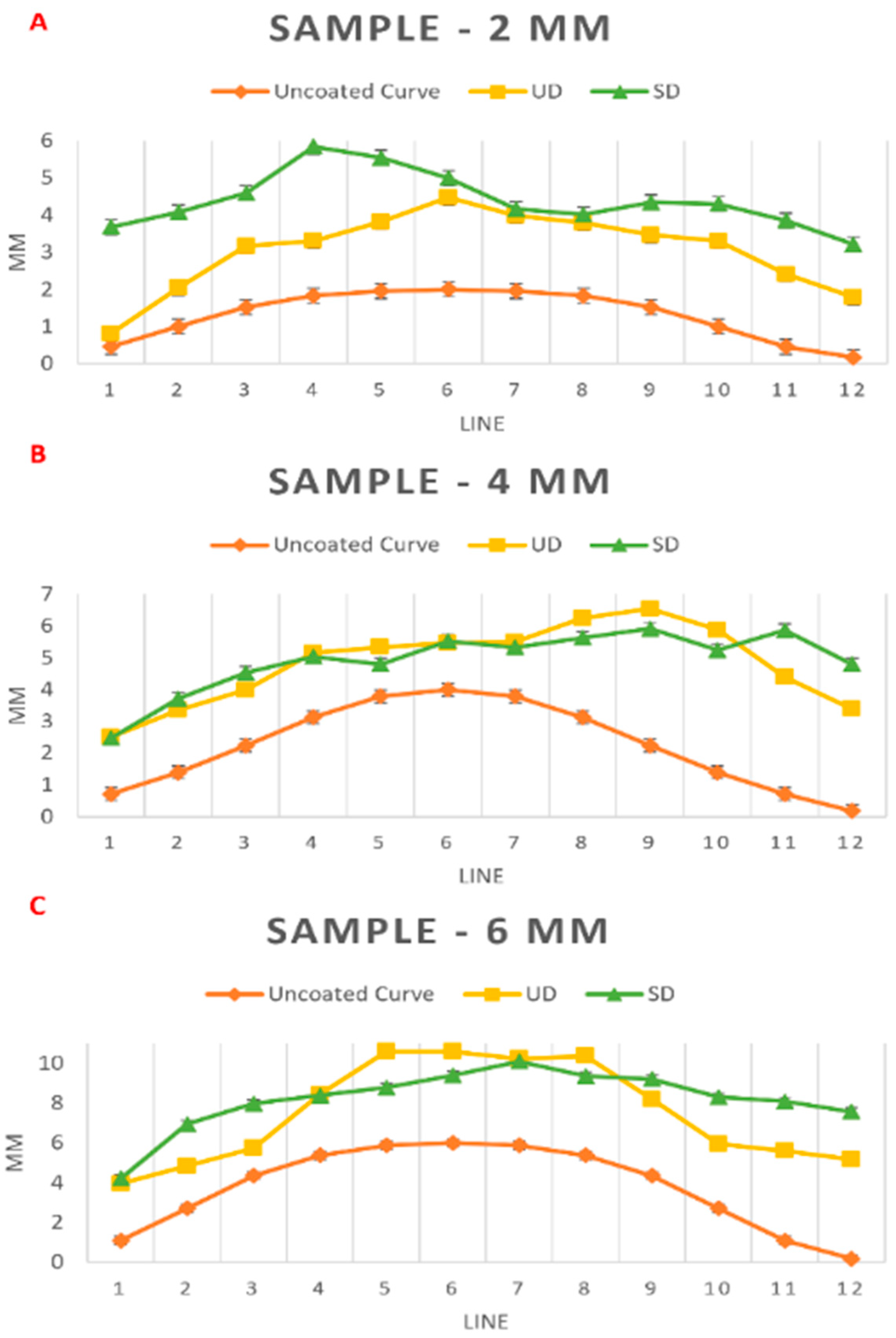
| Sample: 2 mm | ||||||||||||
| Line | 1 | 2 | 3 | 4 | 5 | 6 | 7 | 8 | 9 | 10 | 11 | 12 |
| Uncoated Curve (mm) | 0.46 | 1 | 1.52 | 1.83 | 1.96 | 2 | 1.96 | 1.83 | 1.52 | 1 | 0.46 | 0.17 |
| UD (mm) | 0.81 | 2.05 | 3.17 | 3.31 | 3.82 | 4.47 | 3.98 | 3.79 | 3.46 | 3.3 | 2.41 | 1.79 |
| SD (mm) | 3.68 | 4.08 | 4.59 | 5.84 | 5.54 | 5 | 4.16 | 4.01 | 4.34 | 4.3 | 3.86 | 3.21 |
| Sample: 4 mm | ||||||||||||
| Line | 1 | 2 | 3 | 4 | 5 | 6 | 7 | 8 | 9 | 10 | 11 | 12 |
| Uncoated Curve (mm) | 0.71 | 1.39 | 2.24 | 3.13 | 3.79 | 4 | 3.79 | 3.13 | 2.24 | 1.39 | 0.71 | 0.18 |
| UD (mm) | 2.51 | 3.36 | 3.99 | 5.15 | 5.34 | 5.47 | 5.5 | 6.25 | 6.54 | 5.88 | 4.4 | 3.39 |
| SD (mm) | 2.47 | 3.71 | 4.53 | 5.04 | 4.8 | 5.53 | 5.34 | 5.63 | 5.92 | 5.24 | 5.87 | 4.8 |
| Sample: 6 mm | ||||||||||||
| Line | 1 | 2 | 3 | 4 | 5 | 6 | 7 | 8 | 9 | 10 | 11 | 12 |
| Uncoated Curve (mm) | 1.09 | 2.71 | 4.35 | 5.37 | 5.87 | 6 | 5.87 | 5.37 | 4.35 | 2.71 | 1.09 | 0.17 |
| UD (mm) | 3.95 | 4.83 | 5.74 | 8.44 | 10.6 | 10.6 | 10.23 | 10.37 | 8.2 | 5.94 | 5.6 | 5.16 |
| SD (mm) | 4.21 | 6.94 | 7.97 | 8.39 | 8.78 | 9.39 | 10.09 | 9.36 | 9.21 | 8.3 | 8.09 | 7.57 |
Disclaimer/Publisher’s Note: The statements, opinions and data contained in all publications are solely those of the individual author(s) and contributor(s) and not of MDPI and/or the editor(s). MDPI and/or the editor(s) disclaim responsibility for any injury to people or property resulting from any ideas, methods, instructions or products referred to in the content. |
© 2025 by the authors. Licensee MDPI, Basel, Switzerland. This article is an open access article distributed under the terms and conditions of the Creative Commons Attribution (CC BY) license (https://creativecommons.org/licenses/by/4.0/).
Share and Cite
Trigo Torres, R.S.; Kulinsky, L.; Kheradvar, A. Characterization of the Coating Layers Deposited onto Curved Surfaces Using a Novel Multi-Nozzle Extrusion Printer. Micromachines 2025, 16, 505. https://doi.org/10.3390/mi16050505
Trigo Torres RS, Kulinsky L, Kheradvar A. Characterization of the Coating Layers Deposited onto Curved Surfaces Using a Novel Multi-Nozzle Extrusion Printer. Micromachines. 2025; 16(5):505. https://doi.org/10.3390/mi16050505
Chicago/Turabian StyleTrigo Torres, Ramses Seferino, Lawrence Kulinsky, and Arash Kheradvar. 2025. "Characterization of the Coating Layers Deposited onto Curved Surfaces Using a Novel Multi-Nozzle Extrusion Printer" Micromachines 16, no. 5: 505. https://doi.org/10.3390/mi16050505
APA StyleTrigo Torres, R. S., Kulinsky, L., & Kheradvar, A. (2025). Characterization of the Coating Layers Deposited onto Curved Surfaces Using a Novel Multi-Nozzle Extrusion Printer. Micromachines, 16(5), 505. https://doi.org/10.3390/mi16050505