Article

An Electromagnetic MEMS Energy Harvester Array with Multiple Vibration Modes

1
Jiangsu Provincial Key Labratory of Advanced Robotics, and Collaborative Innovation Center of Suzhou Nano Science and Technology, Soochow University, Suzhou 215123, China
2
Department of Electrical & Computer Engineering, National University of Singapore, 4 Engineering Drive 3, Singapore 117576, Singapore
*
Author to whom correspondence should be addressed.
Micromachines 2015, 6(8), 984-992; https://doi.org/10.3390/mi6080984
Submission received: 10 May 2015 / Revised: 2 July 2015 / Accepted: 10 July 2015 / Published: 24 July 2015

Abstract

:
This paper reports the design, micromachining and characterization of an array of electromagnetic energy harvesters (EHs) with multiple frequency peaks. The authors present the combination of three multi-modal spring-mass structures so as to realize at least nine resonant peaks within a single microelectromechanical systems (MEMS) chip. It is assembled with permanent magnet to show an electromagnetic-based energy harvesting capability. This is the first demonstration of multi-frequency MEMS EH existing with more than three resonant peaks within a limited frequency range of 189 to 662 Hz. It provides a more effective approach to harvest energy from the vibration sources of multiple frequency peaks.

1. Introduction

For wireless sensing nodes and electronic devices, one of the main concerns is the lifetime of the battery-powered system. With the fast development of microelectromechanical systems (MEMS) and low-power wireless sensor networks, vibration-based energy harvesters (EHs) are increasingly important as an alternative to batteries for long lasting time and environmental protection [1,2]. Previously, tremendous EHs based on piezoelectric, electromagnetic and electrostatic transduction principles have been demonstrated with single dominant resonant frequency [3,4,5,6,7,8,9,10]. However, the practical vibration sources may exhibit multiple frequency peaks over a wide bandwidth [11]. The key issue is that the resonant frequency of the EH device mismatches ambient vibration frequencies. It is necessary to develop multi-frequency or wideband EHs to collect efficient energy from different vibration peaks [12,13,14].
The present multi-frequency approaches can be categorized into two major groups. A straightforward approach reported by Sari et al. [15] is to employ arrays of 35 oscillating cantilevers, and each has different resonant frequency. The electrical current will be generated by means of the relative movement between the coil coated on the cantilever and a fixed magnet. By adjusting the length increments so that they are sufficiently small, the EH device shows an overlapping multi-frequency spectrum from 4.2 to 5 kHz. Ferrari et al. [16] has reported a similar multi-frequency strategy by using three piezoelectric bimorphs. The resonant frequencies of the bimorphs are 113, 183 and 281 Hz, respectively. The results show the possibility of an overall broadened bandwidth of the EH array. The second approach is concentrated on multiple vibration modes, while each mode represents one resonant frequency. Ching et al. [17] and Liu et al. [18,19] have respectively employed spiral and circular spring structures connected with center mass to realize electromagnetic energy harvesting with three distinct vibration modes. Yang et al. [20] have attached multiple individual masses along a fixed-fixed beam for achieving multiple vibration modes of the device. Among these works, the multi-frequency MEMS devices were limited to be around three resonant peaks. Chew and Li [21] utilized nine off-the-shelf piezoelectric cantilevers and linked end-to-end to form a 3D spring structure. The experimental results showed at least seven resonant peaks from frequency range of 100 to 1000 Hz. However, the major problem is its large volume and the in-compatibility of MEMS technique.
In this paper, a subtle integration of harvesting array mechanism with multiple vibration modes is successfully implemented in a single MEMS chip. The chip is micromachined and assembled with permanent magnets to achieve electromagnetic induced energy harvesting capability. The EH device consisting of three distinct harvesters exhibits as many as nine resonant peaks. The design, micromachining and characterization of the EH device will be introduced and discussed subsequently in the following sections.

2. Design and Fabrication

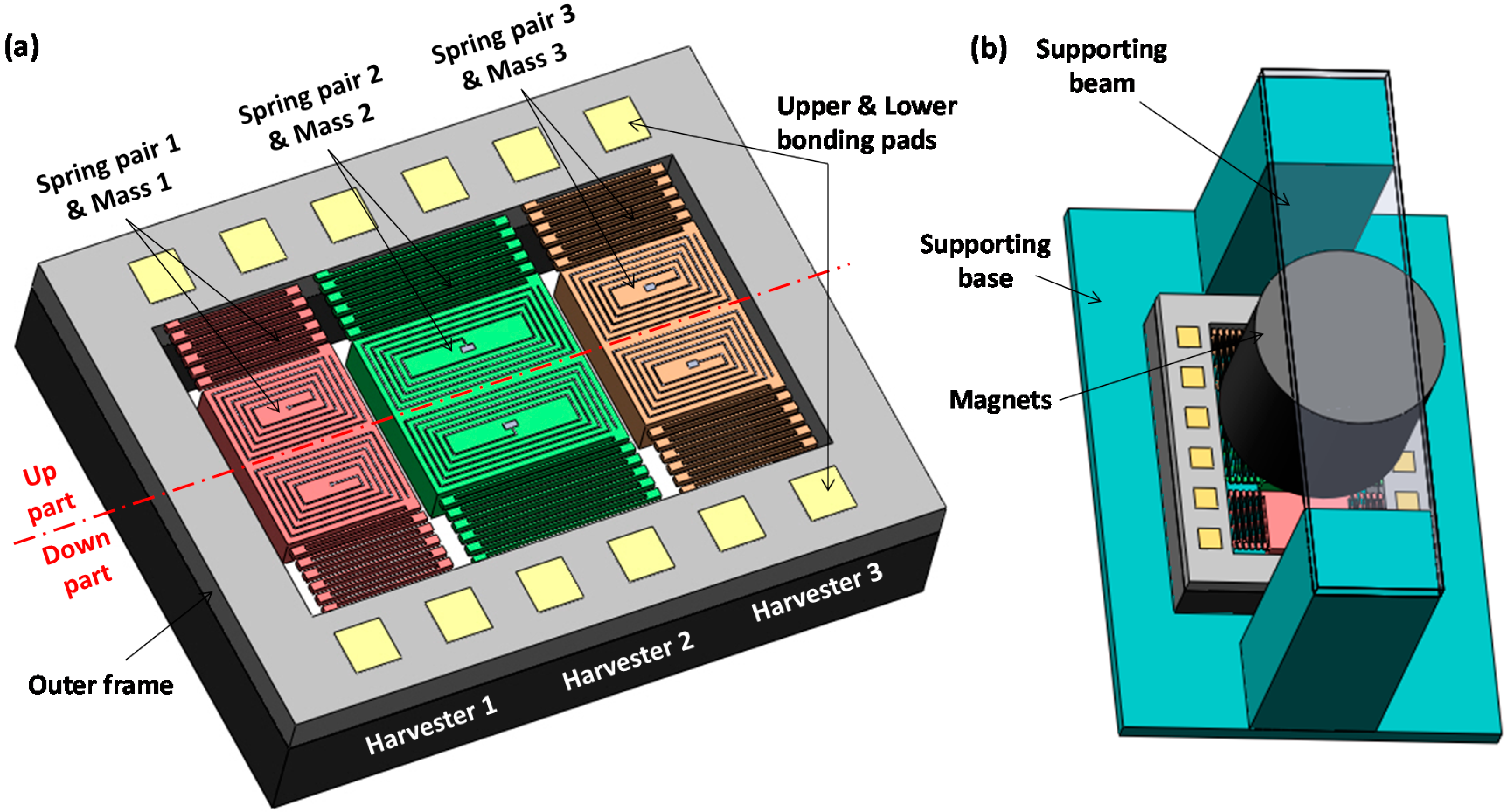
2.1. Device Configuration

Figure 1a shows a 3D drawing of the proposed electromagnetic MEMS EH array. It consists of three distinct spring-mass structures, named as harvesters 1, 2, and 3. Each harvester contains a proof mass suspended by two folded springs located respectively at the up and down parts of the chip. The proof masses are patterned with spiral-shaped aluminum (Al) coils which are symmetrical about the center line. The double-layer Al coil of 10 μm in width and 1 μm in depth are isolated by Si3N4 layer on the Si chip. The up coil is connected to the corresponding up bonding pads through the up folded springs, while the down coil is similarly connected to their down bonding pads. Each folded spring contains 11 beams with the beam width of 30 μm, spacing of 70 μm, and thickness of 150 μm, while the width and thickness of each proof mass are 2.66 mm and 400 μm, respectively. The beam and mass lengths of the harvesters 1, 2 and 3 are 2.0, 2.9 and 2.1 mm, respectively, resulting in different resonance ranges of these three harvesters. The overall MEMS EH chip size is 10 mm in length, 8 mm in width and 0.4 mm in thickness. In Figure 1b, the MEMS EH chip is bonded on a supporting base. Two cylindrical permanent magnets with diameter of 3 mm and height of 2 mm are placed on top of the harvester array via a supporting beam. When the three harvesters oscillate in different vibration modes, ambient vibration energy will be converted into electrical energy according to Faraday’s law of induction.
Figure 1. 3D drawing of (a) the proposed multi-frequency microelectromechanical systems (MEMS) energy harvester (EH) chip and (b) the assembled electromagnetic EH device.
Micromachines 06 00984 g001

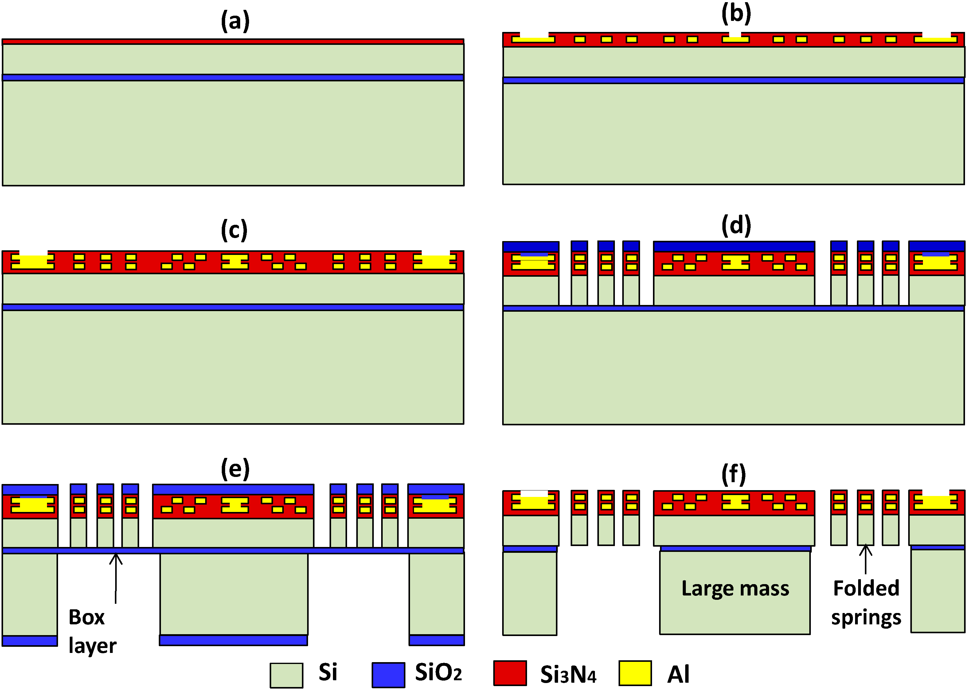
2.2. Micromachining Process

Figure 2 shows the complementary metal oxide semiconductor (CMOS)-compatible micromachining process of the EH array. It starts from a silicon on insulator (SOI) wafer with a 150-μm-thick Si device layer, a 1-μm-thick buried oxide (BOX) layer and a 725-μm-thick Si handling layer. Firstly, the frontside surface of the SOI wafer is deposited with a 0.1-μm-thick Si3N4 insulation layer by plasma-enhanced chemical vapor deposition (PECVD) at 400 °C (Figure 2a). In Figure 2b, the bottom metal coils, bonding pads and metal via of 1-μm-thick Al are formed by physical vapor deposition (PVD) at 100 °C, patterning, and reactive ion etching (RIE) in succession. It should be noted that the Al coil has a relatively low melting temperature, i.e., 660 °C, hence the follow-up processing temperature must be lower than 660 °C. Next, a 0.8-μm-thick Si3N4 layer, which serves as the electrical insulation, is deposited by PECVD. In Figure 2c, the top metal coils and bonding pads of 1-μm-thick Al are constructed by the similar processes as Figure 2b. Subsequently, a 0.8-μm-thick Si3N4 insulation layer is deposited by PECVD and pad openings are formed by RIE process. In Figure 2d, a 2-μm-thick SiO2 layer is deposited by PECVD at 400 °C as a hard mask layer. Then the frontside features of spring pairs and masses are patterned by the RIE of the SiO2, Si3N4 layers and the deep RIE of the 150-μm-thick Si device layer. Later on, the thickness of the SOI wafer is reduced to be around 400 μm by the backside grinding and polishing. In Figure 2e, a 2-μm-thick SiO2 layer is deposited on the backside surface as the hard mask and the deep RIE steps are followed to pattern the Si handling layer. Finally, the remaining SiO2 layers are dry etched by CHF3 plasma as shown in Figure 2f, such that the spring-mass structures are completely released.
Figure 2. Microfabrication process of the EH array device. (a) Si3N4 deposition; (b) patterning of the 1st metal and isolation layers; (c) patterning of the 2nd metal and isolation layers; (d) frontside deep reactive ion etching (DRIE); (e) grounding and backside DRIE; (f) etch of SiO2.
Micromachines 06 00984 g002

2.3. Mode Analysis

The mode analysis is conducted by finite element analysis software Abaqus. The first three vibration modes of each single harvester are found to be in-plane along x-axis at mode I, in-plane along y-axis at mode II and out-of-plane along z-axis at mode III. The EH array contains three harvesters with distinct dimensions of springs and masses. The larger spring length and mass of harvester 2 result in low resonant modes of 158 (at mode I), 346 (at mode II) and 377 (at mode III) Hz, respectively. By contrast, smaller spring-mass structures lead to relatively higher resonant modes, which are 368 (at mode I), 530 (at mode II) and 614 (at mode III) Hz respectively for harvester 1, and 295 (at mode I), 475 (at mode II) and 543 Hz (at mode III) respectively for harvester 3. Therefore, the overall vibration modes of the device are the combination of nine different resonances ranging from 158 to 614 Hz as listed in Table 1.
Table 1. Simulated vibration modes summary of the energy harvester (EH) array device.
EH Array Micromachines 06 00984 i001 Micromachines 06 00984 i002 Micromachines 06 00984 i003
Harvester 1368 Hz530 Hz614 Hz
Harvester 2158 Hz346 Hz377 Hz
Harvester 3295 Hz475 Hz543 Hz

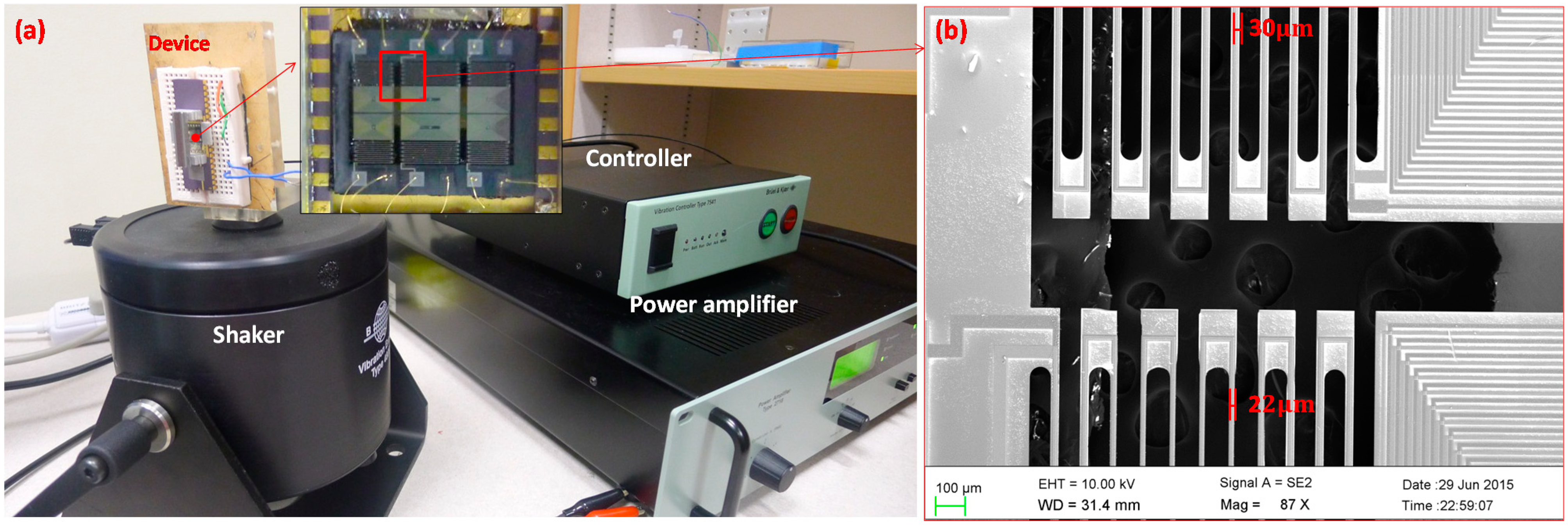
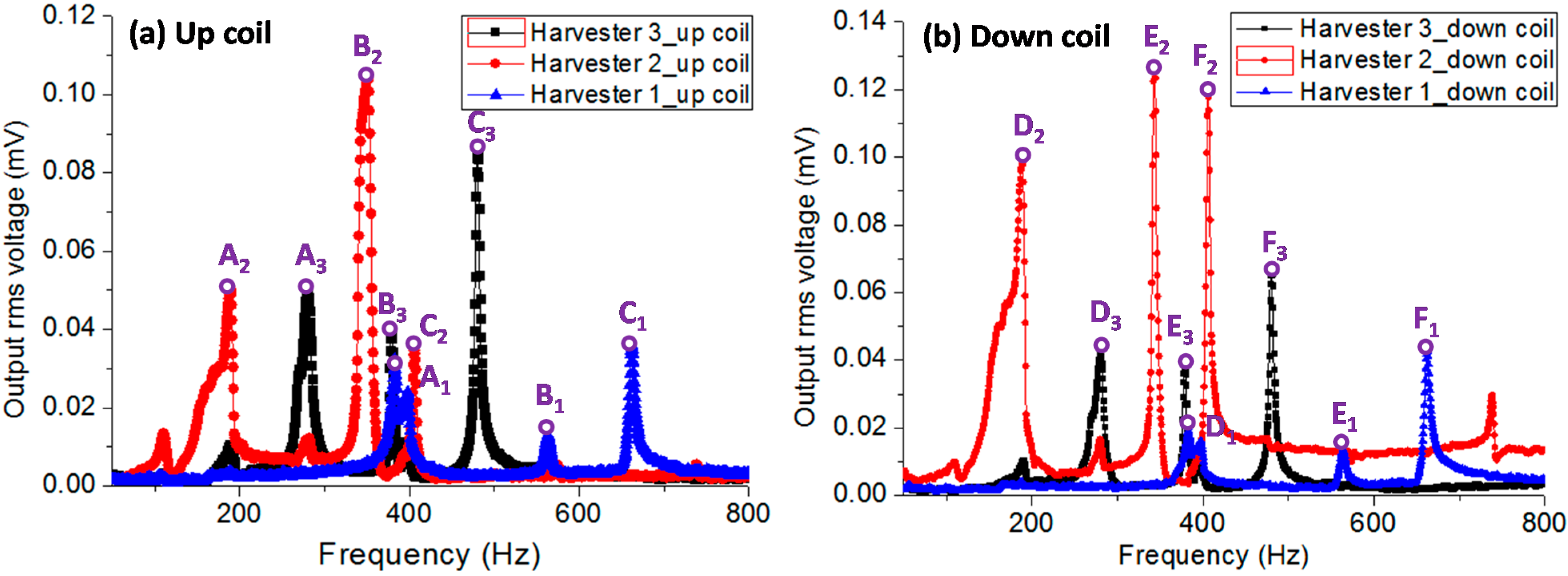
3. Experiments and Discussion

The experiments are conducted by using a vibration control system as shown in Figure 3. It contains an electromagnetic shaker and a power amplifier, which produce vibrations at different frequencies and accelerations. The shaker is driven by using control software which sends a signal through a controller. The EH array device is assembled on an L-shaped plate and then fixed to the shaker, such that the vertical excitation of the shaker is along the x-axis of the MEMS chip. An accelerometer attached on the L-shaped plate is used to measure the acceleration level and sent the feedback signal to the controller. In the test, frequency sweeps are conducted from 50 to 800 Hz at a constant acceleration and the output voltages of the device are collected via a vibration control channel which is then transferred to the computer software using an ethernet port.
The open-circuit rms voltages of the EH array against frequencies for up and down coils are characterized at acceleration of 1 g along x-axis. It is obvious from Figure 4 that the overall voltage spectrum of the EH array shows nine resonant peaks ranging from 189 to 662 Hz. Due to the larger spring length and mass, harvester 2 produces relatively larger output voltages of 0.050, 0.105 and 0.035 mV for up coil at points A2, B2 and C2, and 0.099, 0.127 and 0.120 mV for down coil at points D2, E2 and F2, at the lower resonant frequencies of 189, 348 and 406 Hz, respectively. For harvester 3, the three resonant modes are 280, 379 and 479 Hz. The corresponding voltages are 0.05, 0.039 and 0.085 mV for up coil (points A3, B3 and C3) and 0.042, 0.037 and 0.066 mV for down coil (points D3, E3 and F3). For harvester 1, since the spring length is shorter and the mass is smaller, the three resonant modes of 382, 563 and 662 Hz are higher but the output voltages are relatively lower, which are 0.032, 0.013 and 0.036 mV for up coil (points A1, B1 and C1) and 0.02, 0.014 and 0.043 mV for down coil (points D1, E1 and F1). The enlarged scanning electron microscope (SEM) image is shown in Figure 3b. It is found that the spring beam is uneven etched which results in the frequency shift of the device comparing to the simulation results.
The open circuit voltage Vrms can be considered as the generated voltage of the harvester. Hence, the output power P is expressed as:
P = [ V r m s R L + R C ] 2 × R L
As long as the load resistance RL is matched with the internal resistance of the coil RC, the maximum output power Pmax is obtained as:
P max = V r m s 2 / 4 R C
The resistance of up and down coils for harvester 1, 2 and 3 are measured and the maximum output power and power density is calculated according to Equation (2). It is seen from Table 2 that the output voltage and power of current prototype is relatively low. Because the mass movement is relatively small for each harvester at different modes, the magnetic flux change across the limited coils is not significant. In addition, the winding coil is limited due to a very small mass area.
Figure 3. (a) A closed-loop vibration control system with assembled EH array device; (b) the scanning electron microscope (SEM) image of the enlarge spring.
Micromachines 06 00984 g003
Figure 4. The output voltages of the EH array against frequencies for (a) up and (b) down coils at acceleration of 1 g along x-axis.
Micromachines 06 00984 g004
Table 2. Output performance summary of the EH array device.
EH ArrayResonant Modes (Hz)Output rms Voltage (mV)Power (μW)Power Density (μW/cm3)
Up CoilDown Coil
Harvester 1Mode I3820.0320.0201.086 × 10−60.034 × 10⁻³
R1up = 362 ΩMode II5630.0130.0140.303 × 10−60.010 × 10⁻³
R1down = 264 ΩMode III6620.0360.0432.646 × 10−60.083 × 10⁻³
Harvester 2Mode I1890.0500.0997.433 × 10−60.232 × 10⁻³
R2up = 457 ΩMode II3480.1050.12716.012 × 10−60.500 × 10⁻³
R2down = 404 ΩMode III4060.0350.1209.581 × 10−60.299 × 10⁻³
Harvester 3Mode I2800.0500.0422.851 × 10−60.089 × 10⁻³
R3up = 428 ΩMode II3790.0390.0371.968 × 10−60.062 × 10⁻³
R3down = 317 ΩMode III4790.0850.0667.655 × 10−60.239 × 10⁻³
On the basis of current design concept of multi-mode harvesting array, future works will be conducted to further improve the output voltage and power, by optimizing the dimension of the spring-mass structures, the construction of the coil patterns and the distribution of the magnetic flux. Firstly, the chip size and harvester array arrangement will be re-defined. The spring-mass structure will be optimized from folded springs to spiral springs [17] as shown in Table 3. Finite element analysis shows that the spiral springs have lower spring constant and lower stress concentration; thus, a larger displacement can be obtained and better fatigue loading can be endured. By the same means, not only can the coil area be increased, but also can the spring deformation or the mass displacement. Meanwhile, the spring stiffness as well as the resonant frequency is easy to be reduced or adjusted. Secondly, the patterned coil width and spacing can be further reduced from 10 to 5 μm. The increased coil density would greatly enhance the voltage output. Thirdly, the magnet will be changed from a circular bulk to a square array with alternating south and north poles and strong magnetic flux. The magnet array will be designed to match with the moving mass. In addition, the gap distance between the magnet and coil will be further reduced. In case of design optimization, a rough estimation of the obtained power can be several hundred times higher than the current prototype. Anyway, this prototype shows a promising design concept for multi-frequency MEMS energy harvester. However, high power generation of the device is still a great challenge and requires further exploration.
Table 3. Stress analysis for folded and spiral spring structures.
Total Frame Area 12.5 mm2Stress Distribution for MassStress Distribution for Mass
Total Mass Area 5.3 mm2Displacement of z = 1 mmDisplacement of x = 0.5 mm
Micromachines 06 00984 i004 Micromachines 06 00984 i005 Micromachines 06 00984 i006
Micromachines 06 00984 i007 Micromachines 06 00984 i008 Micromachines 06 00984 i009

4. Conclusions

A design of a multiple resonant frequency microstructure array for electromagnetic energy harvesting applications has been proposed. The EH array has been microfabricated and fully characterized using a closed-loop vibration control system. It is found that every microharvester has three resonant modes. By combining the three microharvesters with different dimensions, the EH array has at least nine noticeable resonant peaks from 100 to 800 Hz. The open-circuit output voltages at the three resonances are varying from 0.01 to 0.13 mV. This is the first demonstration of multi-frequency MEMS EH with nine resonant peaks. With further optimization in the design and dimensional parameters, it is expected that the design would improve the effectiveness in harvesting the ambient kinetic energy from vibrations with multiple peaks.

Acknowledgments

This work is partially supported by the National Natural Science Foundation of China (Grant No. 51405318), the Foundation Research Project of Jiangsu Province (Grant No. BK 20140335) and the National High Technology Research and Development Program of China (863 Program) (Grant No. 2015AA043502). The authors would like to thank Jianxiang Wang in the College of Physics, Optoelectronics and Energy, Soochow University for the dynamic observation.

Author Contributions

Huicong Liu, Tao Chen, and Lining Sun conceived and designed the experiments; Huicong Liu and Chengkuo Lee fabricated and provided the energy harvesting device; Huicong Liu performed the experiments, analyzed the data and images and wrote the paper.

Conflicts of Interest

The authors declare no conflict of interest.

References

  1. Mitcheson, P.D.; Yeatman, E.M.; Rao, G.K.; Holmes, A.H.; Green, T.C. Energy Harvesting From Human and Machine Motion for Wireless Electronic Devices. Proc. IEEE 2008, 96, 1457–1486. [Google Scholar] [CrossRef] [Green Version]
  2. Matiko, J.W.; Grabham, N.J.; Beeby, S.P.; Tudor, M.J. Review of the application of energy harvesting in buildings. Meas. Sci. Technol. 2014, 25, 012002. [Google Scholar] [CrossRef]
  3. Aktakka, E.E.; Peterson, R.L.; Najafi, K. A CMOS-compatible piezoelectric vibration energy scavenger based on the integration of bulk PZT films on silicon. In Proceedings of 2010 IEEE International Electron Devices Meeting (IEDM), San Francisco, CA, USA, 6–8 December 2010.
  4. Elfrink, R.; Kamel, T.M.; Goedbloed, M.; Matova, S.; Hohlfeld, D.; van Andel, Y.; van Schaijk, R. Vibration energy harvesting with aluminum nitride-based piezoelectric devices. J. Micromech. Microeng. 2009, 19, 094005. [Google Scholar] [CrossRef]
  5. Tang, G.; Liu, J.Q.; Yang, B.; Luo, J.B.; Liu, H.S.; Li, Y.G.; Yang, C.S.; He, D.N.; Dao, V.D.; Tanaka, K. Fabrication and analysis of high-performance piezoelectric MEMS generators. J. Micromech. Microeng. 2012, 22, 065017. [Google Scholar] [CrossRef]
  6. Kulkarni, S.; Koukharenko, E.; Torah, R.; Tudor, J.; Beeby, S.; O’Donnell, T.; Roy, S. Design, fabrication and test of integrated micro-scale vibration-based electromagnetic generator. Sens. Actuators A Phys. 2008, 145, 336–342. [Google Scholar] [CrossRef]
  7. Liu, H.C.; Gudla, S.; Hassani, F.A.; Heng, C.H.; Lian, Y.; Lee, C.K. Investigation of the Nonlinear Electromagnetic Energy Harvesters From Hand Shaking. IEEE Sens. J. 2015, 15, 2356–2364. [Google Scholar] [CrossRef]
  8. Feng, Y.; Hagiwara, K.; Iguchi, Y.; Suzuki, Y. Trench-filled cellular parylene electret for piezoelectric transducer. Appl. Phys. Lett. 2012, 100, 262901. [Google Scholar] [CrossRef]
  9. Suzuki, Y.; Miki, D.; Edamoto, M.; Honzumi, M. A MEMS electret generator with electrostatic levitation for vibration-driven energy-harvesting applications. J. Micromech. Microeng. 2010, 20, 104002. [Google Scholar] [CrossRef]
  10. Han, M.; Qiu, G.; Liu, W.; Meng, B.; Zhang, X.S.; Zhang, H. Note: A cubic electromagnetic harvester that convert vibration energy from all directions. Rev. Sci. Instrum. 2014, 85, 076109. [Google Scholar] [CrossRef] [PubMed]
  11. Roundy, S.; Wright, P.K.; Rabaey, J. A study of low level vibrations as a power source for wireless sensor nodes. Comput. Commun. 2003, 26, 1131–1144. [Google Scholar] [CrossRef]
  12. Han, M.; Li, Z.; Sun, X.; Zhang, H. Analysis of an in-plane electromagnetic energy harvester with integrated magnet array. Sens. Actuators A Phys. 2014, 219, 38–46. [Google Scholar] [CrossRef]
  13. Han, M.D.; Yuan, Q.; Sun, X.M.; Zhang, H.X. Design and Fabrication of Integrated Magnetic MEMS Energy Harvester for Low Frequency Applications. J. Microelectromech. Syst. 2014, 23, 204–212. [Google Scholar] [CrossRef]
  14. Nguyen, S.D.; Halvorsen, E.; Paprotny, I. Bistable springs for wideband microelectromechanical energy harvesters. Appl. Phys. Lett. 2013, 102, 023904. [Google Scholar] [CrossRef]
  15. Sari, I.; Balkan, T.; Kulah, H. An electromagnetic micro power generator for wideband environmental vibrations. Sens. Actuators A Phys. 2008, 145, 405–413. [Google Scholar] [CrossRef]
  16. Ferrari, M.; Ferrari, V.; Guizzetti, M.; Marioli, D.; Taroni, A. Piezoelectric multifrequency energy converter for power harvesting in autonomous microsystems. Sens. Actuators A Phys. 2008, 142, 329–335. [Google Scholar] [CrossRef]
  17. Ching, N.H.; Wong, H.Y.; Li, W.J.; Leong, H.W.; Wen, Z.Y. A laser-micromachined multi-modal resonanting power transducer for wireless sensing systems. Sens. Actuators A Phys. 2002, 97–98, 685–690. [Google Scholar] [CrossRef]
  18. Liu, H.; Soon, B.W.; Wang, N.; Tay, C.J.; Quan, C.; Lee, C. Feasibility study of a 3D vibration-driven electromagnetic MEMS energy harvester with multiple vibration modes. J. Micromech. Microeng. 2012, 22, 125020. [Google Scholar] [CrossRef]
  19. Liu, H.C.; Qian, Y.; Lee, C.K. A multi-frequency vibration-based MEMS electromagnetic energy harvesting device. Sens. Actuators A Phys. 2013, 204, 37–43. [Google Scholar] [CrossRef]
  20. Yang, B.; Lee, C.; Xiang, W.; Xie, J.; He, J.H.; Kotlanka, R.K.; Low, S.P.; Feng, H. Electromagnetic energy harvesting from vibrations of multiple frequencies. J. Micromech. Microeng. 2009, 19, 035001. [Google Scholar] [CrossRef]
  21. Chew, Z.; Li, L. Design and characterisation of a piezoelectric scavenging device with multiple resonant frequencies. Sens. Actuators A Phys. 2010, 162, 82–92. [Google Scholar] [CrossRef]

