Despite IM and ICM being interrelated processes, an additional phase in the operations sequence of ICM, i.e., compression, may have a substantial impact on the final product. In fact, while in IM, the polymer melt is injected in a closed mold cavity with almost the same dimensions and geometry of the final part, depending on the material shrinkage (i.e., the ones achieved when the two halves of the mold are forced against each other by the clamping force provided by the IM machine), in ICM, the melt is injected into an “open” cavity with the two mold halves initially being separated from each other. The mold is successively closed during a compression phase at the end of the operations sequence or during the injection phase [
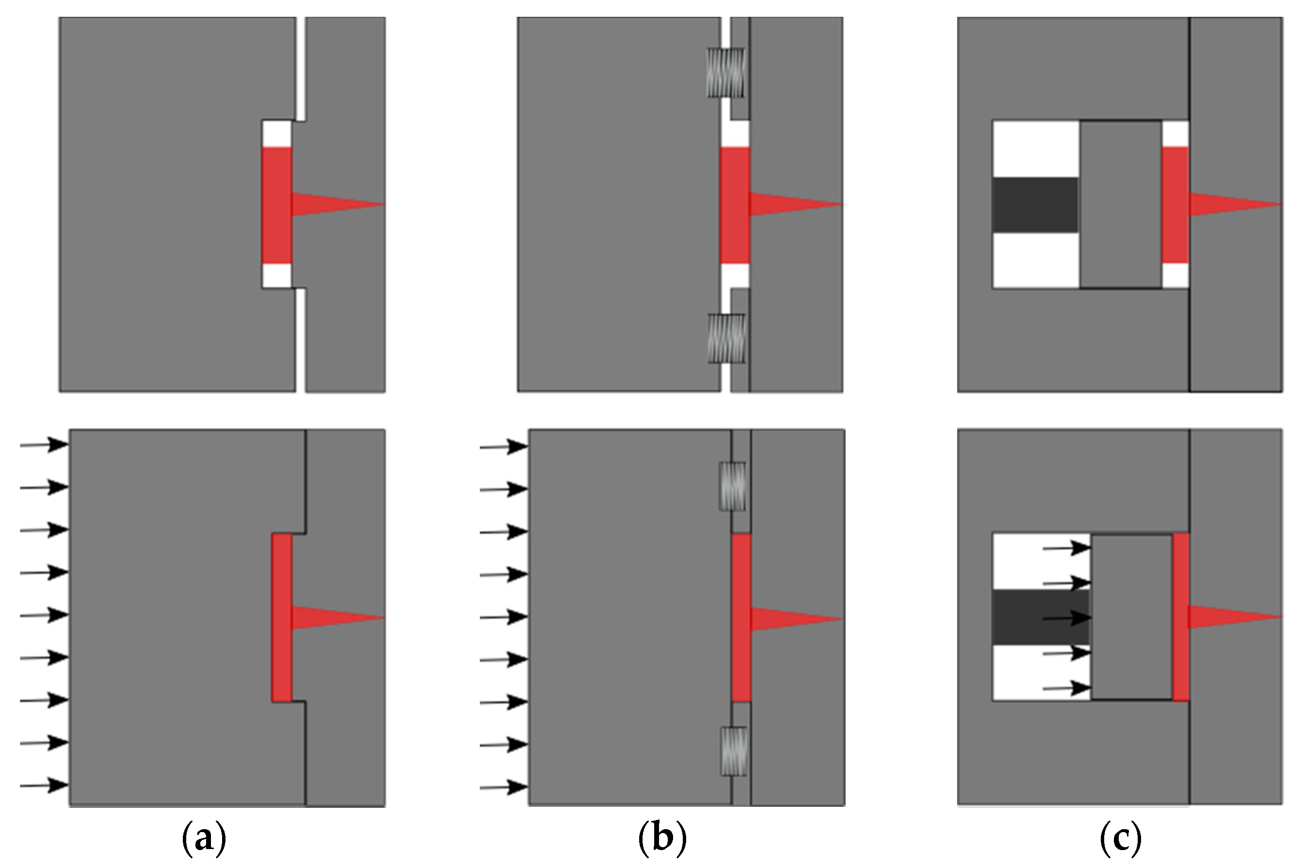
5]. The additional gap between the molds is called the compression gap, and it provides the necessary stroke to perform the compressing action. The compression gap is achieved in different ways. One of them consists of the design of molds with a so-called “vertical flash” area (see
Figure 1a), in which the entire mold halves are kept separated. Another option employs a “compression frame” into the mold. The frame is built with spring systems, and an additional compression plate is mounted into the movable mold side (see
Figure 1b). A more accurate but also more cost-intensive solution consists of the adoption of an independent “compression core” (see
Figure 1c). In this configuration, the insert in the movable cavity is directly actuated for cavity closure, and it performs the compression. The selection of the most suitable solution depends on cost, and partly on geometry and target accuracy. The compression action is seen as an additional holding phase that is applied to the material inside the cavity. In IM, holding starts at the so-called switch/over point, i.e., the moment when part filling is considered complete, and the machine control switch from a filling control criterion (injection velocity, screw position, injection pressure, etc.) to a holding control criterion, generally the holding pressure. Holding ensures that the final part volume is equal to the one of the cavity, since the polymer material shrinks during cooling. In IM, holding is consequently a crucial quality step; however, for parts showing long flow length and/or small wall thickness, the required holding pressure to compensate for the pressure drop can be significantly high, as are the resulting residual stresses inside the part. The major advantage of ICM consists of the opportunity to reduce stresses in the part, as compression action provides an in-thickness holding effect on the cavity, ensuring a uniform distribution of stresses inside the cavity, while the part solidifies [
6,
7,
8]. For this reason, ICM has been extensively favored to IM in the production of optical components. It is proven that it provides enhanced optical functionalities by reducing the birefringence and increasing the transmission efficiency, which are both correlated to the part internal stresses distribution. Birefringence effect is an optical property, which causes preferential light multiple refractions within the optics [
9,
10,
11]. At the same time, the light transmission measures the effective spectral and power transmittance of the optics, i.e., a combined result of the material absorption of specific wavelengths, reflection, and surface loss. All of these aspects are heavily dependent on the geometrical and dimensional optical design, and on local surface defects such as roundings or drafts that are natural outcomes of the molding process [
12,
13]. Even though ICM leads to functional benefits, the compression phase increases IM complexity, because additional parameters must be taken into consideration for optimizing the process. Suzuki et al. [
14] presented the importance of increasing the compression stroke in order to improve surface replication. On the contrary, Rohde et al. [
15] discouraged the increment of the compression gap, as it reduces the transcription ratio of micro-structures. These controversial results in relation to the compression gap require further consideration, and they have received attention in recent research. Masato et al. [
16] observed a significant interaction between the compression gap and the injection velocity, confirming that the optimization of the compression gap must take into account the overall polymer flow conditions. The study highlighted the negative impact of a large compression gap with respect to the replication homogeneity. A similar result was achieved by Chen et al. [
17], who proved that a smaller compression gap induces a more uniform part shrinkage, and in another study, Chen et al. [
18] validated that a larger compression gap increases part birefringence. The different theories regarding the compression gap selection can be justified by the results obtained by Shen et al. [
19]. In their work, replication and birefringence improvements were initially noticed by increasing the compression gap. Such a gain was due to a larger compression energy provided to the polymer melt that increased the shear rate and reduced the viscosity. However, the advantage arose from a delay in the compression phase, due to either a large compression gap, or a slow compression speed (or both), that increased the material viscosity as the polymer cooled down before being compressed, generating heat dissipation with the mold and shear rate reduction. In these conditions, the polymer melt front formed a thick solid layer, so-called “skin layer” on the mold wall, limiting the melt flow more than what the compression could favor. This theory was supported by Ho et al. [
20] observing an injection pressure and shear rate reduction with increased compression strokes. An additional result on compression parameters was given by Ito et al. [
21], who found that the compression starting point and the compression gap are relevant factors affecting both optical performance and internal stresses. The optimal compression start was identified when the cavity injection was completed. The work of Kuo et al. [
22] is one of the few studies mentioning the importance of the compression force. In the study, it was found that both IM and ICM parameters affect the replication of micro-features less when the compression force exceeds a certain threshold. Sortino et al. [
23] verified the influence on the transcription ratio of IM factors such as holding pressure, injection velocity, and mold temperature in ICM. Their study demonstrated that the statistical effect of the IM factors was reduced in ICM. A confirmation was given by Han et al. [
24], who discovered that the holding pressure could be reduced in ICM up to 50% with respect to IM, thanks to a more uniform cavity pressure distribution that is achieved with the compression phase. In the case of micro- or nano-structures replicated by ICM, a significant effect on the replication is also given by the mold temperature, as proved by Rytka et al., Nagato et al., and Chuan-Zhen et al. [
25,
26,
27]. The effective local mold temperature also supports different replication quality conditions in dependence on the cavity design and the polymer melt flow [
28,
29,
30]. Understanding the effective replication behavior of surface grooves is of paramount importance, to ensure the designed functionality of polymer optics, such as Fresnel lenses. Moreover, the complexity of the lenses’ features demands for dedicated quality control criteria. For example, the so-called “interference by adjacent step” is a Fresnel lens efficiency, loss due to its stepped discontinuous profile [
31]. In some cases, it is possible to reduce the efficiency loss by designing total internal reflection (TIR) lenses [
32,
33,
34]. However, molding-based processes are not always capable of reproducing the ideal design, e.g., because of minimum draft angles required for de-molding [
1]. In addition, the sharp edges of the micro-stepped grooves cannot be fully replicated, producing rounded features that reduce the overall optical performance [
35,
36,
37]. In general, functional optical tests based on photogrammetry ensure the correct optical functionality. Such tests are robust and investigate whether optical aberrations occur while operating the lens. From those results, it is possible to reconstruct the lens geometry when an optical model is available. Nevertheless, such tests do not distinguish whether aberration occurs due to material dependent degradation or geometrical/dimensional imperfections occurring in the manufacturing process. The identification of manufacturing signatures, i.e., the link between a measurable feature of the final part geometry and the individual manufacturing process conditions, allows for a comprehensive understanding of the production steps, and ensures effective and efficient optimization solutions [
38,
39].
Dedicated geometrical metrology is needed for the assessment of a manufacturing signature. Tactile measuring equipment is still extensively exploited, even though they can generate scratches on the lenses surface and generally require long set-up time and suffer accuracy loss in PV measurements [
40,
41]. Alternatively, non-contact optical solutions such as 3D optical microscopes can also be adopted for the scope [
42]. Nevertheless, the high transparency of the material prevents the possibility of using focus variation systems or contrast-based microscopes. Similar limitations of these techniques are observed when optical or near-optical surface roughness (i.e., down to single digits to tens of nanometers, respectively) is measured [
43,
44]. In addition, setting up a scatterometry-based inspection is challenging, as the tips and roots of the Fresnel surface severely manipulate the scattering properties of the specimen [
45]. In this study, the low aspect ratio surface micro-grooves of a Fresnel lens were investigated using a confocal microscope. The microscope principle is well known for its flexibility and the possibility to have both lateral and vertical resolutions in the sub-micrometer level. In this work, the identification of different manufacturing signatures in the production of Fresnel lenses is tackled. To do so, an initial metrological procedure with a detailed uncertainty budget is proposed, to evaluate the lens surface micro-feature replication. The methodology is proposed for two different materials, providing robust applicability for the procedure. The objective of this work is to provide a comprehensive methodology for the quantitative evaluation of IM and ICM performances, based on manufacturing signatures that address micro-replication quality. The four different manufacturing signatures (micro-replication accuracy, warpage, injection pressures, and part mass) were applied, providing a methodology for the optimization of IM and ICM. These four manufacturing signatures are employed, and their respective results are compared simultaneously as drivers of the optimization process for micro-structured optical parts manufacturing. The methodology, based on a metrological approach, provides a robust guideline for the effective molding of high precision polymer optics.

 ,
, 


