Abstract
Virtual Private LAN Services (VPLS) is an ethernet-based Virtual Private Network (VPN) service that provides multipoint-to-multipoint Layer 2 VPN service, where each site is geographically dispersed across a Wide Area Network (WAN). The adaptability and scalability of VPLS are limited despite the fact that they provide a flexible solution for connecting geographically dispersed sites. Furthermore, the construction of tunnels connecting customer locations that are separated by great distances adds a substantial amount of latency to the user traffic transportation. To address these issues, a novel Hierarchical VPLS (H-VPLS) architecture has been developed using 802.1Q tunneling (also known as Q-in-Q) on high-speed and commodity routers to satisfy the additional requirements of new VPLS applications. The Vector Packet Processing (VPP) performs as the router’s data plane, and FRRouting (FRR), an open-source network routing software suite, acts as the router’s control plane. The router is designed to seamlessly forward VPLS packets using the Request For Comments (RFCs) 4762, 4446, 4447, 4448, and 4385 from The Internet Engineering Task Force (IETF) integrated with VPP. In addition, the Label Distribution Protocol (LDP) is used for Multi-Protocol Label Switching (MPLS) Pseudo-Wire (PW) signaling in FRR. The proposed mechanism has been implemented on a software-based router in the Linux environment and tested for its functionality, signaling, and control plane processes. The router is also implemented on commodity hardware for testing the functionality of VPLS in the real world. Finally, the analysis of the results verifies the efficiency of the proposed mechanism in terms of throughput, latency, and packet loss ratio.
1. Introduction
After the emergence of Internet Protocol (IP) networks, Internet Service Providers (ISPs) looked for a proper solution to connect enterprises with private network services by using existing IP infrastructure [1,2]. To address this issue, Multi-Protocol Label Switching (MPLS) was developed. Providing private network over MPLS usually falls into two categories: MPLS Layer 3 VPN and MPLS Layer 2 VPN [3,4,5,6]. Virtual Private LAN Services (VPLS) combine the advantages of ethernet and MPLS to connect geographically dispersed LANs through IP/MPLS networks [7,8,9,10]. As a result, all network LANs can cooperate as a single LAN. This means that all messages are sent and received using source and destination Medium Access Control (MAC) addresses. By using VPLS, communications among LANs can be multipoint-to-multipoint, point-to-multipoint, and even point-to-point [3,11,12]. In other words, VPLS logically creates a layer two switch on the ISP side that each LAN with a different location connects to the virtual physical switch [11,13].
One of the many advantages of VPLS service is that it allows sites each with different broadcast domains to operate as if they are in a single big broadcast domain connected to big layer 2 switches. So far, VPLS is vendor-specific, which means that in order to support VPLS on a vendor’s device, the service provider should purchase VPLS modules that are only compatible with its own product, and also in this situation, it is unclear if the VPLS module is inter-operable with that of the device of other vendors located somewhere else. This gives us the inspiration to implement a vendor-agnostic VPLS on high-speed and commodity routers [4,12,14]. The development of new VPLS applications necessitates the incorporation of new operational needs, such as improved security, streamlined service provisioning, better network resource use, improved scalability, and autonomous network management support [15,16]. However, it is difficult for such functionality to be provided for new applications in the outdated VPLS architectures that are now in use.
When VPLS was first introduced, it was described as a flat design. Nevertheless, because a full mesh of Pseudo-Wires (PWs) was necessary, flat topologies encountered significant scaling problems in both the data and control planes for more extensive networks. The Hierarchical VPLS (H-VPLS) architecture was suggested as a solution to this problem [10]. By reducing the number of PWs, the H-VPLS design offers a workable solution to the scaling problem. One of the hierarchical versions is to use Software-Defined Network (SDN) structures. According to the authors of reference [17], SDN might be used to address the VPLS scalability issue where the control channel is the communication path between the control plane and the data plane.
FRRouting (simply FRR) [18] is an open-source control plane protocol suite for Linux and Unix platforms. It consists of various protocols and features, especially MPLS and Label Distribution Protocol (LDP) [19,20]. A system with FRR installed acts as a single router and can inter-operate seamlessly with routers of other vendors. In addition, Pseudo-Wire (PW) technology [21], based on a Layer 2 VPN Enabler, is tuned to transmit ethernet packets, and these packets are transferred independently of other users’ traffic on the customer’s private network. FRR, based on the Linux or Unix platform, makes the router use the kernel’s features. In fact, in this case, the kernel is the router’s data plane [22]. Having a Linux or Unix kernel as the data plane has some disadvantages. Firstly, Linux kernel does not support VPLS forwarding and secondly, the performance is quite low compared to the performance of other vendors’ products. Hence, we use Vector Packet Processing (VPP) [22,23,24,25] for our data plane. VPP is a fast network stack running in Linux Userspace on multiple architectures including x86. High performance, rich features, and modularity make developers integrate VPP with other products such as OpenStack and Kubernetes [25,26]. VPP is built on top of DPDK (Data Plane Development Kit) [27], a set of libraries and tools to accelerate packet processing workloads by offloading packet processing from kernel to user process [28]. Despite the fact that DPDK is fast in packet processing, it treats packets serially. But, on the contrary, VPP takes the batch processing approach with a single set of instructions. As a result, there will be no lower amount of cache misses [23,24]. Thus, due to the features provided in FRR and VPP for the VPLS control plane and data plane specifications, they are suitable alternatives since other open-source frameworks do not support either the VPLS control plane or data plane specifications.
Hence, we will cover one of the most efficient VPLS implementation scenarios in terms of scalability and simplicity, which allows the service provider to set a specific VLAN tag for each customer on the network. In fact, we use FRR as a control plane and VPP as a data plane. We manipulated both FRR and VPP separately to support VPLS. This means that if a customer adds a tag to their frames, the service provider will also add another tag called 802.1Q tunneling (Q-in-Q) to it [29]. In essence, service providers enable trunk connections to the customer at all branches and network connection centers, which would be virtually impossible to give discrepancies and interference, security issues, and additional load management. So, Cisco’s recommendation for such conditions is Q-in-Q tunnel [29]. Double Tagging helps the service provider encapsulate common VLAN tags in a dedicated VLAN. After that, we integrated them as a single VPLS service over high-speed routers [5,30,31]. In order to achieve the above-mentioned goals and also to implement the fundamental functions, we are inspired by important Internet Engineering Task Force (IETF) RFCs [32] such as 4762 [12], 4446 [33], 4447 [34], 4448 [9], and 4385 [35]. Afterward, we evaluated the proposed service including two Cisco 7600 series routers [36] as well as two high-speed Nexcom NSA 7136 routers [37] with three Cisco 3750-x series switches in the real world [38,39]. The major contributions of our work are listed as follows:
- Proposed a novel H-VPLS architecture that integrates FRR as the control plane and VPP as the data plane for router and switch design.
- Developed VPLS via Q-in-Q tunneling, which significantly enhances traffic engineering.
- Conducted a thorough review of existing VPLS configuration scenarios.
- Implemented the fundamental control plane and data plane functions by focusing on RFCs 4762 [12], 4446 [33], 4447 [34], 4448 [9], and 4385 [35].
- Demonstrated that VPP and FRR provide transparent multipoint-to-multipoint services and interoperability with other vendors’ products using VPLS.
2. Preliminary
In this section, we first present the concepts and terminologies, followed by the existing VPLS architectures.
2.1. VPLS Description
VPLS has emerged as the preferred networking option for industrial businesses to connect aging Supervisory Control and Data Acquisition (SCADA) and process control equipment over a common network. It is a VPN technology that securely connects provider networks and remote client locations using a tunnel called PWs to transport ethernet packets. VPLS networks operate at high speeds, are cost-effective compared to traditional VPN networks, and they are protocol-independent. As a result, VPLS has gained significant popularity in various application areas, ranging from industrial networks to mobile backhaul networks. In this model, PWs are used to provide seamless multipoint-to-multipoint connectivity while maintaining the privacy and security of the data transmitted over the network. Our proposed VPLS service model, as illustrated in Figure 1, comprises several components.
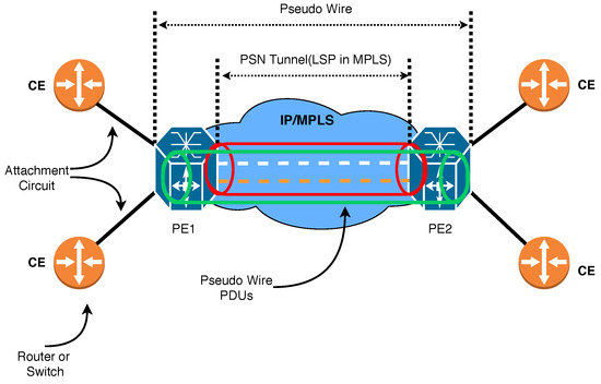
Figure 1.
Our proposed VPLS service model exhibiting PW significance.
- Customer Site
- Customer Edge device or simply CE: Customer network which is directly connected to the ISP.
- Provider Edge device or simply PE: This connects one or multiple CEs to the ISP. PE is responsible for converting IP to MPLS packets.
- Virtual Switch Instances or simply VSI: This is an ethernet bridge function entity of a VPLS instance on a PE. It forwards Layer 2 frames based on MAC addresses and VLAN tags.
- Network Provider device or simply P: ISP’s devices inside the core network which runs MPLS.
- PW signaling or simply PW: This is a bidirectional virtual connection between VSIs on two PEs. It consists of two unidirectional MPLS virtual circuits.
- Attachment Circuit or simply AC: The connection between CE and PE.
- The tunnel is a direct channel between PEs for data transmission. In this work, we use an MPLS tunnel.
A Packet Switched Network (PSN) tunnel must first be created between the two edge routers, and then a PW will be created inside the tunnel. The common physical link is called the Attachment Circuit [35]. As shown in Figure 2, the router can take the frame from two sides. When the router shares a frame from a shared physical link, it performs a MAC learning procedure just like a Bridge module.
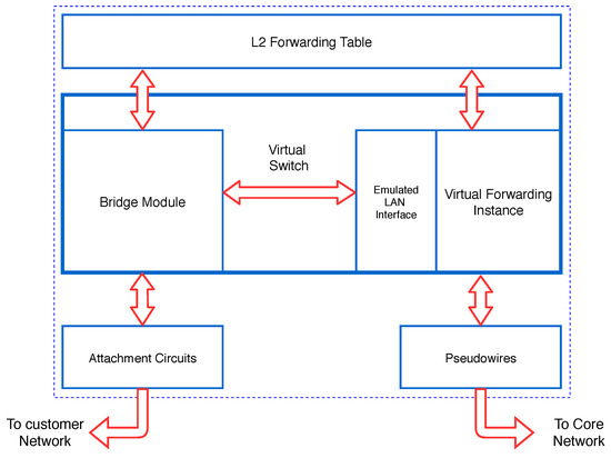
Figure 2.
Exhibiting the router’s sides to take frames when establishing tunnels [4,12].
When the router takes the frame from the network, it performs MAC Learning via PW (Virtual Forwarding Instance (VFI) operation). Regardless of whether the PE router carries out the MAC Learning from a shared physical link, it puts the MACs on a shared MAC table and performs the layer 2 Forwarding using the layer 2 Forwarding Table accordingly. So, when the router takes a frame from the shared physical link (Attachment Circuit), the MAC takes a MAP from the shared physical link. And when it takes a frame from the network, it writes the MAC Source to the frame to PW Label. As a result, when the frame reaches the router, it determines which PW package should be sent to the destination [12].
2.2. Existing VPLS Models
Generally, five configurations are recommended for VPLS implementation:
- Full mesh [40]: In this model, as shown in Figure 3, we apply a PW from each Provider Edge (PE) router to those of other PEs. To prevent Loop in this model, the Split horizon in layer 2 is run. A disadvantage of this model is that it will cause PW redundancy as the complexity of the network grows. Therefore, we see less implementation in practice.
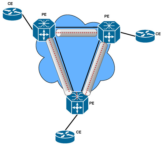 Figure 3. VPLS full mesh configuration in MPLS environment.
 - Hub and Spoke [40]: In this model, as shown in Figure 4, instead of having PW between all PE routers, PW is inserted between all PE routers with a central P router. The advantages of this model are the simplicity and lower number of PW required. Also, since there is no Redundant path, it makes a loop-free connection. The drawback of this model is the single point of failure because if the central router fails, all VPLS communications will fail. Therefore, this model is not implemented in the real world.
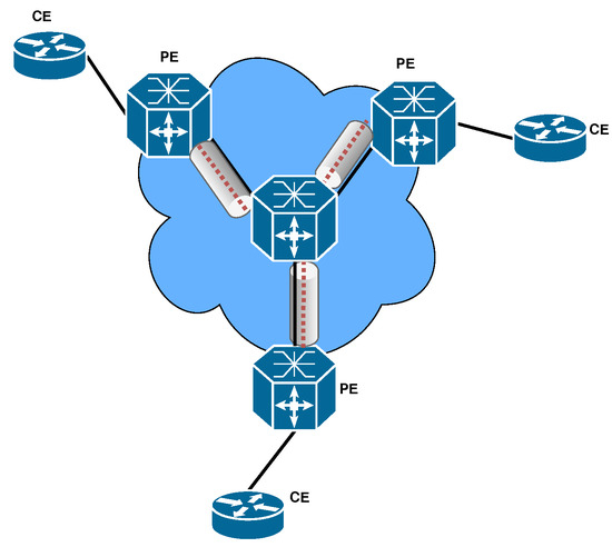 Figure 4. VPLS Hub and Spoke configuration in MPLS environment.
 - Partial Mesh [40]: This model, as shown in Figure 5, was created to add Redundancy to the Hub and Spoke model. Due to the structure of this model, we must disable the Split horizon, but due to having the Redundant path, we must activate Spanning Tree Protocol (STP). Since providers do not want to run STP on the network core, this model is also less common in practice.
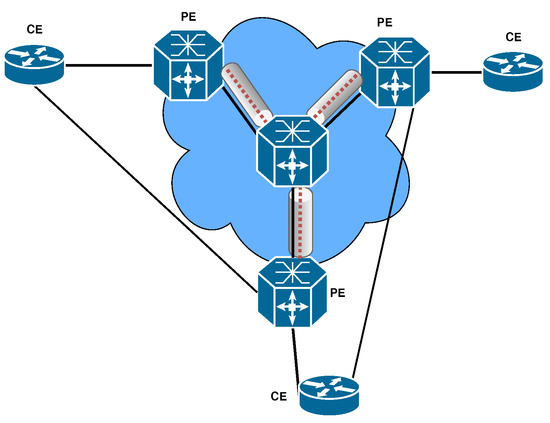 Figure 5. VPLS Partial mesh scenario configuration in MPLS environment.
 - H-VPLS with MPLS Access Network [40]: In this model, as shown in Figure 6, the network is divided into two parts, Top Tier with Full mesh, and Bottom Tier with Hub and Spoke. This architecture will reduce the number of PWs and will be a hierarchical model. The disadvantage of this model is the single point of failure. Since each of the U-PE routers is connected to the Top Tier network with a link, if this connection is corrupted or disconnected, the entire Bottom Tier connection of the Top Tier network will be disconnected.
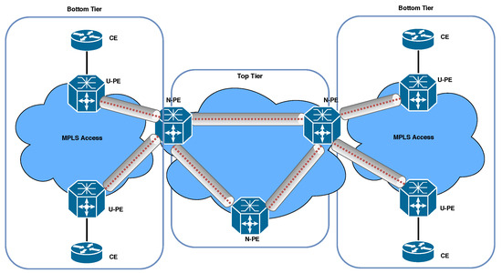 Figure 6. H-VPLS with MPLS access network configuration in MPLS environment.
 - H-VPLS with Q-in-Q Access Network: In the H-VPLS model proposed by the authors of reference [40], the Provider network is partitioned into ethernet-based islands, as depicted in Figure 7. These islands are interconnected using MPLS. Specifically, in the Bottom Tier of this architecture, PW Q-in-Q is utilized as the type of PW. The advantages of this topology, including easy availability through ethernet and hierarchical backing via Q-in-Q access, scalable customer VLANs (4K × 4K), and supporting 4K customers per access domain, have encouraged us to implement this model.
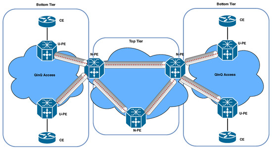 Figure 7. H-VPLS with QinQ access network configuration in MPLS environment.
3. Related Works
In this section, we delve into an exploration of recent advancements in VPLS and highlight their distinct characteristics.
When VPLS was initially proposed, it was described as possessing a flat topology that was well-suited for small to medium-sized networks [10,41]. However, these flat topologies encountered significant scaling challenges in both the data and control planes as larger networks necessitated a complete mesh of PWs. To mitigate this issue, the H-VPLS design was introduced as a viable solution by reducing the number of PWs and effectively addressing the scalability concerns [15]. In response to the early obstacles pertaining to scalability, security, and neighbor discovery, MPLS (Multiprotocol Label Switching) was employed instead of VPLS. Subsequently, the Border Gateway Protocol (BGP) and the Label Distribution Protocol (LDP) were suggested as two standard implementations for signaling and automatic neighbor detection [16]. Consequently, multiple architectural designs were proposed to enhance the operational capabilities of these frameworks.
The authors of reference [41] provide an in-depth analysis of VPLS and its design, elucidating its capabilities, such as MAC addressing, packet encapsulation, loop avoidance, auto-discovery, and signaling. They also briefly touch upon the advantages of H-VPLS over flat topologies. However, with the increase in users, scalability and security have emerged as critical concerns in VPLS. In reference [42], the architecture and applications of SDN are explained, while the authors of reference [43] explore novel approaches to enhance VPLS security and scalability, leveraging the potential of SDN. According to reference [42], SDN has the potential to address the scalability issues in VPLS. The communication path between the control plane and the data plane is referred to as the control channel, which is established using SDN control protocols. Network control functionalities and services are implemented as software applications in the application plane [17]. The controller sends flow entries to the data plane devices to govern their forwarding behavior, which is stored in local flow tables. If there is no matching entry, the packet is forwarded to the controller for further processing. In reference [17], an SD-VPLS architecture is described where each LAN is represented as an island, with the Island Controller responsible for controlling the OpenFlow switch, packet acceptance, and forwarding to the provider’s network.
The majority of VPLS topologies utilize MPLS as the underlying network infrastructure. MPLS acts as a virtual bridge within the network core, connecting various attachment circuits on each PE device and creating a unified broadcast domain [44]. BGP is a fundamental component of VPLS networks. BGP consists of speakers, peers, connections, and border routers. A BGP speaker is a host responsible for implementing the BGP protocol within the network. BGP peers are pairs of BGP speakers that establish connections and communicate with each other. An external BGP peer is located in a different autonomous system than the reference BGP speaker, while an internal BGP peer is within the same autonomous system [45]. Reliable BGP links are established using TCP. Signaling plays a crucial role in VPLS and involves the exchange of demultiplexers to establish and tear down PWs. Specific PW characteristics are transmitted during signaling, allowing a PE to establish a particular VPLS. Signaling occurs after the auto-discovery process is completed. The exchange of demultiplexers among PEs enables the transmission of update messages to other PEs in the same VPLS instance, thereby increasing the load on both the PE and the control plane [10]. MPLS relies on the agreement between LSRs on how to interpret labels, which is essential for forwarding traffic between and through LSRs. LDP is a set of protocols used for this purpose. Each LSR shares its bindings with other LSRs to ensure consistent label interpretation [12]. In VPLS, a PE acts as an edge router capable of executing LDP signaling and/or routing protocols to establish PWs. Additionally, a PE can create tunnels to communicate with other PEs and forward traffic through PWs.
Any modification to the VPLS topology, such as the addition or removal of a PE device, necessitates updating the configuration of every PE within that particular VPLS instance. In a flat VPLS architecture, the control plane is primarily responsible for auto-discovery and the establishment and termination of PWs. However, scalability issues can arise due to the requirement of a complete mesh of PWs between VPLS peers. Additionally, broadcasting messages to every speaker can impair the scalability of VPLS [46]. The hierarchical architecture of VPLS largely resolves scalability challenges. VPLS designs, such as H-VPLS and SD-VPLS, exhibit superior control plane scalability compared to flat systems, such as BGP-based VPLS and LDP-based VPLS. To enhance the scalability of VPLS, the authors of reference [47] proposed a method that enables the utilization of the same tunnels or PWs for multiple clients. In the data plane of VPLS, two key responsibilities are routing packets and encapsulating Ethernet frames. One significant scalability issue in the data plane is the MAC table explosion [12]. For instance, if each PE router is connected to N customer terminals for each service instance and there are M sites in the customer network, the total number of entries stored in each PE is N × M. When dealing with a large number of terminals (e.g., 25,000) and multiple locations (e.g., 10), each PE router would need to handle 250,000 entries. This quantity is typically beyond the capacity of most ethernet switches [48].
Several studies, including references [44,49], have investigated and compared the scalability of different VPLS implementations. Additionally, reference [50] proposed a scalable virtual Layer 2 implementation, and reference [6] suggested various methods to enhance the scalability of VPLS. Each of these studies is discussed below. In their work, the authors of reference [49] conducted a comparative analysis of the control plane scalability of L2VPN and L3VPN based on MPLS. This research examined and compared the performance of L2VPN and L3VPN using various metrics, including creation and deletion times, control plane memory usage, and overall memory usage. The findings of this study serve as a foundation for future scalability comparisons between traditional VPNs and their Software-Defined Networking (SDN)-based counterparts. Reference [50] proposed a scalable virtual Layer 2 implementation. Their study focused on analyzing the scalability of virtual Layer 2 for applications that utilize server clusters, such as data centers, as well as globally distributed applications. The research explored both hardware and software factors that can potentially impact VPLS compatibility. Given that VPLS deployments often involve equipment from different suppliers, compatibility issues may arise. To address this challenge, reducing reliance on vendor-specific hardware is crucial. These studies contribute to the understanding of VPLS scalability and propose solutions to address compatibility and performance issues. Future research in this area can build upon these findings to further enhance the scalability of VPLS deployments and explore the potential benefits of SDN-based approaches.
In general, the current H-VPLS architectures often involve complex network management. However, the use of the Q-in-Q technique presents an opportunity to extend VLANs across a service provider’s network by adding an extra VLAN tag to the primary ethernet frame. By combining VPLS with Q-in-Q tunneling, it becomes possible to create a virtual network that spans multiple sites and service provider networks [10]. Moreover, the combination of VPLS and Q-in-Q tunneling provides flexibility in network design and enables the integration of diverse network environments. Implementing and managing VPLS with Q-in-Q tunneling can be complex, requiring coordination between different network devices and service providers. Compatibility issues may arise, as the effectiveness of Q-in-Q tunneling can vary across different network equipment and vendors [40].
Therefore, our objective is to propose an innovative H-VPLS architecture utilizing Q-in-Q tunneling, specifically on high-speed and commodity routers, to meet the additional requirements posed by emerging VPLS applications.
4. Proposed Architecture
In this section, we elaborate on the overall design architecture, followed by demonstrating the relevant codes and pseudo codes. We have developed a novel H-VPLS architecture via Q-in-Q tunneling on high-speed and commodity routers to satisfy the additional requirements of new VPLS applications, in which VPP performs as the router’s data plane and FRR, an open-source network routing software suite, acts as the router’s control plane. On the other hand, the LDP is used for MPLS PW signaling in FRR. The basic and the most important incentive in implementing VPLS is the connection of multiple LANs with different geographical locations dispersed in WAN and the creation of an illusion that all of the sites see each other as if they are in the same LAN [4,12]. In this paper, as shown in Figure 8, the LDP provided by Cisco is used for PW signaling in our implementation. To receive packages at all label switched paths (LSPs) in the MPLS network, all LSRs must run LDP and exchange labels [19,28,33].
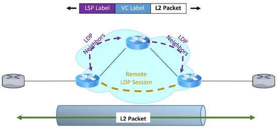
Figure 8.
LDP FRR configuration with MPLS PW signaling.
The use of IP routing protocols instead of the Spanning tree protocol and MPLS tags instead of VLAN identifiers in the infrastructure will significantly improve the development of the VPLS service. The difference between VPLS and L3VPN is in the Customer Edge (CE) side equipment.
4.1. Our Data Plane: VPP
VPP, which stands for Vector Packet Processing, is a framework from FDio foundation which provides out-of-the-box production quality switch and router functionality [23,24]. It is a fast, scalable, and consistent packet-processing stack that can run on commodity hardware. VPP comes with several useful features like high performance, avoiding context switch since it runs completely on user mode, no lock on the datapath, and modularity. VPP has a modular design, which means it allows users to attach new graph nodes without the need to alter its core. VPP runs completely on user space, so the forwarding performance, in this case, is several orders of magnitudes higher than that of the kernel. Preventing cache miss in the budget of the CPU cycle per packet ratio led to the formation of fast scalable VPP [23,24,30,51]. Another advantage of VPP is the ability to accomplish each atomic task in a committed node, process more than one packet at a time, and use vector instructions. The lack of some required services and the openness of many areas in development, including the API control plane, on the one hand, and a good framework for plugging, independent from the kernel with bridge implementation, and having a complete layer 2 and 3 networking stack, on the other hand, made us plug in a VPLS module in DPDK-based VPP [23,24,28].
It can switch up to 14 million packets per second (Mpps) per core without any packet loss, and it has a scalable and hierarchical Forwarding Information Base (FIB) which provides excellent performance and updates. It is optimized for commodity hardware, so it can take advantage of DPDK for fast I/O, and vector instructions such as SSE, AVX, and AVX2. It is optimized for instruction per cycle. Also, it runs on a multi-core platform, where the main concept would be batching packets. By batching packets, their processing is done at the same time, resulting in improved performance and reduced hardware costs. Additionally, this system runs on a multi-core platform, leading to better performance and increased efficiency. It also follows a “run to completion” mode. Some of the main features of VPP in each layer are: (i) L2: VLAN, Q-in-Q, Bridge Domains, LLDP; (ii) L3: IPv4, IPv6, GRE, VXLAN, DHCP, IPSEC, Discovery, Segment Routing; (iii) L4: TCP, UDP; and (iv) Control Plane: CLI, IKEv2.
As the VPP architecture is based on graph nodes, there are two types of nodes in VPP architecture: internal and input nodes [23]. Input nodes denote nodes that inject packets into the graph, whereas internal node denotes nodes that contain codes to run on packets. As shown in Figure 9, it is implied that the VPP graph is copied to each core inside the CPU and, on the memory side, VPP creates huge pages to accommodate more incoming packets. These packets then traverse the graph in a pipeline manner. The dispatch function in VPP takes up to 256 packets and forms them as a single vector element. When the first packet goes into the core, the l-cache gets warm by having the code of the first node inside it and, for the rest of the packets, there will be no cache misses for executing that node.
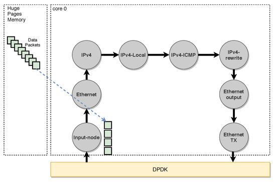
Figure 9.
VPP Graph [23].
There are a lot of workflow graphs for packet processing inside VPP, and also the user can attach their workflow to the main graph of VPP. The fundamental gain VPP brings is cache efficiency. In particular, there are two distinct caches: Instruction Cache and Data Cache. The former is for caching instructions and the latter is for caching data. According to Figure 10a, when the ethernet header is about to process, for the first time, the node which represents the ethernet header process instruction is transferred to the instruction cache due to cache miss. After that, for the rest of the headers, the instruction code will have remained in I-cache. After finishing the batch processing of the vector of packets, it is time for the processing of the IP headers (Figure 10b). Therefore, VPP batches IP headers and puts the vector inside D-Cache. At this time, the node which represents the instructions for processing the IP header is transferred to I-Cache due to cache miss. So, in essence, the cache miss for instructions is reduced significantly.
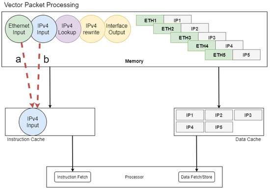
Figure 10.
VPP Process: (a) Ethernet header; (b) IP header [23].
4.2. Our Control Plane: FRR
The control plane is responsible for signaling and managing routing tables [5,52,53]. FRR is an open-source software stack on Berkeley Software Distribution (BSD)-based systems [18]. It is the control plane of many systems, such as virtual routers and white box switches. The FRR project is the continuation of Quagga (as an open-source project which implements routing stack) [54]. FRR itself, as a control plane, implements various kinds of routing algorithms on Linux Kernel as the data plane, and it is also inter-operable with other vendors’ systems such as Cisco, Juniper, and Huawei.
In traditional systems, the routing engine is made as one monolithic process which provides all of the functionalities required for routing [53]. But instead, FRR takes a quite different approach to implementation. As can be seen in Figure 11, each routing protocol in FRR (simply FRR) has a daemon. FRR consists of a set of daemons that collectively build the ultimate routing table and the forwarding table for the data plane. The interface between daemons and the data plane is another daemon called Zebra [18].
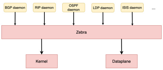
Figure 11.
FRR Architecture [18].
Daemons in FRR can be maintained by a single user interface called vtysh. vtysh connects to every daemon using the UNIX domain socket and acts as a proxy for user input.
4.3. Overall Design Architecture
As can be seen in Figure 12, the overall architecture is divided into Control Plane, Data Plane, kernel space, and hardware. FRR, as a control plane, and VPP + DPDK, as a data plane, are located in user space. However, the Network Interface Card (NIC) is completely in control of DPDK, therefore, the kernel will not be able to see or manipulate it [14,55]. The main details of this architecture should be mentioned, including Zebra and Router plugins. As shown in Figure 12, Zebra is used in FRR as a software-routing protocol to send messages between VPLS nodes. In fact, Zebra is used to manage the route and forwarding tables in VPLS, as well as routing messages sent between VPLS nodes. In addition, Zebra, as a routing protocol independent of the VPLS protocol, uses protocols such as OSPF or BGP as routing protocols for the network. In other words, Zebra manages routing tables between VPLSs using an OSPF or BGP protocol and then sends these tables to VPP so that VPP can send VPLS messages between VPLS nodes. The router plugin is also a tool used in VPP and it allows users to implement a VPLS service on one or more routers using this tool. This tool allows users to set routing parameters, such as default routes or routing protocols, for VPLS.
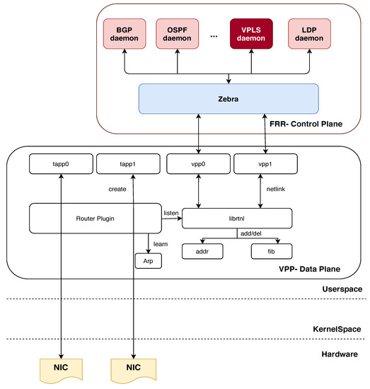
Figure 12.
Overall architecture of the H-VPLS design.
One of the advantages of the proposed architecture compared to existing hierarchical structures is that VPLS establishes communication between different devices directly without the need for layer three (routing). In other words, VPLS, using bridging technology, allows different devices in a local network to be seen as a single network independently of each other. In VPLS using VPP and FRR, this local network is managed using routing protocols such as OSPF or BGP. This method is simpler, less expensive, and does not require more powerful processing devices than the hierarchical structure. Also, the implementation of VPLS with VPP and FRR allows traffic between devices in a local network to be sent directly without the addition of intrusive routing protocols and at high speed. While in a hierarchical structure, traffic is transferred to another layer through routing protocols, and this can reduce network performance.
4.4. Implementation Phase
To implement VPLS using VPP and FRR, VPP must be installed on each switch. Then, using FRR, MPLS routing should be configured for the virtual LANs. Moreover, we need to configure VPLS on VPP. To do this, a VLAN for VPLS requires creation as well as a VFI for each switch. Moreover, we need to associate each VFI to a VLAN so that you can access the virtual LANs. Finally, we must define an MPLS label for each VFI so that one can communicate these VFIs together. To combine FRR and VPP to implement VPLS, we need to make some changes in the code of both projects. In particular, we need to change the FRR code so that it is compatible with the VPP and can receive VPLS messages from the VPP and, at the same time, we need to change the VPP code so that it can receive and process VPLS messages from the FRR. For example, in FRR we need to implement functions to send VPLS messages to VPP and, also in VPP, we need to implement functions to receive and process VPLS messages from FRR.
The pseudo-codes of the proposed service, as shown in Figure 12, can be described as the control plane and data plane, which are expressed as follows:
Control Plane (FRR): In this section, we explain the major implementation configuration in FRR [18] related to PW, including several functions as described below:
- Ldpd(): This function enables LDP on all active MPLS interfaces. LDP is used for distributing labels between PE routers and establishing LPSs in MPLS networks.
- L2vpn(): This function is responsible for creating, deleting, and updating PWs. PWs are used to provide point-to-point connectivity between two CE devices over a service provider’s MPLS network. L2VPN is a technology that enables the transport of Layer 2 traffic between different locations over an MPLS network.
- Ldpe(): This function sends hello packages periodically and creates sessions with other LDP neighbors. LDP neighbors are routers that are directly connected and exchange label information with each other. The hello packages are used to discover and establish LDP sessions with other routers.
- Lde(): This function is responsible for the distribution of marked labels. When an LSP is established between two routers, labels are assigned to the traffic that is being transported over the MPLS network. The LDE (Label Distribution Entity) is responsible for distributing these labels to other routers in the network.
In order to implement the proposed VPLS architecture in the FRR section, changes should be made in the codes related to L2VPN. In the L2vpn() section, VPLS-related functions should be added, including functions to create, delete, and update VPLSs, as well as VPLS database management functions. Also, we need to define VPLS parameters in LDP_Virtual teletype (VTY)_Configure file. For example, VLAN ID and VLAN mapping must be determined for VPLS. Moreover, the functions related to sending and receiving VPLS data in layer two (Layer 2) should be added to LDP. To achieve this, parts of the code related to L2TP (Layer 2 Tunneling Protocol) and MPLS message processing may be manipulated. In summary, the implementation configuration related to PW in FRR includes enabling LDP on all active MPLS interfaces, creating, deleting, and updating PWs, sending hello packages periodically, and distributing marked labels. These functions are essential for establishing and maintaining PW connectivity between CE devices over an MPLS network. In the FRR package, the ldpd directory contains the implementation code for the LDP daemon. The LDP daemon is responsible for managing the LDP protocol and establishing LSPs between routers in an MPLS network.
The LDP_Virtual teletype (VTY)_Configure file is a configuration file used to configure the LDP daemon. By activating L2vpn in this file, the LDP daemon is instructed to enable support for L2VPNs and to create, delete, and update PWs. In the code implementation, the LDP daemon is written in the C programming language. The LDP daemon source code is located in the ldpd directory of the FRR package. The ldpd code is organized into several files, including the following:
- ldpd.c: This file contains the main function for the LDP daemon. It sets up the LDP protocol, initializes the LDP database, and starts the LDP event loop.
- ldp_interface.c: This file contains the code for managing LDP interfaces. It handles interface events, such as interface up/down, and enables LDP on active MPLS interfaces.
- ldp_l2vpn.c: This file contains the code for managing Layer 2 VPNs. It handles the creation, deletion, and updating of PWs, and also manages the L2VPN database.
- ldp_ldp.c: This file contains the code for managing LDP sessions and exchanging label information with other LDP routers. It implements the LDP protocol and handles LDP messages.
- ldp_label.c: This file contains the code for managing LDP labels. It handles label distribution, label assignment, and label retention.
Overall, the ldpd directory in the FRR package contains the implementation code for the LDP daemon, which is responsible for managing the LDP protocol and establishing LSPs in an MPLS network. By activating L2vpn in the LDP_Virtual teletype (VTY)_Configure file, the LDP daemon is instructed to enable support for Layer 2 VPNs and to manage PWs. The implementation code is written in the C programming language and is organized into several files based on their functionality.
In the following, using LDP_Virtual teletype (VTY)_Configure file, and by activating L2vpn [56], the following sub-functions are called, which are summarized as follows:
Here, line 3 in Algorithm 1, PseudoWireType() is responsible for specifying the PW type based on the type given by the network administrator. The PW type is stored with a special code number Ethernet or Ethernet_tagged. DedicatedPseudoWire()—the interface and PW considered by the admin must be assigned. It must first be determined whether the interface and PW expressed have been used before. This is done by searching for the interface name in the existing l2vpn. If the PW ID or LSR ID was not previously used by another l2vpn, this PW will be removed from the passive PW list and assigned to the relevant l2vpn. PwNeighborAddr()—the address of the router that is neighboring the current router by PW must be assigned. The family from which the address is selected (ipv4 or ipv6) and the neighbor’s router address are given by the admin. Because these data are set by the admin, their flag is stored as static. PwNeighborId()—the router ID assigned to the current router by the PW is assigned. At the end line of Algorithm 1, PwIdAssign(), the router’s ID, which is dedicated to PW, is assigned.
| Algorithm 1 LDP _l2vpn_PWtype () |
Require: Enable L2vpn
|
In the l2vpn_Configure file, the following sub-functions are used inside the l2vpn function to perform the searches or changes needed to attach PW. Here, Line 2 of Algorithm 2, PwNew() creates PW given by the admin. PwFind(pw, InterfaceName) searches PW given by the admin in the corresponding tree. If there is such a PW to assign, we can activate it in the next steps if it is disabled and is assigned to l2vpn. In the following two functions, PwFindActive(pw) and PwFindinActive(pw), the active or inactive state of the given PW is specified. PwUpdateInfo(pw)—in the event of a new change, the index will be updated. PwInit(pw, fec) is called in ldpd(). When the LDE_ENGINE process is considered to run, PW information is transferred to the kernel. By calling PwExit(pw) in ldpd() function, the necessary updates about PW will be made. As shown in line 8 of Algorithm 2, two sub-functions appear:
Regarding kernel_remove(), when a path changes, zebra advertises the new path without removing the previous path. So another process has to be done in zebra to identify the next hop that has been removed along the way and remove the label from zebra. Regarding kernel_update(), recently deleted local tags should not be used immediately because this causes problems in terms of network instability. The garbage collector timer must be restarted and re-used when the network is stable.
Before calling PwNegotiate(nbr, fec) in line 19, the following steps 10–18 must be derived (by calling PwOk(pw, fec)): LSP formation towards the remote endpoint, tagging, size of MTU, and PW status. The validity of LSP formation is checked by zebra. However, if the PW status TLV is not supported in the remote peer, the peer will automatically delete this field. In this case, the PEs must call the process of discarding the label to change the signaling status.
According to RFC 4447 [34], if the PW status is not declared in the initial_label_mapping package, SendPwStatus(nbr, nm) returns the value of zero to execute the process of discarding the label. When changes are made to the PW flag, the new changes must be notified to the neighbors assigned by the lde. These changes are sent to each neighbor with notification messages. After receiving a notification message from the RecvPwStatus(nbr, nm) function, the recipient PE updates the tag to the correct value. If the PW has not been removed, then the related configurations are fixed, otherwise the package is discarded by calling RecvPwWildCard (nbr, nm, fec). If the pw status has changed from up to down, the assigned labels should be discarded from its neighbors’ table by calling PwStatusUpdate(l2vpn, fec). Contrarily, if it returns to the up status, it should be rewritten. However, in l2vpn defined with the help of PwCtl(pwctl), if PW is a subset of its member, the state of that PW sets to 1. By calling BindingCtl(fn, fec, pwctl), the tags specified in the label mapping for PW are bounded to the local and remote PW tags and, after running this function, the values of the PW tags are completely allocated.
In the 30th line of the algorithm, when admin defines an l2vpn configured file, it has received neighbor information and added those to its neighborhood table. This can be done using ldpe_l2vpn_init(l2vpn, pw) and ldpe_l2vpn_exit(pw). Additionally, by calling ldpe_l2vpn_pwexit(pw, tnbr), if the defined PW for l2vpn has already been used, the PW should be misdiagnosed and prevented from repeating.
| Algorithm 2 l2vpn_PW () |
|
In the ldpd()_Configuration file, if there is a change in l2vpn configuration, a new configuration will be made by inserting or deleting the variations.
Here, in line 4 of Algorithm 3, by calling MergeInterface(), the changes in the interface of an l2vpn file are checked so that if it is wasted, it will be removed from the database and released, and if it is not found, it will be registered in the database. In the MergeActivePw() function, if the active PW is wasted, it will be removed from the database and released. And in UpdateExistingActivePw(), if the LDP address is changed in a PW, it is sufficient that the target passengers are reinstalled, but under any of the following session conditions it must be changed.
If PW flags and configuration TLV status have changed, all neighbors must be reset. However, if PW type has changed most of the transfer unit, PW or LSR ID, the PW FEC must be reinstalled. Finally, calling MergeInActivePw() is like the description of active PW, except that the operation is performed on passive PW.
Finally, after applying the above algorithms, our control plane will be ready to provide the proposed service.
| Algorithm 3 Ldpd () |
|
Data Plane (VPP) In this section, we explain the algorithms implemented in VPP [23] as our fast data plane to create VPLS based on Python APIs. The logical process for VPLS code in the Data Plane Development Kit (DPDK) is as follows:
- Creation of l2 tunnel using the VppMPLSTunnelInterface algorithm;
- Addressing routes using VppMplsRoute;
- Bridge-domain using structured set_l2_bridge;
- Obtain the packages and address them;
- Packet encapsulation methods;
- Learning and forwarding part;
- The stream section of the packages in each direction;
- Disable Bridge domain after finishing work.
In the following, the above items are described along with the structure in the corresponding platform.
In (a) process: The VppMPLSTunnelInterface algorithm is called from the main algorithm VPP_Interface. The goal of this algorithm is to establish L2 on MPLS. First, the VPP_Interface algorithm is checked, then the VppMPLSTunnelInterface, and finally the VPP_Neighbor. The ABCMeta, util, and VPP_Neighbor items need to be imported into the VPP_Interface algorithm. The ABC item is used to establish infrastructure in Python to define abstract base algorithms (ABCs). ABCMeta is also used to define and create ABC. In the util item, it is necessary to activate the util algorithm to establish the test structure in vpp. The algorithm VPP_Interface creates vpp interfaces and related subjects. There are many properties defined in this algorithm, but the ones required for the VPLS service can include assigning index interfaces, selecting names for interfaces, and activating MPLS on the VPP interface. VppMPLSTunnelInterface itself imports the following: from vpp_ip_route import VppRoutePath and from VPP_Interface import VppInterface. The last item is the VPP_Neighbor algorithm. This algorithm is required to establish VPP_Interface. In Algorithm 4, we have the function of finding neighbors. It should be noted that this section works with inet_pton, inet_ntop, AF_INET, and AF_INET6 sockets. Here, the VppMPLSTunnelInterface code is as follows:
| Algorithm 4 VppMPLSTSTunnelInterface (VppInterface): |
|
In (b) process, by calling the vpp_ip_route algorithm, the routing is carried out. Before defining this function, the following rules must be satisfied:
- 1:
- {comment: # from vnet / vnet / mpls / mpls _types.h}
- 2:
- MPLS_IETF_MAX_LABEL = 0xfffff
- 3:
- MPLS_LABEL_INVALID = MPLS_IETF_MAX_LABEL + 1
This section sets the maximum label to 0xfffff and determines the value of the MPLS label. An important part of VPLS performance will depend on this, as the important VppMplsRoute function is defined in vpp_ip_route.
In Algorithm 5, the local label, EOS bit, and table ID are set. If the EOS bit is equal to one, this means that we will not have multiple labels. The route-finding function in line 10 is also defined.
| Algorithm 5 VppMplsRoute(VppObject): |
|
In process (c), the Bridge-domain section is applied using the vpp_papi_provider algorithm. All the APIs required for the users are available in this algorithm. Regarding VPLS, it is necessary to create or remove Bridge-domain interfaces. In this section, applying the sw_interface_set_l2_bridge configuration is sufficient.
(d) Packages are taken from the customer interface. The physical address and IP addresses of the packages should also be written in the configuration.
(e) Packet encapsulation: After section (d), the bridge domain learns and sends each packet. This post will be in capsule form. Functions such as add_stream() and enable_capture() from vpp_pg_interface must be applied and called. Adding streams from packets to VPP is achieved by the add_stream(). The ability to capture from the packet-generator interfaces is enabled by enable_capture().
(f) Forwarding: According to the Capturing packages in the previous section, we can move forward packages based on learning by applying the get_capture command. This function from vpp_pg_interface receives capture packets.
In the (g) and (h) sections, a stream of packets is sent in each direction. Finally, after the work is completed, the Bridge-domain interface can be disabled. To achieve this, in the sw_interface_set_l2_bridge function, it is sufficient to set the enable parameter to zero.
After applying the above processes, our data plane will be ready to provide the proposed service.
5. Simulation Results
In this section, we outline two test approaches: lightweight and practical scenarios. The lightweight scenario refers to the implementation of the proposed protocol on the software-based router in the Linux environment, through which we are trying to show the performance, signaling, and control plane processes. To the best of our knowledge, since we face simulation constraints at this level, we configured a high level of testing based on the practical scenario. At this level, the router is implemented on the commodity hardware to test the functionality of VPLS in the real world. Finally, based on the analysis of results, we evaluate the efficiency of this service in the three factors of throughput, latency, and packet loss ratio. Also, Table 1 demonstrates the test specifications.

Table 1.
Test specifications.
5.1. Lightweight Design and Test
In the topology, as shown in Figure 13, the two routers R1 and R2 are the two routers CE. Our Router Design (we called Rahyab as high-speed routers), frr-router-1, frr-router-2, and frr-router-3 routers also play the role of PE routers. In all three Rahyab routers, OSPF and MPLS mechanisms are activated [38]. However, VPLS (on the proposed specifications) is only enabled on PE routers 1 and 3. It should be noted that configuring Cisco routers is just for specifying the address of their ethernet link.
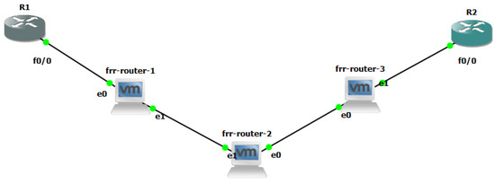
Figure 13.
Our lightweight H-VPLS simulation scenario.
The following are some instructions for the configurations performed in the lightweight scenario.
- The R1 and R2 router configuration are illustrated in Figure 14;
- Configurations for Rahyab router: The settings for the above scenario Figure 13 are given for each router as follows:1. Enable IP forwarding feature in Linux operating system that can be applied to both versions of IP.2. Enable MPLS on each interface.3. Define a new bridge and PW in the kernel.4. Enable bridge and PW.5. Connect the bridge and PW created in the previous section to the ethernet link. It is worth mentioning that the settings for steps 1 to 5 are done in the Command Line environment of Linux, and these settings are the same for all Rahyab routers.6. Turn on and give IP addresses to the interfaces, enable OSPF and MPLS, and perform configurations related to each of them (these are not explained in this document because they are thoroughly explained in other documents).7. Enable VPLS on PE routers (routers 1 and 3 in Figure 13). As a result of running the command, the following commands are activated under VPLS, and the interface ens32 and PW mpw0 are recognized as its members. By determining the address of the router connected to the other end of PW, the VPLS neighborhood of the current router is determined.
To ensure the accuracy of the VPLS and topology commands, we check the output of the binding and VC commands. For instance, the result of executing these two commands on router 3 will be as follows. If a binding is done correctly, each VC will be assigned a local tag and a round tag. Figure 15 confirms this goal.

Figure 14.
R1 and R2 configurations based on simulation scenario Figure 13. Settings according to sub-figures (a,b) should be considered.
Figure 14.
R1 and R2 configurations based on simulation scenario Figure 13. Settings according to sub-figures (a,b) should be considered.


Figure 15.
Results of lightweight H-VPLS scenario Figure 13. Settings according to sub-figures (a–e) should be considered.
Figure 15.
Results of lightweight H-VPLS scenario Figure 13. Settings according to sub-figures (a–e) should be considered.

Also, it can be seen in Figure 15e, if PW signaling works properly, the state of PW will be up.
According to our simulation, although the control plane works in this scenario, the data plane in PEs does not work since PEs employ bridges for transferring packets from one customer to another. Therefore, we decided to keep carrying out our experiment in the real world.
5.2. Practical Design and Test
VPLS has quite a complex implementation as it comprises several different protocols and services in order to provide remote layer-2 connectivity. Therefore, its implementation has a few steps, as shown below:
- A general routing protocol must be run in order for the routers to be reachable. We chose Open Shortest Path First (OSPF) as a dynamic routing protocol and ran it on PE1, PE2, PE3, and P routers. In this experiment, routers can reach each other by their associated router-id.
- MPLS and LDP should be configured correctly. MPLS and LDP are used for labeling packets and the distribution of the labels of each router, respectively. At this point in time, routers can reach other routers via MPLS labels rather than IP addresses.
- In this step, VPLS configuration must be applied on PE1, PE2, PE3, and also Q-in-Q tunnel. Moreover, switches should be configured in trunk mode and access VLAN mode as shown in Figure 16.
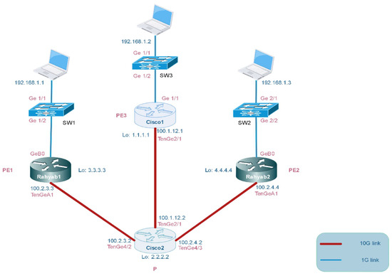 Figure 16. Our practical H-VPLS simulation scenario via Q-in-Q tunneling.
In this topology, the devices are connected according to Figure 16 to establish VPLS in the practical scenario which is based on a real-world scenario that can highlight the contribution of our work. In this test, the Rahyab1, Rahyab2, and Cisco1 routers are acting as PEs and the Cisco2 router is acting as P. Sw1, Sw2, and Sw3 switches are defined CE. All PE routers have VPLS connection configuration. Furthermore, we have changed the VLAN tag on the switches and defined them all as VLAN 100. The output link of the switches is set to the trunk port.
On PE routers, we consider the Q-in-Q tunnel tag to be 110. The purpose is to see if the ARP table of switches is able to learn the MAC address of the rest of the remote hosts, and the ability of the hosts to ping each other. In this scenario, Rahyab1 connects to Cisco1 by Virtual Circuit mpw3. Rahyab1 is labeled 21 for its local label, which means Rahyab1 sends its packets with label 21 to Cisco1. In addition, Rahyab1 is labeled 29 for its remote label which means Rahyab1 receives packets from Cisco1 with label 29. Therefore, Rahyab1 knows that these labels belong to Cisco1 by leveraging VPN id 110 and router-id 1.1.1.1. Finally, it can distinguish between packets received from Cisco1 or Rahyab2 based on local and remote labels and also router-id.
5.3. Measurements and Quantitative Outputs
In this sub-section, we demonstrate the quantitative measurements of our system based on three important parameters: Throughput, Latency, and Packet loss ratio. In this evaluation, Rahyab includes 16 interfaces with 1 Gbps and 6 interfaces with 10 Gbps; speed is directly connected to the Ixia tester [57] with the same specific interfaces. As is elaborated in Figure 17, the throughput of the router is considerably high in large frame sizes. Generally, there is an inverse relationship between throughput and frame size. In small frame sizes, there are many frames received in a second, and the router should process each frame. As a result, there will be a build-up of frame queues and it is likely that tail packets are dropped during packet processing. On the contrary, if the size of the frame is large enough, the processing and switching capacity of the router is sufficient enough to reach the maximum throughput.
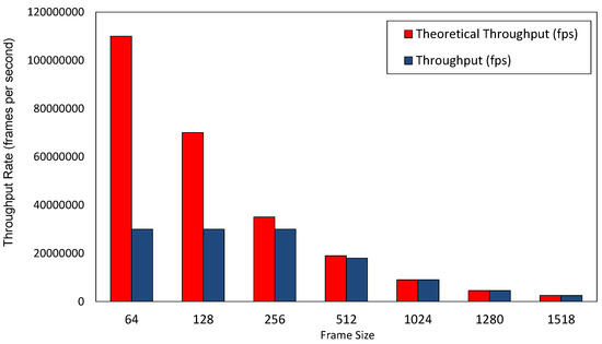
Figure 17.
Throughput rate per various frame sizes for our practical model.
In addition, as shown in Figure 18 and Figure 19, the average latency for small-sized frames is approximately in the same range (around 20 s), while the average latency for big-sized frames is around four times larger than that of small-sized frames. This is mainly due to the time it takes for the router to process large frames. The larger the size of frames, the more time it takes to process each frame and, as a result, there will be higher latency.
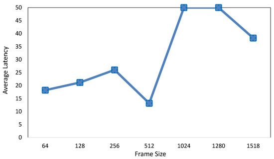
Figure 18.
Average latency per various frame sizes for our practical model.
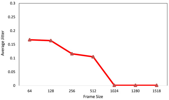
Figure 19.
Average jitter per various frame sizes for our practical model.
Moreover, the average amount of the small and big frames’ jitter is less than 1 μs, as shown in Figure 19. It is important to note that the average jitter for frames larger than 1024 bytes is, relatively, in the order of nanoseconds, which is three orders of magnitude smaller than that of small-sized frames. Moreover, as shown in Figure 20, we discussed queue build-up in small-sized frames. One of the causes of long queues is tail packet loss. Because the size of frames is short, there will be a huge number of incoming short frames, and as a result, they will create a long input queue and increase the probability of frame drop at the tail of the queue. The size of the frames can affect the distribution of traffic in the network. If frames of different sizes randomly enter the network, smaller frames (such as 64 and 128 bytes) may act as a noise load in the network and cause more interference, leading to an increased packet loss ratio.
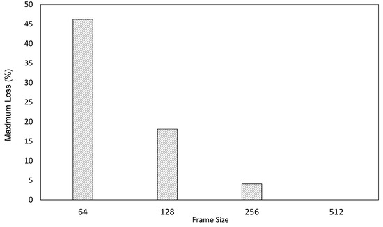
Figure 20.
Maximum packet loss ratio per various frame sizes for our practical model.
6. Conclusions
We developed a novel H-VPLS architecture via Q-in-Q tunneling on a commodity router. Our work is based on utilizing and enhancing two well-known open-source packages: VPP as the router’s fast data plane and FRR, a modular control plane protocol suite, to implement VPLS. Both VPP and FRR have active and dynamic communities, and they are the only open-source frameworks that support VPLS. FRR in the control plane implements control messages and relevant signaling, while VPP in the data plane side provides the capability of forwarding VPLS packets and manually labeling them. We have tested the implementation in both simulation and real physical scenarios, and the results indicate that the VPLS control plane works in compliance with the RFCs mentioned in the previous sections, as well as seamless interoperability with other vendors’ VPLS. Additionally, VPLS can be implemented in software without the need for specific support from the underlying hardware. Finally, the overall performance of the router shows that our proposed approach, based on open-source frameworks, is applicable in the real world.
In future work, we plan to test and compare the performance of our software-based VPLS with other vendors’ VPLS. There are two types of VPLS: H-VPLS-QinQ tunnel and H-VPLS-MPLS PW. As we have implemented the first type, we will also consider the design and implementation of the second type in future works.
Author Contributions
Conceptualization, software, methodology and writing—original draft: M.B.; Validation: M.B., H.F. and N.Y.; Visualization: M.B. and H.F.; Supervision: H.F. and N.Y.; Writing—review and editing: H.F. and N.Y. All authors have read and agreed to the published version of the manuscript.
Funding
This research received no external funding.
Data Availability Statement
The data that support the findings of this study are available from the corresponding author, upon reasonable request.
Conflicts of Interest
The authors declare no conflict of interest.
References
- Vallet, J.; Brun, O. Online OSPF weights optimization in IP networks. Comput. Netw. 2014, 60, 1–12. [Google Scholar] [CrossRef][Green Version]
- Bocci, M.; Cowburn, I.; Guillet, J. Network high availability for ethernet services using IP/MPLS networks. IEEE Commun. Mag. 2008, 46, 90–96. [Google Scholar] [CrossRef]
- Ben-Yacoub, L.L. On managing traffic over virtual private network links. J. Commun. Netw. 2000, 2, 138–146. [Google Scholar] [CrossRef]
- Sajassi, A. Comprehensive Model for VPLS. US Patent 8,213,435, 3 July 2012. [Google Scholar]
- Liyanage, M.; Ylianttila, M.; Gurtov, A. Improving the tunnel management performance of secure VPLS architectures with SDN. In Proceedings of the 2016 13th IEEE Annual Consumer Communications & Networking Conference (CCNC), Las Vegas, NV, USA, 9–12 January 2016; pp. 530–536. [Google Scholar]
- Liyanage, M.; Ylianttila, M.; Gurtov, A. Fast Transmission Mechanism for Secure VPLS Architectures. In Proceedings of the 2017 IEEE International Conference on Computer and Information Technology (CIT), Helsinki, Finland, 21–23 August 2017; pp. 192–196. [Google Scholar]
- Filsfils, C.; Evans, J. Engineering a multiservice IP backbone to support tight SLAs. Comput. Netw. 2002, 40, 131–148. [Google Scholar] [CrossRef]
- Bensalah, F.; El Kamoun, N. A novel approach for improving MPLS VPN security by adopting the software defined network paradigm. Procedia Comput. Sci. 2019, 160, 831–836. [Google Scholar] [CrossRef]
- Martini, L.; Rosen, E.; El-Aawar, N.; Heron, G. Encapsulation Methods for Transport of Ethernet over MPLS Networks. RFC4448, April 2006. Available online: https://www.rfc-editor.org/rfc/rfc4448 (accessed on 8 August 2023).
- Gaur, K.; Kalla, A.; Grover, J.; Borhani, M.; Gurtov, A.; Liyanage, M. A survey of virtual private LAN services (VPLS): Past, present and future. Comput. Netw. 2021, 196, 108245. [Google Scholar] [CrossRef]
- Hernandez-Valencia, E.J.; Koppol, P.; Lau, W.C. Managed virtual private LAN services. Bell Labs Tech. J. 2003, 7, 61–76. [Google Scholar] [CrossRef]
- Lasserre, M.; Kompella, V. IETF RFC 4762: Virtual Private LAN Service (VPLS) Using Label Distribution Protocol (LDP) Signaling. 2007. Available online: https://www.rfc-editor.org/rfc/rfc4762.html (accessed on 8 August 2023).
- Biabani, M.; Yazdani, N.; Fotouhi, H. REFIT: Robustness Enhancement Against Cascading Failure in IoT Networks. IEEE Access 2021, 9, 40768–40782. [Google Scholar] [CrossRef]
- Wirtgen, T.; Dénos, C.; De Coninck, Q.; Jadin, M.; Bonaventure, O. The Case for Pluginized Routing Protocols. In Proceedings of the 2019 IEEE 27th International Conference on Network Protocols (ICNP), Chicago, IL, USA, 8–10 October 2019; pp. 1–12. [Google Scholar]
- Liyanage, M.; Ylianttila, M.; Gurtov, A. Enhancing security, scalability and flexibility of virtual private LAN services. In Proceedings of the 2017 IEEE International Conference on Computer and Information Technology (CIT), Helsinki, Finland, 21–23 August 2017; pp. 286–291. [Google Scholar]
- Di Battista, G.; Rimondini, M.; Sadolfo, G. Monitoring the status of MPLS VPN and VPLS based on BGP signaling information. In Proceedings of the 2012 IEEE Network Operations and Management Symposium, Maui, HI, USA, 16–20 April 2012; pp. 237–244. [Google Scholar]
- Liyanage, M.; Ylianttila, M.; Gurtov, A. Software defined VPLS architectures: Opportunities and challenges. In Proceedings of the 2017 IEEE 28th Annual International Symposium on Personal, Indoor, and Mobile Radio Communications (PIMRC), Montreal, QC, Canada, 8–13 October 2017; pp. 1–7. [Google Scholar]
- The FRRouting Community. Available online: https://frrouting.org/ (accessed on 18 June 2020).
- Minei, I.; Marques, P.R. Automatic Traffic Mapping for Multi-Protocol Label Switching networks. U.S. Patent 10,193,801, 29 January 2019. [Google Scholar]
- Andersson, L. Technical Report, LDP Specification, RFC 5036. Minei, I., Thomas, B., Eds.; 2007. Available online: https://dl.acm.org/doi/abs/10.17487/RFC5036 (accessed on 8 August 2023).
- Stoll, D.; Thomas, W.; Belzner, M. The role of pseudo-wires for layer 2 services in intelligent transport networks. Bell Labs Tech. J. 2007, 12, 207–220. [Google Scholar] [CrossRef]
- Kaushalram, A.S.; Budiu, M.; Kim, C. Data-Plane Stateful Processing Units in Packet Processing Pipelines. U.S. Patent 10,523,764, 31 December 2019. [Google Scholar]
- Vector Packet Processing (VPP) Platform. Available online: https://wiki.fd.io/view/VPP (accessed on 18 June 2020).
- Linguaglossa, L.; Rossi, D.; Pontarelli, S.; Barach, D.; Marjon, D.; Pfister, P. High-Speed Data Plane and Network Functions Virtualization by Vectorizing Packet Processing. Comput. Netw. 2019, 149, 187–199. [Google Scholar] [CrossRef]
- Daly, J.; Bruschi, V.; Linguaglossa, L.; Pontarelli, S.; Rossi, D.; Tollet, J.; Torng, E.; Yourtchenko, A. Tuplemerge: Fast software packet processing for online packet classification. IEEE/ACM Trans. Netw. 2019, 27, 1417–1431. [Google Scholar] [CrossRef]
- Shukla, S.K. Low power hardware implementations for network packet processing elements. Integration 2018, 62, 170–181. [Google Scholar]
- Data Plane Development Kit. Available online: http://dpdk.org (accessed on 18 June 2020).
- Zhang, T.; Linguaglossa, L.; Gallo, M.; Giaccone, P.; Rossi, D. FloWatcher-DPDK: Lightweight line-rate flow-level monitoring in software. IEEE Trans. Netw. Serv. Manag. 2019, 16, 1143–1156. [Google Scholar] [CrossRef]
- IEEE Std 802.1 Q-2011; IEEE Standard for Local and Metropolitan Area Networks—Media Access Control (MAC) Bridges and Virtual Bridge Local Area Networks. IEEE SA: Piscataway, NJ, USA, 2011; Volume 31, p. 1365.
- Barach, D.; Linguaglossa, L.; Marion, D.; Pfister, P.; Pontarelli, S.; Rossi, D. High-speed software data plane via vectorized packet processing. IEEE Commun. Mag. 2018, 56, 97–103. [Google Scholar] [CrossRef]
- Liyanage, M.; Ylianttila, M.; Gurtov, A. Secure hierarchical VPLS architecture for provider provisioned networks. IEEE Access 2015, 3, 967–984. [Google Scholar] [CrossRef]
- Standard IETF RFCs. Available online: https://www.ietf.org/standards/rfcs/ (accessed on 18 June 2020).
- Martini, L. ÂIANA Allocations for Pseudo Wire Edge to Edge Emulation (PWE3) Â. Technical Report, RFC 4446. 2006. Available online: https://datatracker.ietf.org/doc/html/rfc4446 (accessed on 8 August 2023).
- Martini, L.; Rosen, E.; El-Aawar, N.; Smith, T.; Heron, G. RFC 4447: Pseudowire Setup and Maintenance Using the Label Distribution Protocol (LDP). The Internet Society. 2006. Available online: https://www.rfc-editor.org/rfc/rfc8077 (accessed on 8 August 2023).
- Bryant, S.; Swallow, G.; Martini, L.; McPherson, D. Pseudowire Emulation Edge-to-Edge (PWE3) Control Word for Use over an MPLS PSN. IETF RFC4385. 2006. Available online: https://patents.google.com/patent/US10523764B2/en?oq=US+Patent+10%2c523%2c764 (accessed on 8 August 2023).
- Cisco. Available online: https://www.cisco.com/ (accessed on 18 June 2020).
- Nexcom. Available online: https://www.nexcom.com/ (accessed on 18 June 2020).
- Manzoor, A.; Hussain, M.; Mehrban, S. Performance Analysis and Route Optimization: Redistribution between EIGRP, OSPF & BGP Routing Protocols. Comput. Stand. Interfaces 2020, 68, 103391. [Google Scholar]
- Holterbach, T.; Bü, T.; Rellstab, T.; Vanbever, L. An open platform to teach how the internet practically works. ACM SIGCOMM Comput. Commun. Rev. 2020, 50, 45–52. [Google Scholar] [CrossRef]
- Tiso, J.; Hutton, K.T.; Teare, D.; Schofield, M.D. Designing Cisco Network Service Architectures (ARCH): Foundation Learning Guide; Cisco Press: Indianapolis, IN, USA, 2011. [Google Scholar]
- Dong, X.; Yu, S. VPLS: An effective technology for building scalable transparent LAN services. In Network Architectures, Management, and Applications II, Proceedings of the Asia-Pacific Optical Communications, Beijing, China, 7–11 November 2004; SPIE Digital Library: Bellingham, WA, USA, 2005; Volume 5626, pp. 137–147. [Google Scholar]
- Xia, W.; Wen, Y.; Foh, C.H.; Niyato, D.; Xie, H. A survey on software-defined networking. IEEE Commun. Surv. Tutor. 2014, 17, 27–51. [Google Scholar] [CrossRef]
- Ahmad, I.; Namal, S.; Ylianttila, M.; Gurtov, A. Security in software defined networks: A survey. IEEE Commun. Surv. Tutor. 2015, 17, 2317–2346. [Google Scholar] [CrossRef]
- Palmieri, F. VPN scalability over high performance backbones evaluating MPLS VPN against traditional approaches. In Proceedings of the Eighth IEEE Symposium on Computers and Communications—ISCC 2003, Kiris-Kemer, Turkey, 30 June–3 July 2003; pp. 975–981. [Google Scholar]
- Rekhter, Y.; Li, T.; Hares, S. A Border Gateway Protocol 4 (BGP-4). Technical Report. 2006. Available online: https://www.rfc-editor.org/rfc/rfc4271 (accessed on 8 August 2023).
- Khandekar, S.; Kompella, V.; Regan, J.; Tingle, N.; Menezes, P.; Lassere, M.; Kompella, K.; Borden, M.; Soon, T.; Heron, G.; et al. Hierarchical Virtual Private LAN Service; Internet Draft; IETF: Wilmington, DE, USA, 2002. [Google Scholar]
- Martini, L.; Sajassi, A.; Townsley, W.M.; Pruss, R.M. Scalable Virtual Private Local Area Network Service. U.S. Patent 7,751,399, 6 July 2010. [Google Scholar]
- Chiruvolu, G.; Ge, A.; Elie-Dit-Cosaque, D.; Ali, M.; Rouyer, J. Issues and approaches on extending Ethernet beyond LANs. IEEE Commun. Mag. 2004, 42, 80–86. [Google Scholar] [CrossRef]
- López, G.; Grampín, E. Scalability testing of legacy MPLS-based Virtual Private Networks. In Proceedings of the 2017 IEEE URUCON, Montevideo, Uruguay, 23–25 October 2017; pp. 1–4. [Google Scholar]
- Dunbar, L.; Mack-Crane, T.B.; Hares, S.; Sultan, R.; Ashwood-Smith, P.; Yin, G. Virtual Layer 2 and Mechanism to Make Iit Scalable. U.S. Patent 9,160,609, 13 October 2015. [Google Scholar]
- Fahad, M.; Khan, B.M.; Bilal, R.; Young, R.C.; Beard, C.; Zaidi, S.S.H. Multibillion packet lookup for next generation networks. Comput. Electr. Eng. 2020, 84, 106612. [Google Scholar] [CrossRef]
- Valenti, A.; Pompei, S.; Matera, F.; Beleffi, G.T.; Forin, D. Quality of service control in Ethernet passive optical networks based on virtual private LAN service technique. Electron. Lett. 2009, 45, 992–993. [Google Scholar] [CrossRef]
- Peter, S.; Li, J.; Zhang, I.; Ports, D.R.; Woos, D.; Krishnamurthy, A.; Anderson, T.; Roscoe, T. Arrakis: The operating system is the control plane. ACM Trans. Comput. Syst. (TOCS) 2015, 33, 1–30. [Google Scholar] [CrossRef]
- Quagga Is a Routing Software Suite. Available online: https://www.quagga.net/ (accessed on 18 June 2020).
- Lim, L.K.; Gao, J.; Ng, T.E.; Chandra, P.R.; Steenkiste, P.; Zhang, H. Customizable virtual private network service with QoS. Comput. Netw. 2001, 36, 137–151. [Google Scholar]
- Dhaini, A.R.; Ho, P.H.; Jiang, X. WiMAX-VPON: A framework of layer-2 VPNs for next-generation access networks. IEEE/OSA J. Opt. Commun. Netw. 2010, 2, 400–414. [Google Scholar] [CrossRef]
- Ixia Tester. Available online: https://www.ixiacom.com/solutions/network-test-solutions (accessed on 18 June 2020).


Disclaimer/Publisher’s Note: The statements, opinions and data contained in all publications are solely those of the individual author(s) and contributor(s) and not of MDPI and/or the editor(s). MDPI and/or the editor(s) disclaim responsibility for any injury to people or property resulting from any ideas, methods, instructions or products referred to in the content. |
© 2023 by the authors. Licensee MDPI, Basel, Switzerland. This article is an open access article distributed under the terms and conditions of the Creative Commons Attribution (CC BY) license (https://creativecommons.org/licenses/by/4.0/).