Article

Integrated Systems Ontology (ISOnto): Integrating Engineering Design and Operational Feedback for Dependable Systems

1
School of Computing and Engineering, University of Bradford, Bradford BD7 1DP, UK
2
SAFI Verse Limited, Bradford BD16 4DR, UK
3
Valeo, 75017 Paris, France
*
Author to whom correspondence should be addressed.
Computers 2025, 14(11), 451; https://doi.org/10.3390/computers14110451
Submission received: 16 September 2025 / Revised: 11 October 2025 / Accepted: 18 October 2025 / Published: 22 October 2025
(This article belongs to the Special Issue Recent Trends in Dependable and High Availability Systems)

Abstract

This paper proposes an integrated ontological framework, Integrated Systems Ontology (ISOnto), for dependable systems engineering by semantically linking design models with real-world operational failure data. Building upon the recently proposed Function–Behaviour–Structure–Failure Modes (FBSFM) framework, ISOnto integrates early-stage design information with field-level evidence to support more informed, traceable, and dependable failure analysis. This extends the semantic scope of the FBSFM ontology to include operational/field feedback from warranty claims and technical inspections, enabling two-way traceability between design-phase assumptions (functions, behaviours, structures, and failure modes) and field-reported failures, causes, and effects. As a theoretical contribution, ISOnto introduces a formal semantic bridge between design and operational phases, strengthening the validation of known failure modes and the discovery of previously undocumented ones. Developed using established ontology engineering practices and formalised in OWL with Protégé, it incorporates domain-specific extensions to represent field data with structured mappings to design entities. A real-world automotive case study conducted with a global manufacturer demonstrates ISOnto’s ability to consolidate multisource lifecycle data into a coherent, machine-readable repository. The framework supports advanced reasoning, structured querying, and system-level traceability, thereby facilitating continuous improvement, data-driven validation, and more reliable decision-making across product development and reliability engineering.

1. Introduction

Modern engineered systems, particularly vehicles, face unprecedented complexity as they integrate advanced electronics, software, and connectivity. This complexity magnifies the risk of failures, which in turn can lead to costly recalls, warranty claims, and loss of customer trust. Ensuring dependability across the product lifecycle has therefore become a strategic priority for manufacturers. To meet this challenge, industry increasingly seeks predictive, data-driven methods that can link design assumptions with in-service performance.
The automotive industry is advancing towards more autonomous, intelligent, and reliable vehicle platforms by adopting predictive engineering practices. These practices utilise digital technologies to anticipate failures, reduce downtime, and optimise system performance across product lifecycle stages [1,2]. As modern vehicles incorporate increasingly complex electronic and software systems [3], the role of information and communication technologies (ICT) becomes critical for managing data across design, production, and deployment phases [4].
In alignment with Industry 4.0, the Automotive Healthcare Analytics Factory (AHAF) [5] model offers a structured approach for lifecycle-focused, data-driven decision-making. AHAF integrates descriptive, predictive, and prescriptive analytics to manage system knowledge across the lifecycle. However, the successful implementation of such a vision hinge on the ability to integrate design models with operational data in a semantically coherent way.
One of the key practices during the design phase is Failure Modes and Effects Analysis (FMEA), a structured technique for identifying potential failure scenarios and assessing their consequences [6,7], but in practice, it is often manually performed, loosely coupled with system models, and rarely updated with field data. This leads to inconsistencies and limited traceability, restricting the reuse of knowledge in future designs [8,9,10,11]. Model-based systems engineering (MBSE) has improved alignment between design and risk analysis [12,13], but challenges remain, particularly around tool interoperability, inconsistent data semantics, and limited support for reasoning across lifecycle stages [14,15].
Increasingly, operational data such as warranty returns, and service records are seen as essential for validating FMEA assumptions and improving future designs [16,17,18]. However, this field data is rarely integrated into formal design knowledge structures, leaving a critical gap in feedback loops between real-world performance and design intent.
In parallel, various ontological models have been developed to formally represent system knowledge. Models such as Function–Behaviour–Structure (FBS) [19,20], Function–Behaviour–State [21], and Structure–Behaviour–Function [22] have been proposed to support reasoning about design elements and their interrelations. Among them, the FBS ontology is particularly suited to the decomposition and traceability of design intent, making it a valuable foundation for modelling the relationships between system functions, expected behaviours, and physical structure.
Recent research has also applied artificial intelligence (AI) to enhance FMEA execution, using machine learning to identify, calculate, and evaluate risks more effectively [23,24]. While AI improves speed and accuracy, explainability remains a key requirement, especially in safety-critical industries like automotive. Ontologies offer a structured means to align AI-generated insights with engineering rationale, supporting human interpretability and decision-making [25].
In the field of ontology-based FMEA, prior work has focused on improving knowledge reuse, extracting insights from unstructured documents, and translating maintenance data into structured formats [26,27,28]. However, these efforts remain primarily confined to either the design or operational domains. The integration of field feedback with formal design ontologies, particularly those grounded in FBS principles, remains an underexplored area.
Although FBS-based ontologies have shown potential in supporting model-based failure reasoning [29], they typically operate in isolation from operational insights. Existing FBSFM [29] frameworks are limited to the early design phase and lack mechanisms for validating failure assumptions against in-field performance data. As a result, lifecycle traceability, adaptive risk modelling, and feedback-driven design refinement remain fragmented.
This paper addresses these limitations by proposing the Integrated Systems Ontology (ISOnto) to semantically integrate real-world operational data into early design models. ISOnto introduces a dedicated Field Feedback Ontology, derived from warranty data, and links it to the FBSFM structure to enable two-way semantic traceability between design intent and in-field failure observations. This solves a critical problem in current practices: the inability to formally relate actual failure data to design-phase assumptions, resulting in delayed updates to risk models and the limited reuse of operational knowledge.
Through a real-world automotive case study, this work demonstrates how ISOnto enables knowledge-driven diagnostics, cross-phase failure reasoning, and the enhanced reuse of system development insights. The results highlight the framework’s potential to close the feedback loop between product design and operational performance, providing a foundation for intelligent, adaptive risk analysis across the full span of system development and use.
The main contribution of this paper is the development and validation of the ISOnto framework that integrates FBSFM design knowledge with field feedback data to enable formal traceability, automated reasoning, and continuous improvement in dependability analysis.
The remainder of this paper is structured as follows. Section 2 reviews the related literature on FMEA, field data integration, and ontology-driven approach. Section 3 presents the methodology and development of the ISOnto framework. Section 4 details its implementation and validation through an industrial case study. Section 5 discusses the results, compares ISOnto with alternative approaches, and reflects on its implications. Finally, Section 6 concludes the paper and outlines future research directions.

2. Background and Related Work

2.1. FMEA Integration Within Systems Engineering: A Review of Methods and Challenges

Failure Modes and Effects Analysis (FMEA) remains one of the most established methods for ensuring system reliability and safety. As a proactive tool, it identifies, evaluates, and mitigates potential failure modes to support reliable, cost-effective, and environmentally sustainable designs [30]. Widely adopted across aerospace, automotive, and nuclear industries, FMEA follows standards such as SAE-J1739 [31] and IEC 60812 [32], and its flexibility enables applications in the hardware, software, human, and process domains, resulting in design, process, and system variants [6].
Two principal strategies guide FMEA implementation: the bottom-up approach (IEC 60812 [32]), which identifies component-level failures and traces their propagation upwards and is effective but reactive, and the top-down approach (AIAG–VDA [6]), which begins at the system level and cascades risks downwards to define preventive actions. Integration of FMEA into systems engineering ensures consistency between design intent and risk analysis, enhancing design robustness and reducing late-stage revisions [33]. Campean et al. [34] and Henshall et al. [35] advanced this integration through a function-oriented framework linking FMEA activities with system modelling to maintain traceability across design stages.
Further research has explored embedding FMEA within model-based systems engineering (MBSE). Huang et al. [9,14] examined model-based FMEA representations but highlighted limitations in automation and interoperability. Hecht et al. [36] and Girard et al. [37] proposed MBSE-driven FMEA generation methods, though practical adoption remains limited. Ontology-based approaches, such as Day et al. [38], sought to formalise failure reasoning but face scalability and implementation challenges, consistent with findings by Campean [39] and Henshall et al. [35] regarding inconsistent FMEA deployment across OEMs.
Frameworks like the Functional Failure Identification and Propagation (FFIP) method [40] enable early qualitative hazard analysis with minimal design input, typically requiring complementary methods such as FTA or PRA for quantitative validation. Mansoor et al. [41] proposed a backward failure propagation method to trace causal dependencies in abstract models, though accuracy depends on detailed data availability.
Efforts to formalise failure reasoning in knowledge-based systems include Russomanno et al. [42], who embedded FMEA in a blackboard architecture, and Tumer and Stone [43], who introduced the Function–Failure Mode Matrix Method, later extended by Stone et al. [44] into the Function–Failure Design Method (FFDM) for conceptual design risk analysis. While promising, these methods often lack lifecycle traceability and operational context, limiting their effectiveness for continuous, closed-loop risk management.
Persistent challenges constrain the effective integration of FMEA into complex modern systems including:
  • High system complexity: Managing interactions among numerous subsystems [29].
  • Data integration: Synthesising data from CAD models, simulation environments, and test results into coherent FMEA structures [16].
  • Multidisciplinary collaboration: Harmonising mechanical, electrical, and software domains within a single failure reasoning framework [45].
  • Interface management: Capturing and reasoning about the interactions and dependencies between system interfaces [35].
Addressing these challenges demands a multilayered solution that unifies formal system modelling with risk semantics, ensures lifecycle traceability, and incorporates operational feedback for adaptive, model-driven failure reasoning. These challenges highlight the need for complementary sources of evidence that can validate or refine design-phase assumptions.

2.2. Real-World Field Data as a Validation Source for Risk Assessment in the Design Phase

Spreafico et al. [46] reviewed 329 studies (1978–2016) and identified four enduring challenges that hinder FMEA’s practical application:
  • Applicability: FMEA is resource-intensive, reliant on user expertise, and difficult to apply to complex, multidisciplinary systems. Issues such as limited tool interoperability, constrained data handling, and poor collaboration further restrict its effectiveness.
  • Cause–effect relationships: Practitioners often struggle to define and trace interactions between failure types, causes, and effects, particularly when determining appropriate levels of analysis granularity.
  • Risk analysis: Inconsistent evaluation criteria, subjective prioritisation, and ambiguous action guidelines lead to variable outcomes.
  • Problem solving: Despite its analytical intent, FMEA frequently lacks clear objectives, structured solution pathways, and measurable outputs, weakening its decision-support capability.
With increasing system complexity, especially in the automotive and manufacturing domains, automation and artificial intelligence (AI) have become essential for enhancing FMEA efficiency and reducing human error [24,47]. Recent work integrates AI, machine learning (ML), and computer-aided engineering (CAE) to improve analytical depth and consistency [48,49]. For instance, Hecht et al. [36] developed an automated SysML–AltaRica-based FMEA generation method within an MBSE framework, while Girard et al. [37] implemented an MBSE–MBSA workflow using the smartIflow Workbench to support early design validation.
Machine learning and large language models (LLMs) have also been used to automate tasks such as failure identification and risk priority number (RPN) computation. El Hassani et al. [47] demonstrated a human-in-the-loop ML approach, while Sader et al. [50] trained models on 1532 failure reports, achieving high accuracy (precision 86.6–93.2%, recall 67.9–87.9%, F1 score 0.765–0.892). Similarly, Gheraibia et al. [51] developed an ML-based real-time safety monitoring framework for aircraft fuel systems, illustrating applicability in safety-critical environments.
However, automated systems still face key limitations. They struggle to capture dynamic interactions among failure types, environmental conditions, and human factors [48], and their performance depends heavily on the completeness and quality of input data [49]. Semantic variability in expert language also complicates natural language processing (NLP)-based FMEA, producing inconsistent outputs [11]. Moreover, automation may overlook contextual insights that typically arise from collaborative review processes intrinsic to traditional FMEA.
To mitigate these challenges, probabilistic and data-driven methods have been proposed. Brahim et al. [52] constructed Bayesian networks from FMECA data for predictive analysis, while Wang et al. [53] employed Bayesian inference and correlation analysis to identify early failure trends in electronic components. These methods require large, well-structured datasets, which are not always available or sufficiently detailed.
Field data such as warranty claims, fault logs, and operational feedback provide valuable inputs for model validation and continuous improvement [54]. Their integration supports the detection of unanticipated failure modes, long-term performance monitoring, and informed corrective actions. For example, maintenance planning in commercial vehicle OEMs has traditionally relied on metrics like mileage or time. More advanced methods, including continuous condition monitoring, offer the ability to detect early signs of failure [55]. Prytz et al. [56] used historical warranty data to develop a predictive model for vehicle air compressor failures, while Khoshkangini et al. [57] proposed a multimodule framework for warranty claim prediction based on vehicle usage. Rajpathak and De [58] combined structured warranty data with unstructured failure records to derive a fused reliability model, improving subcomponent-level probability estimation though requiring broader validation.
In summary, AI, ML, and automation have significantly improved FMEA’s analytical capabilities, but they cannot fully address the inherent complexities of real-world systems. Hybrid approaches combining formal, model-driven reasoning with empirical operational data offer the most promise. In particular, integrating feedback such as warranty and failure data into design-phase FMEA can substantially enhance the accuracy, relevance, and adaptability. While field data enhance risk analysis, their effective use requires formalised knowledge structures capable of handling heterogeneous information.

2.3. Ontology-Driven Approaches in Engineering: Enhancing Knowledge Representation and System Interoperability

Ontology-based approaches have gained prominence in engineering for providing semantic clarity, model integration, and traceability across complex, multidisciplinary systems. As engineering design increasingly involves heterogeneous data sources and modelling languages, ontologies offer a structured means to unify domain knowledge and enable automated reasoning.
Lu et al. [59] addressed data heterogeneity in MBSE by proposing an ontology grounded in the GOPPRRE framework. Their approach harmonised MBSE formalisms across lifecycle stages using knowledge graphs and transformation rules, implemented in the MetaGraph tool to enhance standardisation and system coherence. Chen et al. [60] extended this work through the KARMA semantic modelling language, also based on GOPPRRE, to support prognostics and health management (PHM) system design. Their ontology-based framework translates graphical models into OWL, enabling semantic traceability, cross-domain reasoning, and lifecycle verification, which was validated using an aircraft fuel PHM system.
In the reliability domain, Hodkiewicz et al. [61] developed an ontology to transform tabular FMEA data into machine-readable structures. Using OWL-DL reasoning, their method inferred system-level failure effects from component-level inputs and automated dependency testing. Industrial case studies confirmed improvements in reusability, consistency, and knowledge sharing across product lifecycles. Similarly, Rajpathak and De [58] applied ontology-enhanced natural language processing (NLP) to extract failure modes from warranty and repair data, achieving high precision and recall and demonstrating how combining structured and unstructured data can improve reliability prediction in automotive systems.
These studies highlight the role of ontologies in connecting system architecture, diagnostics, and reliability assessment. However, ontology design remains challenging, as engineering ontologies must represent relationships among functions, behaviours, structures, and lifecycle stages. Ontology design involves formalising domain concepts such as classes, relationships, axioms, and rules, to support knowledge modelling and interoperability. Several frameworks guide this process, including NeOn, Methontology, and DILIGENT, each offering distinct strategies for development, reuse, and evaluation [62]. Table 1 provides a comparative overview of these methods.
NeOn supports collaborative, distributed, and iterative ontology development; Methontology offers a structured, linear process for centrally managed projects; and DILIGENT promotes community-driven development using rhetorical argumentation to achieve consensus in evolving domains such as the Semantic Web. Recent studies emphasise tailoring these methodologies to specific industry needs, particularly where knowledge integration and reuse are essential. Overall, these methods are key enablers of consistent modelling, interdisciplinary collaboration, and the scalable development of intelligent engineering systems. By providing semantic clarity and lifecycle interoperability, ontologies create the conditions for function–behaviour–structure reasoning to be extended towards risk-oriented design, which is explored in Section 2.4.

2.4. Function–Behaviour–Structure Reasoning and Its Extensions in Risk-Oriented Design

The conceptual design stage is critical in system development, where functional reasoning (FR) bridges user goals and technical solutions. Through FR, designers define functions, derive expected behaviours, and synthesise structures to fulfil those behaviours [66,67]. Among the theoretical frameworks guiding this process, Gero’s Function–Behaviour–Structure (FBS) model [68] is the most widely adopted.
The FBS model distinguishes three key elements: function (purpose), behaviour (how it is achieved), and structure (what it consists of). As shown in Figure 1, it follows an iterative process from requirements to function definition, behaviour derivation, structure synthesis, and refinement through evaluation and reformulation [20]. The 5-key-term extension [67] generalises this reasoning using goals, actions, functions, behaviours, and structure, offering a comprehensive view of engineering design.
While the FBS framework provides a strong conceptual basis, alternative models such as Function–Behaviour–State (FBSta) and Structure–Behaviour–Function (SBF) offer different perspectives. As summarised in Table 2, FBS remains the most flexible and applicable in complex, multidisciplinary systems.
Building on these gaps, namely the weak integration of FMEA with field failure data, the limited scalability of ontology-based FMEA, and the lack of lifecycle-wide frameworks, this paper proposes an extended ontological framework that integrates design models with real-world failure data. This enables cross-phase reliability analysis and knowledge reuse across the product lifecycle, bridging the gap between early design intent and actual performance outcomes.

3. Proposed Framework and Methodology

3.1. Methodology Overview

While several approaches address the integration of system models with risk assessment tools such as FMEA, they often fail to validate the FMEA using real-world field feedback. Field data provide insights into actual failure occurrences, however, this crucial feedback loop remains underutilised. Additionally, inconsistencies in the format of field data across domains, manufacturers, countries, and even technical teams create significant challenges in designing a robust and generalisable framework for representing this data across different products and systems.
The problem is further compounded by challenges in data integration and multidisciplinary inconsistencies, which hinder the effective application of FMEA alongside field return data. Ontology-based approaches, though promising in providing structured knowledge representation, face issues of scalability and remain heavily reliant on human expertise for their development and maintenance.
Considering these gaps, this research is guided by the following central question:
How can ontological representations of system design models within FMEA be integrated with real-world field data through automated feedback to validate existing FMEA and design criteria, thereby enhancing decision-making in complex engineering systems?
This work aims to develop a structured, scalable, and integrative framework that bridges the design phase represented by system models and FMEA and the use phase represented by field return data through ontological knowledge representations.
The ontological framework proposed in this study is grounded in the Function–Behaviour–Structure–Failure Modes (FBSFM) ontology, a recently proposed conceptual model for system design and risk assessment.
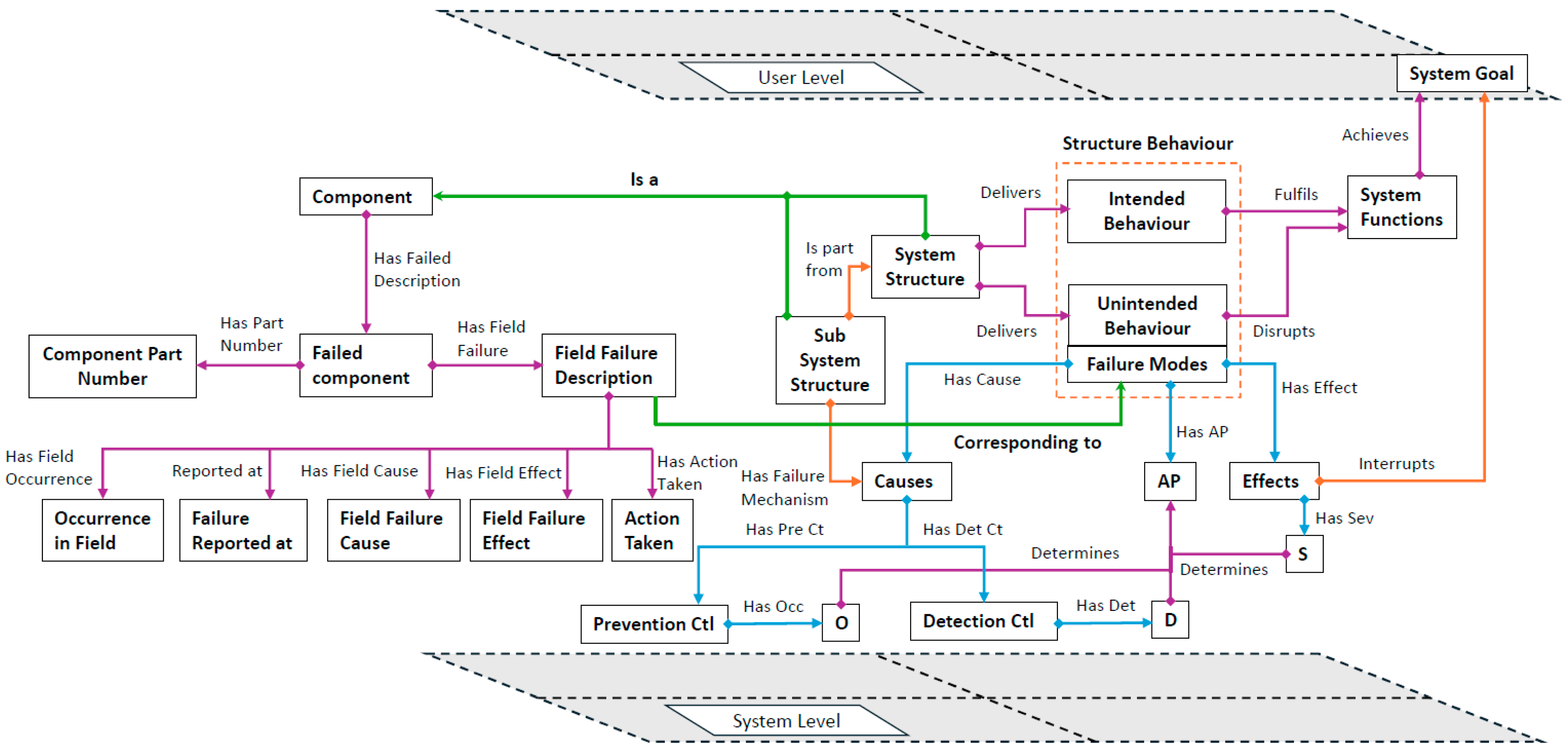
To link this reasoning with risk analysis, Younus et al. [29] introduced the Function–Behaviour–Structure–Failure Modes (FBSFM) framework, extending FBS by embedding failure modes, causes, and effects into function and behaviour representations. The FBSFM framework facilitates the representation as a knowledge graph, as illustrated in Figure 2, which enhances traceability between design intent and associated risks, particularly in early design phases when failure data are limited but critical.
The FBSFM framework’s strength lies in integrating heterogeneous design data, including functions, structures, behaviours, and early risk indicators, into a semantically structured format supporting reuse and collaboration. However, as it focuses primarily on early design data, it does not yet incorporate downstream lifecycle data such as warranty claims, operational failures, or field feedback, limiting its applicability for lifecycle risk management.
The new framework, henceforth referred to as the Integrated System Ontology (ISOnto), extends FBSFM to include the consideration of field return data. While FBSFM is effective in capturing functional requirements, expected behaviours, structural elements, and failure analysis, it falls short in incorporating operational realities, particularly under faulty or failed conditions. Conventional FBSFM primarily focuses on conceptual-level modelling and often overlooks the feedback generated during real-world operations including unanticipated failures and performance deviations.
The ISOnto framework addresses this limitation by incorporating a dedicated field feedback ontology and establishing explicit semantic links between the entities of the design phase (FBSFM layer) and those of the field failure layer (return field data). The integration hinges on analysing the structure of field data to describe failures, while the FBSFM layer relies on function–behaviour–structure analysis. The structure, as the physical representation in both domains, acts as a semantic bridge between the two layers. By formally mapping the structure and recorded failure characteristics in an ontological framework and linking these characteristics to design entities, the ISOnto framework presents a more comprehensive and realistic model. Thus, it goes beyond the traditional “as-designed” perspective to encompass the “as-is” or “as-failed” realities, offering a richer foundation for design synthesis, reliability analysis, and risk management within a unified ontological structure.
The proposed ontological framework delivers four key contributions to enhance failure analysis and design knowledge integration. First, it establishes a unified semantic repository that consolidates system design data, including functions, behaviours, structures, and failure modes, with field return data such as observed failures, causes, and effects. This integrated structure enables automated retrieval and the reuse of engineering knowledge, significantly reducing the effort required to access validated design and risk information. Furthermore, the framework supports early stage failure analysis by explicitly linking design-phase entities to operational failure characteristics through semantic representations. This connection strengthens the accuracy of risk identification before physical implementation. Finally, the ontology facilitates more informed decision-making by supporting semantic querying and rule-based reasoning, allowing for proactive risk mitigation and minimising the likelihood of late-stage design modifications.
The overall methodology for developing the ISOnto framework is illustrated in Figure 3, which provides a roadmap of the sequential development stages. This roadmap is divided into three main phases: (1) ontology construction, involving the parallel development of the FBSFM and field data ontologies from their respective knowledge sources; (2) ISOnto framework development, where formal mappings are established to merge the two ontologies by connecting system design elements with field failure mode components; (3) knowledge representation, in which the integrated ontology is deployed into a knowledge repository, supporting structured querying and encompassing technical, domain-specific, and practical validation.
This central ISOnto consolidates entities from both the system design phase (function–behaviour–structure and FMEA failure modes) and the field return phase (field failure characteristics), forming a coherent semantic representation. The roadmap emphasises the structured flow of knowledge from distinct sources into a consolidated framework, resulting in a system ready for advanced knowledge management, cross-domain analysis, and decision support.

3.2. Ontological Framework Development

This methodology develops a field feedback ontology by adapting the “Localising Ontologies” scenario from the NeOn Methodology to suit engineering contexts, specifically focusing on warranty claim data. A warranty represents a contractual obligation where manufacturers commit to addressing product failures occurring within a defined period. A warranty claim is filed when a customer exercises this right in response to a product malfunction [72].
Previous studies have demonstrated the critical value of warranty claim data for understanding real-world product failures [73]. The proposed framework introduces a warranty claims ontology that can be integrated with previously developed ontologies to create a unified knowledge base encompassing both design-phase and use-phase information. This ontology facilitates the reuse and sharing of knowledge from both the design and use phases of a system by providing machine- and human-readable representations of field data.
Warranty claims typically contain technician and customer narratives, often linked to specific components that have been repaired or replaced. However, the structure and terminology vary significantly due to differences in technician expertise, customer articulation, language, and organisational standards. Field feedback data may originate from various sources such as warranty databases, phone logs, surveys, and safety complaint records [18]. This heterogeneity complicates the manual interpretation and integration of terminology, but the embedded data remain essential for identifying failure patterns and verifying design assumptions [74].
The common practice in the automotive industry, as observed in field feedback checklists from manufacturers, reveals that, although formats differ, key elements are often present: dealership details, mileage, component identifiers, technician verbatim, part numbers, and validation comments. These variations highlight the lack of a universal structure, resulting in inconsistent and unstructured data across the industry.
The proposed ontology focuses on component identification as the structural anchor for representing and analysing warranty data. Components are linked to detailed part descriptions and manufacturer-issued part numbers, which contain metadata such as production location and specifications. This supports granular traceability throughout the product lifecycle. By recognising the diversity in claim formats, the ontology provides a flexible but consistent model grounded in shared references like part number and component type.
As illustrated in Table 3, adapted from [58], structured warranty data entries include vehicle serial number, labour code, repair type, vehicle age at failure, mileage, cost of repair, and technician feedback. These entries enable the systematic analysis of failure patterns, for example, repeated headlamp failures with descriptions like “bulb blown” or “filament burnt”, and support ontology development focused on repair actions and real-world effects.
The specific ontology developed in this study aligns with the internal warranty claim structure used by a global automotive manufacturer, selected for its detailed technical content and consistent field data input. This industrial data format includes technician and customer narratives, cross-references to FMEA entries, inspection outcomes, and recorded decisions such as approvals, rework requests, or rejections. Such structured documentation enhances traceability and data confidence. Table 4 presents a representative structure from the industry dataset, illustrating key elements such as component details, part numbers, failure modes, effects, causes, and field occurrence rates.
Despite structural differences across organisations, the common denominator in all field claims is the structural anchoring of the failure to a specific component. Whether in headlamps, lenses, or PCBAs, claims consistently refer to the affected part, around which additional data descriptions, diagnoses, and repair actions are organised. This observation informs the structure of the field feedback ontology, which captures these relationships in a coherent semantic model.
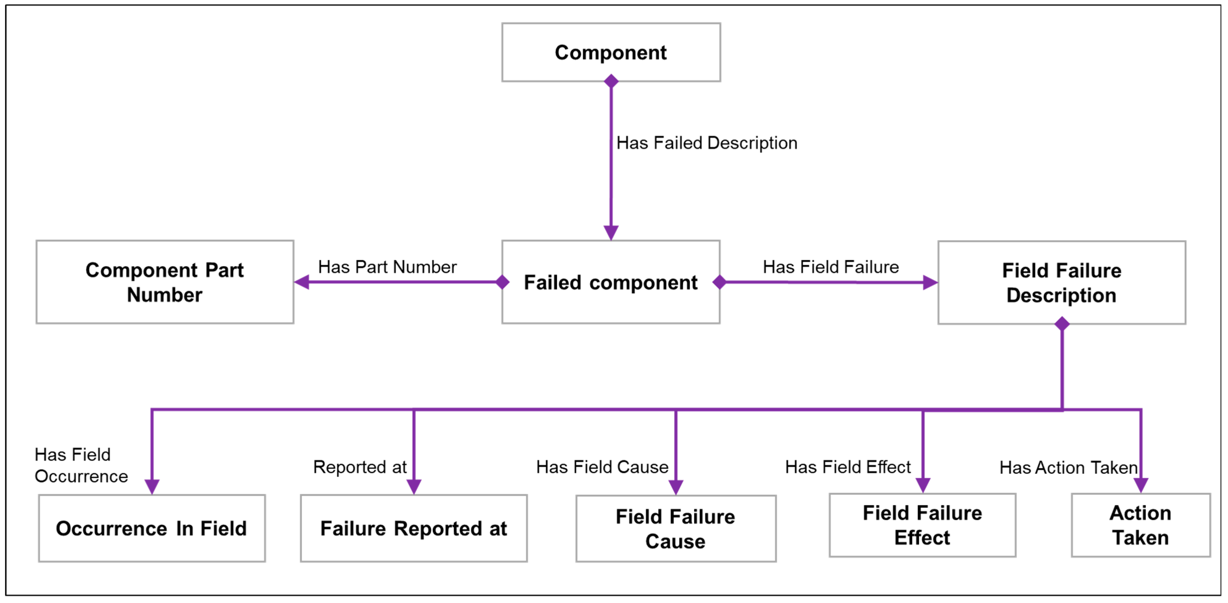
The ontology begins with identifying the reported component. While customers may refer to the part in non-technical language, technicians diagnose the specific failed component using precise terminology. This distinction is formally captured as:
  • Component “Has Failed Description” → Component Failed;
  • Failed Component Component;
  • Component failed = {pn1,pn2,…,pn7}, where pncomponent failed.
Each failed component is associated with one or more observed failure modes during inspection, modelled as:
  • Failed Component “Has Field Failure” → {FM1,FM2,…,FMₙ}, where FM Field Failure Modes.
Field failure instances are enriched with additional attributes:
  • Field Failure Description = {Effect, Cause, Action Taken, Reported At, Occurence}
    where:
    • Effect ∈ {Customer Verbatim, Technician Verbatim};
    • Cause ∈ {Technician Diagnosis, Manufacturer Analysis};
    • Action Taken ∈ {Technician Action, Manufacturer Action};
    • Reported At ∈ {Mileage or Age at failure};
    • Occurrence ∈  N (Natural Numbers).
This model allows for both qualitative insights (technician/customer narratives) and quantitative analysis (failure frequency, cost, mileage). Mileage or operational time at the point of failure is captured as:
  • Mileage → Age (t) at time of failure.
The complete semantic model is visualised in Figure 4, which presents the knowledge graph of the field feedback ontology. This ontology transforms raw claim records into a structured, machine-readable format that supports integration with the FBSFM ontology.
While the field feedback ontology is domain-specific, it was initially designed to reflect the data structure commonly employed by large automotive OEMs and built with extensibility in mind. Its core logic and relationships can be adapted to other formats and industry sectors. Unlike the abstract FBSFM ontology, this field-level ontology captures concrete, real-world failure knowledge and bridges the gap between use-phase feedback and design validation.

3.3. Integrated Systems Ontology ISOnto-Based Approach

The FBSFM ontology functions as a unified, high-level semantic model integrating key data from the design phase of a product’s lifecycle. It combines system modelling represented by the Function–Behaviour–Structure (FBS) ontology with risk assessment captured through design FMEA. This integration enables a comprehensive representation of design knowledge, supporting applications across various systems and domains due to its generality and modular structure.
In contrast, the field feedback ontology focuses on the use phase, is inherently domain-specific, and was developed from industry-specific warranty claim formats. It captures empirical data based on operational failures, typically analysed by technicians and warranty teams through structured inspection and repair activities. Despite its tailored structure, the ontology remains adaptable for different industrial contexts by accommodating variation in claim formats and vocabulary.
A key distinction between the two lies in failure identification. In FBSFM, failure modes are derived from design-level functional analysis, tracing faults to intended behaviours and functional requirements. In the field feedback ontology, failures emerge from structural analysis and direct observations. These complementary perspectives form the foundation for integration: design-time assumptions versus real-world manifestations.
This section presents the integration of the two ontologies into a unified ISOnto framework. ISOnto enables a semantic bridge between design-phase knowledge and use-phase data, providing a holistic foundation for lifecycle-based failure analysis. The unified model supports bidirectional traceability, linking field failures back to design intentions and validating design models with field feedback. This enhances decision-making related to risk mitigation, maintenance planning, and design evolution.
Figure 2 and Figure 4 (from earlier sections) reveal a conceptual intersection point between the two ontologies. Specifically, system structure or subsystem structure in the FBSFM ontology corresponds to the component entity in the field feedback ontology. This relationship is expressed as:
  • Component System Structure ∨ Subsystem Structure.
Field failure descriptions from the use phase can also be semantically aligned with FMEA entries. When a field failure matches a documented FMEA mode, it validates the design risk prediction:
  • Field Failure Description ≡ FMEA fm.
If the failure is absent from the FMEA, it is recognised as a new failure mode, providing valuable insight for updating design assumptions:
  • Field Failure Description ≢ FMEA ⇒ New Failure Mode.
Figure 5 illustrates the unified ISOnto framework, showing how entities and relationships from both ontologies are harmonised into a coherent semantic structure. This integration facilitates the ongoing validation of FMEA entries and enriches system knowledge by incorporating real-world failures into the design knowledge base.
The ISOnto knowledge graph also supports multilevel system decomposition, following the hierarchical capabilities of FBSFM. While field data often correspond to single-level component failures, these can be mapped across different system levels depending on how failures are reported. This flexibility ensures that ISOnto can accommodate hierarchical modelling, even when the field data are initially flat or semi-structured.
The culmination of this methodology is the integration of the FBSFM and field feedback ontologies into a unified systems framework known as the ISOnto. This integrated ontology establishes two-way traceability: design-phase assumptions can be aligned with real-world observations, while operational failures can inform and refine system understanding. Central to this integration is the semantic “is-a” relationship that connects system structures from the FBSFM ontology with components identified in the field.
Field failure descriptions are either semantically mapped to existing system knowledge or introduced as new insights, enriching the conceptual representation of failure across the lifecycle. The term ISOnto reflects the convergence of ontological models from distinct lifecycle stages. It unifies system modelling and failure analysis from the design phase with empirical field feedback derived from warranty claims and technical inspections.
By semantically linking these heterogeneous sources, ISOnto enables cross-domain knowledge reuse, supports lifecycle traceability, and strengthens data-driven decision-making across engineering functions. The unified ontology provides a scalable, adaptive, and traceable foundation for failure analysis, bridging theoretical design models with empirical operational data and paves the way for continuous improvement and intelligent reasoning within complex systems engineering.

4. Implementation

4.1. ISOnto Ontology Development and Tools

This section outlines the implementation of the ISOnto, which combines the design-phase FBSFM ontology with the field feedback ontology into a unified semantic model. The development process focuses on the integration methodology, supporting tools, and knowledge representation techniques used to construct and validate the ISOnto.

4.1.1. Methodology for Integrating Design and Field Knowledge

The ISOnto was developed by semantically integrating system design knowledge (FBSFM) with field returned knowledge derived from “warranty claims”. This dual-layer integration ensures that both the “as-designed” and “as-observed” system states are represented within a coherent ontological structure. A structured methodology was followed:
  • Design Layer structuring (FBSFM): Core classes were defined for Function, Expected Behaviour, Unintended Behaviour, Structure, and FMEA elements such as Failure Mode, Cause, and Effect. The Unintended Behaviour class was central to linking system deviations with failure manifestations.
  • Field layer structuring (feedback ontology): Classes were created for Component, Field Failure Mode, Effect, Cause, Action Taken, Occurrence, and Part Number. This structure reflects real-world observations gathered from inspection and warranty reports.
  • Cross-ontology mapping: Semantic relationships were established between the two layers. For example:
    Component System Structure;
    Field Failure Description ≡ DFMEA Failure Mode (if matched);
    Field Failure DescriptionNew Failure Mode (if unmatched).
These mappings allow for lifecycle traceability and the enrichment of design models with empirical failure feedback. The integration captures how field-identified failures either validate or challenge existing design assumptions, enabling a more adaptive knowledge system.

4.1.2. Tools and Formalisation Approach

  • The ISOnto was developed using Protégé, an open-source ontology editor that supports OWL (Web Ontology Language). Protégé facilitated the creation of the dual-layer structure and the semantic mappings between the design and field elements:
    a.
    Definition of classes, relationships, and domain/range axioms for both ontologies.
    b.
    Use of the “Object Properties” tab to define lifecycle-spanning relations, such as “Field Failed Component Description”, “Has Field FailureMode Description”, and “Field FailureMode Description”.
    c.
    Logical validation using the HermiT reasoner ensured consistency across design and field entities and highlighted any semantic contradictions.
Manchester Syntax was adopted for expressing logical rules due to its readability, especially during expert validation. To complement this expert-driven validation, the ISOnto was also evaluated for structural soundness using the OOPS! (OntOlogy Pitfall Scanner) tool [64]. This automated service checks for common modelling pitfalls and semantic weaknesses in ontologies. The evaluation of ISOnto identified three minor issues, as shown in Figure 6: missing annotations (P08, 115 cases), undeclared inverse relationships (P13, 61 cases), and inconsistent naming conventions (P22, affecting the ontology as a whole). According to OOPS!, these are non-critical pitfalls that do not affect logical consistency or reasoning functionality. Addressing them would mainly improve the documentation quality and refinement. Thus, the structural validation confirmed that the ontology is logically consistent and fit for reasoning tasks.

4.1.3. Knowledge Graph Representation

To enhance comprehension and support stakeholder communication, the ISOnto was visualised as a knowledge graph using OWLGrEd. This graphical view represents semantic linkages between lifecycle knowledge components and supports intuitive exploration of design-to-field relationships. As shown in Figure 7, key classes and properties are visualised including:
  • Function, Behaviour, Structure, Failure Mode (design layer);
  • Component, Field Failure Mode, Cause, Effect, Action Taken (field layer);
  • Semantic bridges such as “Field Failure Mode corresponds to FMEA Failure Mode” or “Component instance of System Structure”.
This knowledge graph helps demonstrate how operational data are integrated with system design knowledge, supporting advanced reasoning, lifecycle traceability, and decision support.
The next section presents a case study from the automotive industry to demonstrate the application of the ISOnto framework in a real-world engineering context, showcasing its ability to represent, connect, and leverage cross-phase data for improved reliability engineering.

4.2. Case Study Implementation

The proposed framework was validated using an industrial case study of a headlamp system provided by a partner company, one of the global automotive manufacturers. This real-world application demonstrates the feasibility of the proposed methodology for unifying design-phase knowledge with use-phase data. The implementation process follows five key steps, as illustrated in Figure 8.
  • Step 1: Preprocess and prepare the system model and FMEA data from the design phase.
  • Step 2: Deploy the pre-processed design data into the FBSFM layer of the ISOnto.
  • Step 3: Preprocess and prepare field data from the use phase.
  • Step 4: Deploy the field feedback data into the field ontology layer of the ISOnto.
  • Step 5: Save and explore the integrated ISOnto as a unified knowledge repository.

4.2.1. Case Study Analysis

The case study comprised two primary knowledge sources:
  • System modelling documentation: This included architectural diagrams and functional decomposition data. A structural breakdown of the headlamp system is shown in Figure 9 as a UML diagram, derived from internal system architecture documentation.
2.
FMEA Spreadsheets: Provided in Excel format, these contain:
  • A standard AIAG/VDA-style FMEA table;
  • A system architecture matrix mapping function and behaviours;
  • A list of focus element functions with their behavioural criteria.
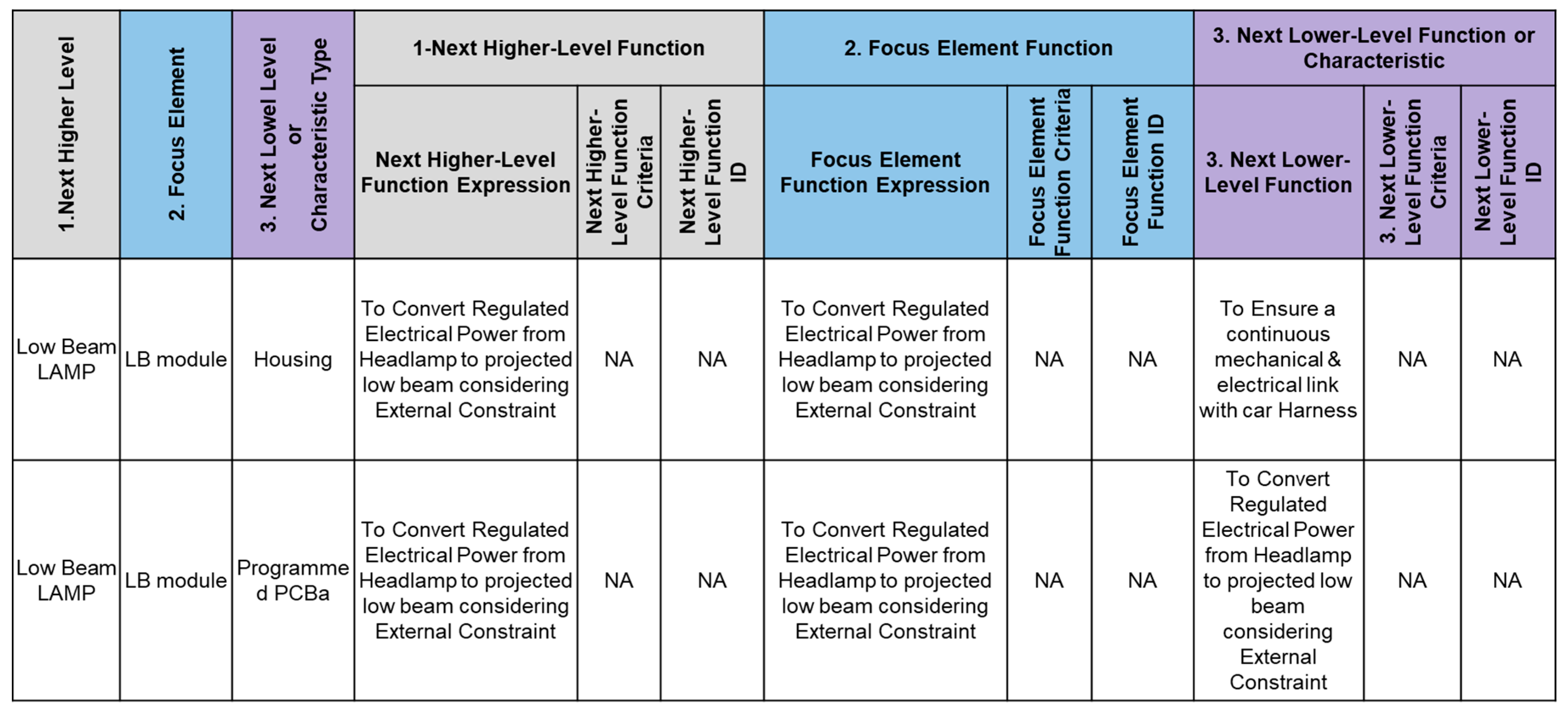
    • The system is hierarchically decomposed into three levels, as reflected in the FMEA snapshot shown in Figure 10:
      Level 1: Entire headlamp system (Low Beam Lamp);
      Level 2: Focus elements, e.g., LB Module;
      Level 3: Individual components, e.g., Housing.

4.2.2. Step 1—Text Preparation and Preprocessing

To prepare the case study data for ontology population in Protégé, a preprocessing step was implemented using a custom Python script using google colab. This addressed:
  • Space and special character formatting;
  • Replacement of missing or null values;
  • Harmonisation of terms to match ontology constraints.
    The preprocessing ensured semantic consistency between the Excel-based documentation and the OWL ontology structure.

4.2.3. Step 2—Data Population into the Ontology

After preprocessing the system model and FMEA data from the design phase (Step 1), the cleaned data were deployed into the FBSFM layer of the ISOnto. This step involved importing functional elements, behavioural descriptions, structural components, and associated failure modes and effects from Excel-based case study documents into Protégé.
Using Protégé’s “Create axioms from Excel sheet” feature, the following actions were performed:
  • Column mapping: Spreadsheet columns were mapped to ontology classes such as Function, Expected Behaviour, Unintended Behaviour, Structure, Failure Mode, Failure Cause, and Failure Effect.
  • Relation assignment: Semantic relationships were defined including links. These relationships established semantic coherence across the FBSFM layer, reflecting the functional decomposition and associated risk information of the system.
The populated design-phase knowledge was saved using Manchester Syntax, ensuring clarity and consistency for both human-readable editing and automated reasoning. The mapping logic and configurations were saved as JSON templates, allowing for reproducibility and scalability in future case study applications.

4.2.4. Step 3—Preprocess and Prepare Field Data from the Use Phase

This step focuses on preparing the field data collected during the use phase for integration into the field feedback layer of the ISOnto. The field data originated from structured warranty claim records and inspection reports provided by the industrial partner. These included technician verbatim, component identifiers, failure modes, effects, causes, part numbers, and operational metadata such as mileage at failure and frequency of occurrence.
To ensure compatibility with the ontology, a custom Python script was developed for data preprocessing. This process included:
  • Text cleaning: Removing special characters and standardising inconsistent terminology;
  • Entity normalisation: Converting natural language expressions into controlled vocabulary terms aligned with the ontology’s class labels;
  • Structural parsing: Extracting key fields (e.g., Component, Failure Mode, Cause, Effect, Action Taken) and organising them into tabular form suitable for Protégé ingestion;
  • Missing data handling: Identifying and managing incomplete or null values to prevent semantic errors during population.
The preprocessing ensured that the field data adhered to the syntactic and semantic requirements of the ontology framework. By converting raw warranty claim entries into structured and standardised representations, this step establishes a reliable foundation for semantic deployment into the ISOnto.

4.2.5. Step 4—Deploy Field Feedback into the ISOnto Ontology

Following the population of design-phase data into the FBSFM layer, the next stage involves integrating field data from the use phase. After preprocessing (Step 3), the cleaned and structured field feedback comprising components, failure modes, causes, effects, and associated metadata was deployed into the field ontology layer of the ISOnto framework.
This was performed in Protégé by importing structured Excel templates into corresponding ontology classes. Semantic relationships were established between the populated field entities and their design-phase counterparts. For instance:
  • Component instances were linked to System Structure via “is-a” relationships;
  • Field Failure Mode entities were mapped to DFMEA Failure Modes where applicable.
This deployment created a connected knowledge base, facilitating traceability between the field feedback and system design structures. Mapping rules and relationship definitions were again saved in reusable JSON configurations to support consistency across future deployments.

4.2.6. Step 5—Save and Explore the ISOnto Ontology as a Knowledge Repository

Upon completing the integration of both design and field data, the ISOnto was saved in Manchester Syntax format, enabling semantic querying and further reasoning. A custom Python script was then used to process and enhance the repository for exploration. The script performed two main tasks:
  • Replaced underscores in entity labels to improve readability;
  • Removed lengthy URI paths to simplify visual outputs and query responses.
To maintain confidentiality, anonymised examples are presented to illustrate the ontology’s exploration capabilities. Using the Python-based interface, users can enter a search term such as a function, failure mode, or component and retrieve all related knowledge including hierarchical relations and linked failure data.
The output interface applies colour coding for ease of interpretation:
  • Green: Ontology class, types, and facts;
  • Grey: Object properties and semantic relations;
  • Yellow: Case-specific data from the design and use phase.
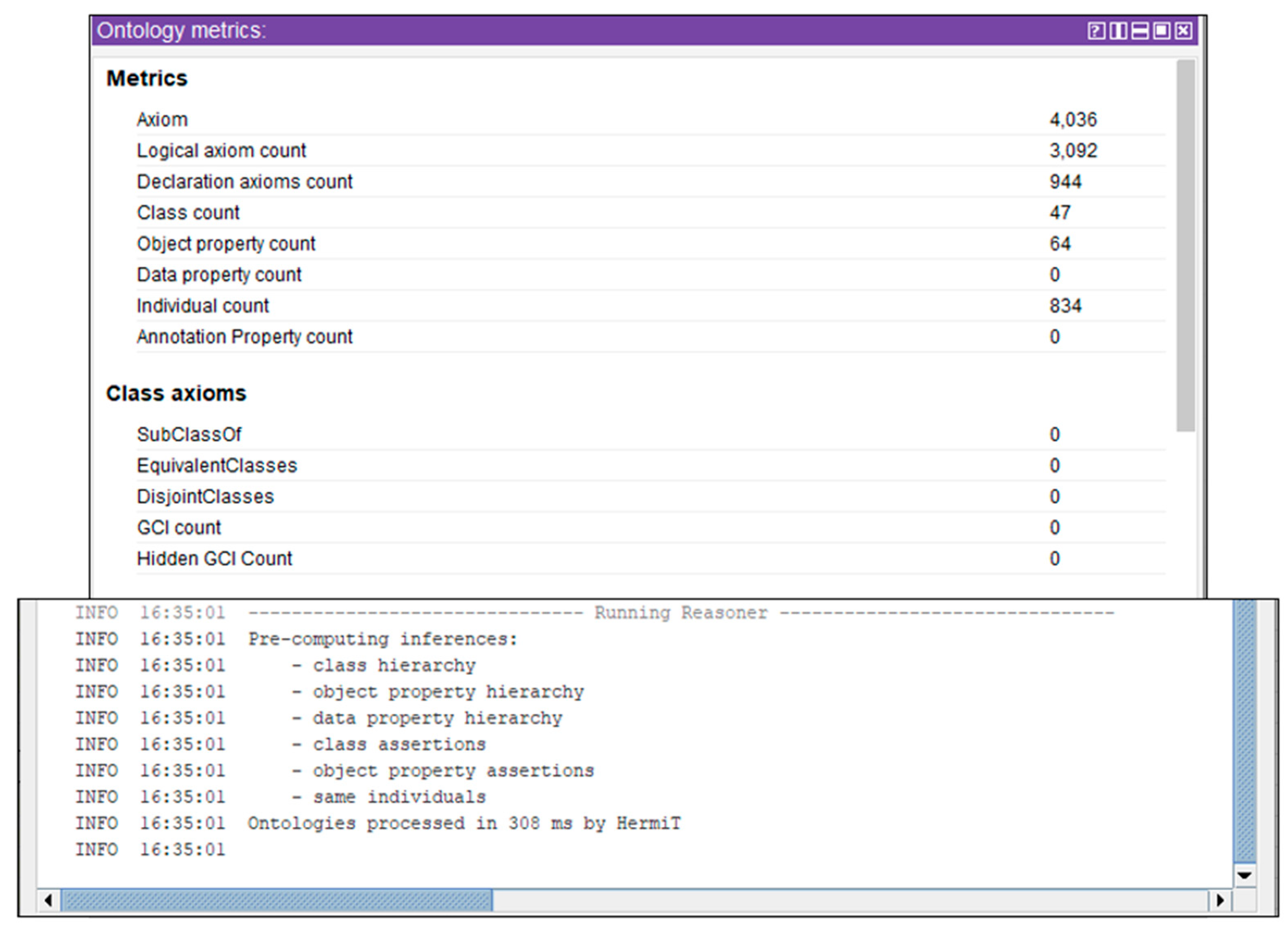
These outputs demonstrate how the ISOnto functions as a lifecycle knowledge repository, enabling structured exploration, failure traceability, and system-level diagnostics. This final stage confirms the ontology’s usability for engineering decision support and its potential for ongoing knowledge enrichment in future system iterations. In addition to qualitative exploration, quantitative ontology metrics were assessed to validate the robustness of the ISOnto framework. Following the integration of the design-phase case study data into the FBSFM layer, the ontology comprised 37 classes, 53 object properties, and 524 individual instances, consistent with the three-level decomposition of the headlamp system. The dataset was successfully imported into Protégé without errors, confirming semantic alignment with the ontology schema. Logical reasoning using the HermiT reasoner completed all inferences in 127 milliseconds, validating the absence of semantic contradictions.
After populating with the field feedback ontology, the ISOnto framework expanded to 47 classes, 64 object properties, and 834 individuals, collectively generating over 4000 axioms, as shown in Figure 11. The reasoning process was again completed successfully in 308 milliseconds, confirming semantic integrity and logical consistency after incorporating real-world failure data. These metrics provide quantitative evidence of ISOnto’s scalability and readiness for advanced querying and reasoning tasks.

4.2.7. Ontology Exploration—Example 1: LED Colour Bin Mismatch

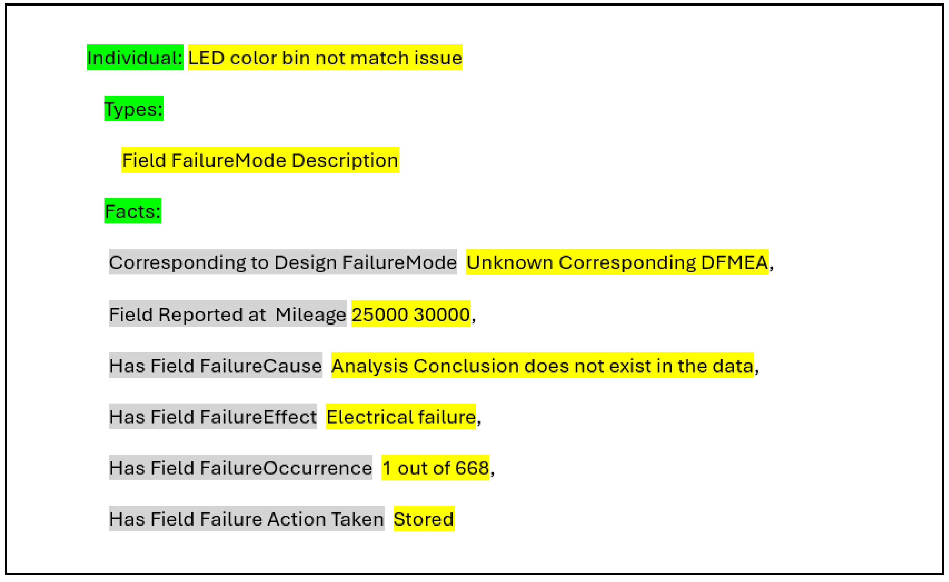
The first example demonstrates a case of a real-world field failure captured within the populated ISOnto. As shown in Figure 12, the failure instance was labelled:
  • Individual: LED colour bin not match issue;
  • Type: Field FailureMode Description.
The ontology instance illustrates a real-world failure event captured from field data. It highlights a scenario where no corresponding DFMEA entry exists, suggesting a gap in the original design risk assessment. The failure was reported at a mileage of 25,000–30,000 km and classified as an electrical fault. Due to the absence of a documented root cause analysis, the incident remained unresolved and was simply recorded without corrective action. With only one occurrence out of 668 units, it exemplifies how rare but unanticipated failures can be semantically captured and preserved for future analysis and potential design feedback.
This example demonstrates a failure mode observed in the field that lacks a corresponding entry in the existing FMEA. It highlights how the ISOnto framework detects unanticipated issues, enabling traceability and field feedback into future design revisions. The failure is classified under electrical faults and stored despite the lack of analytical resolution, showcasing the ontology’s capacity to document and preserve unclassified but impactful events.

4.2.8. Ontology Exploration—Example 2: Lens Breakage

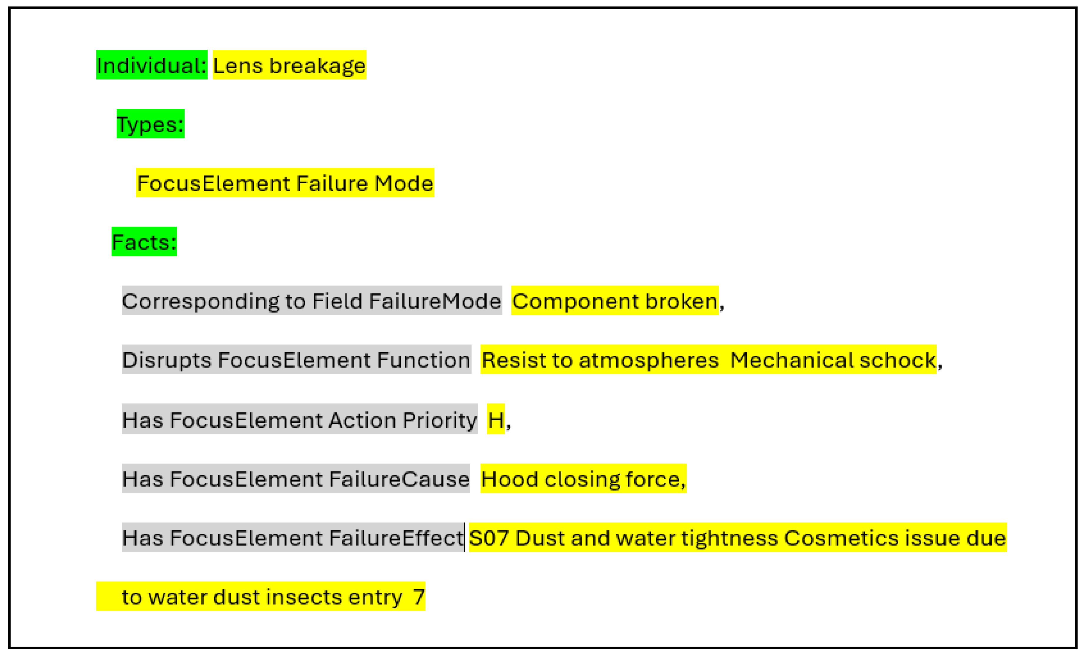
As shown in Figure 13, the second example illustrates a structured failure scenario in which a design-level failure mode, “lens breakage”, is semantically linked to its corresponding field failure: component breakage. This failure disrupts the function of resisting environmental stresses such as atmospheric conditions and mechanical shock. The ontology captures the root cause (hood closing force), assigns it a high action priority (H), and outlines the resulting effects including compromised sealing (S07 dust and water tightness) and cosmetic degradation from external contaminants like dust, water, and insects. This example demonstrates how the ontology enables traceability between operational symptoms and design intent.
This example demonstrates a field failure scenario, “lens breakage”, originating from mechanical stress due to hood closing force. The ISOnto framework enables semantic linkage between this observed failure and the disrupted functional expectation, namely environmental sealing and impact resistance. By mapping the field failure mode “component broken” to its corresponding FMEA entry, the ISOnto supports direct traceability between real-world issues and design-phase risk analysis. The recorded effects, such as dust and water ingress and cosmetic degradation, are explicitly connected to the functional failures defined in the FMEA. Additionally, the high action priority (H) assigned within the ontology enhances decision-making by flagging critical issues that require immediate design or process-level intervention.

5. Discussion

The motivation behind this research stems from the persistent challenge of bridging the semantic and lifecycle gap between system design models and real-world operational data. Traditional risk analysis methods, such as FMEA, are typically confined to the design phase and often fail to incorporate empirical field feedback. This separation results in fragmented knowledge and limited traceability between design assumptions and in-service failures.
To address this, the paper introduced the ISOnto, an integrated extension, dual-layer ontological framework that integrates the Function–Behaviour–Structure–Failure Mode (FBSFM) model with a field feedback ontology derived from warranty claims and technician reports. Unlike prior approaches that focus solely on aligning system models with FMEA data, this work extends the design-time representation to include operational failures, enabling lifecycle-based reasoning, validation, and adaptation.
The case study demonstrated the framework’s capacity to formalise and connect knowledge from both the design and use phases. By explicitly linking system structure entities with field-observed components and mapping field failure modes to FMEA entries, the ISOnto ontology supports two-way traceability between classes. It not only allows for real-world failures to be traced back to design-level constructs, but also reveals previously undocumented failure modes, enabling continuous improvement through semantic enrichment.
The validation was performed in an industrial environment with a real-world case study (of a headlamp system), with involvement from engineering experts. The dataset encompassed multiple knowledge layers including system-level architecture, DFMEA tables, and extensive warranty claim records. This diversity of data sources allowed for validation across different system levels (system, sub-system, and component). The structural ontology validation (via OOPS!) provides further evidence of ISOnto’s robustness. In addition, the quantitative ontology metrics comprising 47 classes, 64 object properties, 834 individuals, and more than 4000 axioms, with reasoning times consistently below half a second, provide further evidence of ISOnto’s scalability and its practical feasibility for querying and reasoning.
The decision to adopt an ontology-based approach, particularly through extending FBSFM, was driven by the need for formal semantics, lifecycle traceability, and machine reasoning. The FBSFM framework, developed in our earlier work, served as the conceptual foundation for this study. However, it primarily addressed early design reasoning and did not include mechanisms for integrating empirical field data or representing operational realities. ISOnto builds on this foundation by extending the scope of FBSFM to incorporate field feedback and lifecycle reasoning, thereby bridging the design–operation gap in dependability analysis.
Table 5 summarises the key distinctions between the earlier FBSFM framework and the extended ISOnto approach. This comparison reflects the evolution observed through the empirical application rather than theoretical generalisation. The table highlights ISOnto’s enhanced capacity for bidirectional traceability, semantic integration of field data, and lifecycle coverage, demonstrating its practical advantage in linking design intent to real-world performance outcomes.
These differences illustrate how ISOnto transforms the FBSFM foundation from a design-time reasoning model into a lifecycle-oriented framework capable of supporting automated validation and knowledge-driven decision-making. This positioning situates ISOnto as a natural evolution of earlier ontology-based representations rather than a competing framework, demonstrating its contribution to advancing dependability analysis across engineering domains.
While alternative approaches such as graph databases, relational mappings, or spreadsheet-based practices [75,76,77] can also store and manage FMEA or field data, they only provide limited support for automated reasoning and semantic traceability. Relational databases and spreadsheets are effective for tabular data management but do not natively support inference or ensure semantic consistency across heterogeneous sources. Graph databases improve relational querying and visualisation but still operate without the formal ontological axioms required for reasoning engines to detect inconsistencies or infer implicit relations. In contrast, the ontological approach adopted in ISOnto provides a machine-interpretable structure with explicit domain semantics, enabling both human understanding and automated reasoning, which are essential for validating FMEA assumptions against real-world failures. In parallel, tools like MBSE and graph databases offer some support for model integration; they often lack the explicit formalism needed to semantically align heterogeneous data from design and operation. The ISOnto framework fills this gap by establishing structured relationships, such as “Component ⊆ System Structure” and “Field Failure Mode ≡ DFMEA Mode”, supporting both consistency checking and advanced querying.
Beyond database and MBSE alternatives, it is also relevant to compare ISOnto with existing ontology frameworks. Formal or foundational ontologies have been widely advocated as a means to support abstraction and interoperability across domains (e.g., [78,79,80,81]). While these approaches provide strong theoretical grounding, they remain distant from the artefact-specific semantics found in DFMEA tables, warranty claims, and technician reports. In contrast, ISOnto deliberately adopts a domain-specific, artefact-driven methodology, designed to capture engineering semantics directly and support industrial decision-making. This strategy, validated through an industrial case study within the automotive sector, ensures immediate fidelity to engineering practice while still permitting future mapping to upper ontologies if broader cross-domain interoperability is required. ISOnto therefore complements rather than competes with formal frameworks, demonstrating how domain-grounded ontologies can provide actionable value in applied dependability engineering.
The integration methodology followed ontology engineering best practices, drawing on the NeOn methodology’s scenario for re-engineering and merging ontologies. The field ontology was designed around structural anchors in the data, particularly components and part numbers, which served as common reference points between design models and operational reports. This enabled a structured alignment between intended system functions and their actual failure manifestations in service.
From a technical implementation perspective, the use of Protégé and OWL formalisation, supported by Manchester Syntax, facilitated both human-readable inspection and machine-driven reasoning. The dual-layer ontology was populated using real-world data from a headlamp system provided by an automotive partner. Custom Python tools enabled preprocessing and knowledge extraction, while the ontology structure allowed users to navigate failure relationships across design hierarchies and field domains.
The case study not only validated the semantic expressiveness of the ISOnto framework but also illustrates its practical value. For instance, failure instances that lacked corresponding FMEA entries were captured and flagged as novel risks, while matched failures provided evidence to confirm design assumptions. The ontology’s capability to model cascading effects across functional and structural levels also supports future applications in failure propagation and reliability analysis.
While the ISOnto framework was validated through an industrial case study, the reliance on a single industrial case study appears as a limitation, in that the field feedback ontology was tailored to the specific structure and terminology of one manufacturer. However, the ontology design around structural anchors, such as components and part numbers, ensures adaptability to alternative formats including SAE J1739 and ISO 60812 standards [31] as well as warranty reporting systems used by other manufacturers. Furthermore, the framework is not restricted to the automotive sector; its architecture can be extended to domains such as aerospace, energy, or medical systems where lifecycle feedback and risk analysis are equally critical. Further industrial application examples with different products and database structures would provide further validation and enhance the generalisability of the framework.

6. Conclusions

This paper presented the development and validation of ISOnto, which extends and integrates the Function–Behaviour–Structure–Failure Modes (FBSFM) framework with field data, bridging the gap between system design knowledge and real-world field failure data across the product lifecycle. By semantically integrating the FBSFM model with a domain-specific field feedback ontology, ISOnto provides a unified representation that captures both design assumptions and operational realities. Using a real-world automotive case study developed in collaboration with engineers and domain experts, ISOnto demonstrated its ability to connect field-observed failures to system structures and FMEA models. This lifecycle-based semantic integration enabled two-way traceability, validating design assumptions against field performance and identifying unanticipated failures for future design refinement.
The framework supports machine-readable knowledge representation, semantic querying, and automated reasoning across the design and use phases. It provides more systematic failure analysis, enhances traceability, and establishes a foundation for decision support. For research, ISOnto shows how domain-specific ontologies can operationalise dependability analysis beyond conceptual models. For the industry, it demonstrates the practical benefits of lifecycle integration by strengthening DFMEA updating and creating reusable knowledge repositories.

Author Contributions

Conceptualisation, H.Y., F.C. and S.K.; Methodology, H.Y.; Software, H.Y.; Validation, H.Y., F.C., S.K., P.B. and D.D.; Formal analysis, H.Y.; Resources, F.C., P.B. and D.D.; Data curation, H.Y. and P.B.; Writing—original draft preparation, H.Y.; Writing—review and editing, F.C., S.K., P.B. and D.D.; Visualization, H.Y.; Supervision, F.C., S.K. and P.B.; Project administration, F.C. and S.K.; Funding acquisition, F.C., S.K., P.B. and D.D. All authors have read and agreed to the published version of the manuscript.

Funding

The authors acknowledge funding support for the research presented in this article through the France2030 OTPaaS project (Ref: Valeo: RM0233) funded by BPI-France.

Data Availability Statement

Data cannot be made available due to the commercially sensitive nature of the technical case study. Any enquiries regarding the data should be made to Pascal Bonnaud at pascal.bonnaud@valeo.com.

Conflicts of Interest

Authors Pascal Bonnaud and David Delaux are employed by the company Valeo. The remaining authors declare that the research was conducted in the absence of any commercial or financial relationships that could be construed as potential conflicts of interest.

References

  1. Theissler, A.; Pérez-Velázquez, J.; Kettelgerdes, M.; Elger, G. Predictive maintenance enabled by machine learning: Use cases and challenges in the automotive industry. Reliab. Eng. Syst. Saf. 2021, 215, 107864. [Google Scholar] [CrossRef]
  2. Kusiak, A. Smart manufacturing. Int. J. Prod. Res. 2018, 56, 508–517. [Google Scholar] [CrossRef]
  3. Chakraborty, S.; Jha, S.; Samii, S.; Mundhenk, P. Introduction to the special issue on automotive CPS safety & security: Part 1. ACM Trans. Cyber-Phys. Syst. 2023, 7, 1–6. [Google Scholar]
  4. Ebert, C.; Duarte, C.H. Digital Transformation. IEEE Softw. 2018, 35, 16–21. [Google Scholar] [CrossRef]
  5. Campean, F.; Neagu, D.; Doikin, A.; Soleimani, M.; Byrne, T.; Sherratt, A. Automotive IVHM: Towards Intelligent Personalised Systems Healthcare. In Proceedings of the Design Society: International Conference on Engineering Design, Delft, The Netherlands, 5–8 August 2019; Volume 1, pp. 857–866. [Google Scholar]
  6. AIAG-VDA. Failure Mode and Effects Analysis-FMEA Handbook: Design FMEA, Process FMEA, Supplemental FMEA for Monitoring et System Response; Automotive Industry Action Group: Southfield, MI, USA, 2019. [Google Scholar]
  7. Zhu, P.; Han, J.; Liu, L.; Lombardi, F. A stochastic approach for the analysis of dynamic fault trees with spare gates under probabilistic common cause failures. IEEE Trans. Reliab. 2015, 64, 878–892. [Google Scholar] [CrossRef]
  8. Liu, H.-C.; You, J.-X.; Li, P.; Su, Q. Failure mode and effect analysis under uncertainty: An integrated multiple criteria decision making approach. IEEE Trans. Reliab. 2016, 65, 1380–1392. [Google Scholar] [CrossRef]
  9. Huang, J.; Li, Z.S.; Liu, H.-C. New approach for failure mode and effect analysis using linguistic distribution assessments and TODIM method. Reliab. Eng. Syst. Saf. 2017, 167, 302–309. [Google Scholar] [CrossRef]
  10. Huang, J.; You, J.-X.; Liu, H.-C.; Song, M.-S. Failure mode and effect analysis improvement: A systematic literature review and future research agenda. Reliab. Eng. Syst. Saf. 2020, 199, 106885. [Google Scholar] [CrossRef]
  11. Korsunovs, A.; Doikin, A.; Campean, F.; Kabir, S.; Hernandez, E.; Taggart, D.; Parker, S.; Mills, G. Towards a Model-Based Systems Engineering Approach for Robotic Manufacturing Process Modelling with Automatic FMEA Generation. Proc. Des. Soc. 2022, 2, 1905–1914. [Google Scholar] [CrossRef]
  12. Parlatan, F.; Burgt, O.V.D. FMEA & FTA Integration in MBSE Approach for Healthcare Systems & Solutions. In Proceedings of the 2024 Annual Reliability and Maintainability Symposium (RAMS), Albuquerque, NM, USA, 22–25 January 2024; pp. 1–6. [Google Scholar]
  13. Winton, D.B.; Huang, Z.C. MBSE and FMEA Integration Using GENESYS. In Proceedings of the 2021 Annual Reliability and Maintainability Symposium (RAMS), Orlando, FL, USA, 24–27 May 2021; pp. 1–7. [Google Scholar]
  14. Huang, Z.; Hansen, R.; Huang, Z. Toward FMEA and MBSE integration. In Proceedings of the 2018 Annual Reliability and Maintainability Symposium (RAMS), Reno, NV, USA, 22–25 January 2018; pp. 1–7. [Google Scholar]
  15. Huang, Z.; Swalgen, S.; Davidz, H.; Murray, J. MBSE-assisted FMEA approach—Challenges and opportunities. In Proceedings of the 2017 Annual Reliability and Maintainability Symposium (RAMS), Orlando, FL, USA, 23–26 January 2017; pp. 1–8. [Google Scholar]
  16. Filz, M.-A.; Langner, J.E.B.; Herrmann, C.; Thiede, S. Data-driven failure mode and effect analysis (FMEA) to enhance maintenance planning. Comput. Ind. 2021, 129, 103451. [Google Scholar] [CrossRef]
  17. Yang, F.; Cao, N.; Young, L.; Howard, J.; Logan, W.; Arbuckle, T.; Sponseller, P.; Korssjoen, T.; Meyer, J.; Ford, E. Validating FMEA output against incident learning data: A study in stereotactic body radiation therapy. Med. Phys. 2015, 42, 2777–2785. [Google Scholar] [CrossRef]
  18. Rajpathak, D.; Xu, Y.; Gibbs, I. An integrated framework for automatic ontology learning from unstructured repair text data for effective fault detection and isolation in automotive domain. Comput. Ind. 2020, 123, 103338. [Google Scholar] [CrossRef]
  19. Qian, L.; Gero, J.S. Function–behavior–structure paths and their role in analogy-based design. AI EDAM 1996, 10, 289–312. [Google Scholar] [CrossRef]
  20. Gero, J.S.; Kannengiesser, U. A function–behavior–structure ontology of processes. AI EDAM 2007, 21, 379–391. [Google Scholar] [CrossRef]
  21. van Beek, T.J.; Erden, M.S.; Tomiyama, T. Modular design of mechatronic systems with function modeling. Mechatronics 2010, 20, 850–863. [Google Scholar] [CrossRef]
  22. Goel, A.K.; Rugaber, S.; Vattam, S. Structure, behavior, and function of complex systems: The structure, behavior, and function modeling language. AI EDAM 2009, 23, 23–35. [Google Scholar] [CrossRef]
  23. Hezla, L.; Gurina, R.; Hezla, M.; Rezaeian, N.; Nohurov, M.; Aouati, S. The Role of Artificial Intelligence in Improving Failure Mode and Effects Analysis (FMEA) Efficiency in Construction Safety Management. In Artificial Intelligence and Virtual Reality: Proceedings of 7th International Conference on Artificial Intelligence and Virtual Reality (AIVR 2023), Kumamoto, Japan, 21–23 July 2023; Springer: Singapore, 2023; pp. 397–411. [Google Scholar]
  24. Grabill, N.; Wang, S.; Olayinka, H.A.; De Alwis, T.P.; Khalil, Y.F.; Zou, J. AI-augmented failure modes, effects, and criticality analysis (AI-FMECA) for industrial applications. Reliab. Eng. Syst. Saf. 2024, 250, 110308. [Google Scholar] [CrossRef]
  25. Chari, S.; Seneviratne, O.; Gruen, D.M.; Foreman, M.A.; Das, A.K.; Mcguinness, D.L. Explanation Ontology: A Model of Explanations for User-Centered AI; Springer International Publishing: Cham, Swizerland, 2020; pp. 228–243. [Google Scholar]
  26. Ebrahimipour, V.; Rezaie, K.; Shokravi, S. An ontology approach to support FMEA studies. Expert Syst. Appl. 2010, 37, 671–677. [Google Scholar] [CrossRef]
  27. Ebrahimipour, V. Lexical Semantic Analysis to support Ontology Maintenance Modeling of FMEA. In Proceedings of the 2021 IEEE International Conference on Industrial Engineering and Engineering Management (IEEM), Mauritius, Mauritius, 7–8 October 2021; pp. 377–382. [Google Scholar]
  28. Rehman, Z.; Kifor, C.V. An ontology to support semantic management of FMEA knowledge. Int. J. Comput. Commun. Control 2016, 11, 507–521. [Google Scholar] [CrossRef]
  29. Younus, H.; Doikin, A.; Campean, F.; Kabir, S.; Abdullatif, A.; Delaux, D.; Bonnaud, P. An Extended Function-Behaviour-Structure Ontology to support FMEA within a System Engineering Context. Procedia CIRP 2024, 128, 644–649. [Google Scholar] [CrossRef]
  30. Wu, Z.; Liu, W.; Nie, W. Literature review and prospect of the development and application of FMEA in manufacturing industry. Int. J. Adv. Manuf. Technol. 2021, 112, 1409–1436. [Google Scholar] [CrossRef]
  31. SAE-J1739; Potential Failure Mode and Effects Analysis (FMEA) Including Design FMEA, Supplemental FMEA-MSR, and Process FMEA. SAE: Warrendale, PA, USA, 2009.
  32. IEC 60812; Failure Modes and Effects Analysis (FMEA and FMECA). IEC: Geneva, Switzerland, 2018.
  33. Baklouti, A.; Nguyen, N.; Mhenni, F.; Choley, J.-Y.; Mlika, A. Improved safety analysis integration in a systems engineering approach. Appl. Sci. 2019, 9, 1246. [Google Scholar] [CrossRef]
  34. Campean, I.F.; Henshall, E.; Rutter, B. Systems engineering excellence through design: An integrated approach based on failure mode avoidance. SAE Int. J. Mater. Manuf. 2013, 6, 389–401. [Google Scholar] [CrossRef]
  35. Henshall, E.; Campean, I.F.; Rutter, B. A Systems Approach to the Development and Use of FMEA in Complex Automotive Applications. SAE Int. J. Mater. Manuf. 2014, 7, 280–290. [Google Scholar] [CrossRef]
  36. Hecht, M.; Dimpfl, E.; Pinchak, J. Automated generation of failure modes and effects analysis from SysML models. In Proceedings of the 2014 IEEE International Symposium on Software Reliability Engineering Workshops, Naples, Italy, 3–6 November 2014; pp. 62–65. [Google Scholar]
  37. Girard, G.; Baeriswyl, I.; Hendriks, J.J.; Scherwey, R.; Müller, C.; Hönig, P.; Lunde, R. Model based safety analysis using SysML with automatic generation of FTA and FMEA artifacts. In Proceedings of the 30th European Safety and Reliability Conference and the 15th Probabilistic Safety Assessment and Management Conference (Esrel 2020 PSAM 15), Venice, Italy, 1–5 November 2020. [Google Scholar]
  38. Day, J.; Donahue, K.; Ingham, M.; Kadesch, A.; Kennedy, A.; Post, E. Modeling Off-Nominal Behavior in SysML; Infotech@ Aerospace: Houston, TX, USA, 2012; pp. 1–10. [Google Scholar]
  39. Campean, F. Systems Engineering Design through Failure Mode Avoidance-an Automotive Industry Perspective. In Proceedings of the 1st International Conference in Through Life Engineering Services, Shrivenham, UK, 5–6 November 2012. [Google Scholar]
  40. Sierla, S.; Tumer, I.; Papakonstantinou, N.; Koskinen, K.; Jensen, D. Early integration of safety to the mechatronic system design process by the functional failure identification and propagation framework. Mechatronics 2012, 22, 137–151. [Google Scholar] [CrossRef]
  41. Mansoor, A.; Diao, X.; Smidts, C. A method for backward failure propagation in conceptual system design. Nucl. Sci. Eng. 2023, 197, 2751–2777. [Google Scholar] [CrossRef]
  42. Russomanno, D.J.; Bonnell, R.D.; Bowles, J.B. Functional reasoning in a failure modes and effects analysis (FMEA) expert system. In Proceedings of the Annual Reliability and Maintainability Symposium 1993 Proceedings, Atlanta, GA, USA, 26–28 January 1993; pp. 339–347. [Google Scholar]
  43. Tumer, I.Y.; Stone, R.B. Mapping function to failure mode during component development. Res. Eng. Des. 2003, 14, 25–33. [Google Scholar] [CrossRef]
  44. Stone, R.B.; Tumer, I.Y.; van Wie, M. The function-failure design method. ASME. J. Mech. Des. 2005, 127, 397–407. [Google Scholar] [CrossRef]
  45. Jiménez López, E.; Cuenca Jiménez, F.; Luna Sandoval, G.; Ochoa Estrella, F.J.; Maciel Monteón, M.A.; Muñoz, F.; Limón Leyva, P.A. Technical Considerations for the Conformation of Specific Competences in Mechatronic Engineers in the Context of Industry 4.0 and 5.0. Processes 2022, 10, 1445. [Google Scholar] [CrossRef]
  46. Spreafico, C.; Russo, D.; Rizzi, C. A state-of-the-art review of FMEA/FMECA including patents. Comput. Sci. Rev. 2017, 25, 19–28. [Google Scholar] [CrossRef]
  47. El Hassani, I.; Masrour, T.; Kourouma, N.; Motte, D.; Tavčar, J. Integrating large language models for improved failure mode and effects analysis (FMEA): A framework and case study. Proc. Des. Soc. 2024, 4, 2019–2028. [Google Scholar] [CrossRef]
  48. Amrutha, H.; Ajinkya, J.; Surabhi, M. Application of failure modes and effects analysis (FMEA) in automated spot welding process of an automobile industry: A case study. J. Eng. Educ. Transform. 2021, 34, 281–289. [Google Scholar] [CrossRef]
  49. Jomthanachai, S.; Wong, W.P.; Lim, C.P. An Application of Data Envelopment Analysis and Machine Learning Approach to Risk Management. IEEE Access 2021, 9, 85978–85994. [Google Scholar] [CrossRef]
  50. Sader, S.; Husti, I.; Daróczi, M. Enhancing failure mode and effects analysis using auto machine learning: A case study of the agricultural machinery industry. Processes 2020, 8, 224. [Google Scholar] [CrossRef]
  51. Gheraibia, Y.; Kabir, S.; Aslansefat, K.; Sorokos, I.; Papadopoulos, Y. Safety+ AI: A novel approach to update safety models using artificial intelligence. IEEE Access 2019, 7, 135855–135869. [Google Scholar] [CrossRef]
  52. Brahim, I.B.; Addouche, S.-A.; El Mhamedi, A.; Boujelbene, Y. Build a Bayesian network from FMECA in the production of automotive parts: Diagnosis and prediction. IFAC-Pap. 2019, 52, 2572–2577. [Google Scholar] [CrossRef]
  53. Wang, H.; Zhao, Z.; Dai, Z.; Peng, Z.; Li, S. Using data mining and root cause analysis method for failure analysis in electronic components. IOP Conf. Ser. Mater. Sci. Eng. 2021, 1043, 022024. [Google Scholar] [CrossRef]
  54. Karim, R.; Suzuki, K. Analysis of warranty claim data: A literature review. Int. J. Qual. Reliab. Manag. 2005, 22, 667–686. [Google Scholar] [CrossRef]
  55. Hines, J.W.; Seibert, R. Technical Review of On-Line Monitoring Techniques for Performance Assessment. Volume 1. State-of-the-Art; United States Nuclear Regulatory Commission: Washington DC, USA, 2006. [Google Scholar]
  56. Prytz, R.; Nowaczyk, S.; Rögnvaldsson, T.; Byttner, S. Predicting the need for vehicle compressor repairs using maintenance records and logged vehicle data. Eng. Appl. Artif. Intell. 2015, 41, 139–150. [Google Scholar] [CrossRef]
  57. Khoshkangini, R.; Pashami, S.; Nowaczyk, S. Warranty claim rate prediction using logged vehicle data. In Progress in Artificial Intelligence: 19th EPIA Conference on Artificial Intelligence, EPIA 2019, Vila Real, Portugal, 3–6 September 2019; Proceedings, Part I 19; Springer: Cham, Switzerland, 2019; pp. 663–674. [Google Scholar]
  58. Rajpathak, D.; De, S. A data-and ontology-driven text mining-based construction of reliability model to analyze and predict component failures. Knowl. Inf. Syst. 2016, 46, 87–113. [Google Scholar] [CrossRef]
  59. Lu, J.; Ma, J.; Zheng, X.; Wang, G.; Li, H.; Kiritsis, D. Design ontology supporting model-based systems engineering formalisms. IEEE Syst. J. 2021, 16, 5465–5476. [Google Scholar] [CrossRef]
  60. Chen, J.; Chen, Y.; Hu, Z.; Lu, J.; Zheng, X.; Zhang, H.; Kiritsis, D. A semantic ontology-based approach to support model-based systems engineering design for an aircraft prognostic health management system. Front. Manuf. Technol. 2022, 2, 886518. [Google Scholar] [CrossRef]
  61. Hodkiewicz, M.; Klüwer, J.W.; Woods, C.; Smoker, T.; Low, E. An ontology for reasoning over engineering textual data stored in FMEA spreadsheet tables. Comput. Ind. 2021, 131, 103496. [Google Scholar] [CrossRef]
  62. Booshehri, M.; Emele, L.; Flügel, S.; Förster, H.; Frey, J.; Frey, U.; Glauer, M.; Hastings, J.; Hofmann, C.; Hoyer-Klick, C. Introducing the Open Energy Ontology: Enhancing data interpretation and interfacing in energy systems analysis. Energy AI 2021, 5, 100074. [Google Scholar] [CrossRef]
  63. Suárez-Figueroa, M.C.; Gómez-Pérez, A.; Fernández-López, M. The NeOn methodology for ontology engineering. In Ontology Engineering in a Networked World; Springer: Berlin/Heidelberg, Germany, 2011. [Google Scholar]
  64. Poveda-Villalón, M.; Fernández-Izquierdo, A.; Fernández-López, M.; García-Castro, R. LOT: An industrial oriented ontology engineering framework. Eng. Appl. Artif. Intell. 2022, 111, 104755. [Google Scholar] [CrossRef]
  65. Pinto, H.S.; Staab, S.; Tempich, C. DILIGENT: Towards a fine-grained methodology for DIstributed, Loosely-controlled and evolvInG Engineering of oNTologies. In Proceedings of the 16th Eureopean Conference on Artificial Intelligence, ECAI’2004, including Prestigious Applicants of Intelligent Systems, PAIS 2004, Valencia, Spain, 22–27 August 2004; p. 393. [Google Scholar]
  66. Hamraz, B.; Caldwell, N.H.; Ridgman, T.W.; Clarkson, P.J. FBS Linkage ontology and technique to support engineering change management. Res. Eng. Des. 2015, 26, 3–35. [Google Scholar] [CrossRef]
  67. Eisenbart, B.; Gericke, K. Function in Engineering. In The Routledge Handbook of the Philosophy of Engineering; Routledge: Abingdon, UK, 2020. [Google Scholar]
  68. Gero, J.S. Design prototypes: A knowledge representation schema for design. AI Mag. 1990, 11, 26. [Google Scholar]
  69. Umeda, Y.; Ishii, M.; Yoshioka, M.; Shimomura, Y.; Tomiyama, T. Supporting conceptual design based on the function-behavior-state modeler. Artif. Intell. Eng. Des. Anal. Manuf. 1996, 10, 275–288. [Google Scholar] [CrossRef]
  70. Umeda, Y.; Takeda, H.; Tomiyama, T.; Yoshikawa, H. Function, behaviour, and structure. Appl. Artif. Intell. Eng. 1990, 1, 177–194. [Google Scholar]
  71. Gero, J.S.; Kannengiesser, U. The situated function–behaviour–structure framework. Des. Stud. 2004, 25, 373–391. [Google Scholar] [CrossRef]
  72. INCOSE. INCOSE Systems Engineering Handbook; John Wiley & Sons: Hoboken, NJ, USA, 2023. [Google Scholar]
  73. Limon, S.; Yadav, O.P.; Zuo, M.J.; Muscha, J.; Honeyman, R. Reliability estimation considering usage rate profile and warranty claims. Proc. Inst. Mech. Eng. Part O J. Risk Reliab. 2016, 230, 297–308. [Google Scholar] [CrossRef]
  74. Rajpathak, D.; Chougule, R.; Bandyopadhyay, P. A domain-specific decision support system for knowledge discovery using association and text mining. Knowl. Inf. Syst. 2012, 31, 405–432. [Google Scholar] [CrossRef]
  75. Ferilli, S. Integration strategy and tool between formal ontology and graph database technology. Electronics 2021, 10, 2616. [Google Scholar] [CrossRef]
  76. Hogan, A.; Blomqvist, E.; Cochez, M.; D’amato, C.; Melo, G.D.; Gutierrez, C.; Kirrane, S.; Gayo, J.E.L.; Navigli, R.; Neumaier, S. Knowledge graphs. ACM Comput. Surv. 2021, 54, 1–37. [Google Scholar] [CrossRef]
  77. Ferilli, S.; Redavid, D.; Di Pierro, D. LPG-based Ontologies as Schemas for Graph DBs. In Proceedings of the SEBD 2022: The 30th Italian Symposium on Advanced Database Systems, Tirrenia, Italy 19–22 June 2022; pp. 256–267. [Google Scholar]
  78. Compagno, F.; Borgo, S. Towards a formal ontology of engineering functions, behaviours, and capabilities. Semant. Web 2024, 15, 285–318. [Google Scholar] [CrossRef]
  79. Borgo, S.; Ferrario, R.; Gangemi, A.; Guarino, N.; Masolo, C.; Porello, D.; Sanfilippo, E.M.; Vieu, L. DOLCE: A descriptive ontology for linguistic and cognitive engineering. Appl. Ontol. 2022, 17, 45–69. [Google Scholar] [CrossRef]
  80. Keet, M. Examples: DOLCE and BFO in DL and Manchester syntax. Tech. Rep. 2009, 1–66. Available online: http://www.meteck.org/files/swt09/DolceliteBFOinDLandMSyntax.pdf (accessed on 16 August 2025).
  81. Loebe, F.; Burek, P.; Herre, H. GFO: The general formal ontology. Appl. Ontol. 2022, 17, 71–106. [Google Scholar] [CrossRef]
Figure 1. The FBS framework [67].
Computers 14 00451 g001
Figure 2. Visualisation of a section of FBSFM ontology as a knowledge graph using OWLGrEd.
Computers 14 00451 g002
Figure 3. Methodological roadmap for developing the ISOnto framework.
Computers 14 00451 g003
Figure 4. Field feedback ontology: entities and relationships.
Computers 14 00451 g004
Figure 5. ISOnto framework integrating FBSFM and field feedback ontologies.
Computers 14 00451 g005
Figure 6. OOPS! validation results of the ISOnto (* indicates ontology-level pitfall).
Computers 14 00451 g006
Figure 7. Partial knowledge graph representation of the ISOnto framework.
Computers 14 00451 g007
Figure 8. Implementation steps for applying the ISOnto framework to an industrial case study.
Computers 14 00451 g008
Figure 9. UML-based system architecture diagram of the headlamp system showing three levels of system decomposition.
Computers 14 00451 g009
Figure 10. Snapshot from case study FMEA showing three-level decomposition of the headlamp system.
Computers 14 00451 g010
Figure 11. Ontology metrics and reasoning validation after populating the field feedback component of the ISOnto.
Computers 14 00451 g011
Figure 12. Detailed ontological representation of the individual “LED colour bin does not match issue” highlighting class type and associated relationships.
Computers 14 00451 g012
Figure 13. Detailed ontological representation of the individual “lens breakage” highlighting class type and associated relationships.
Computers 14 00451 g013
Table 1. Comparative overview of ontology design methodologies in engineering.
Ontology Engineering MethodologyKey CharacteristicsOntology ReuseEvaluation Focus
NeOn Methodology
[63]
Scenario-based, supports collaborative and networked ontology engineeringStrong support for reuse, modularisation, and alignmentIterative, use-case driven validation
Methontology [64]Structured, waterfall-like phases from specification to maintenanceEncourages reuse, often within well-defined lifecycle stagesEmphasises completeness, clarity, and consistency
DILIGENT [65]Designed for distributed, loosely controlled, and evolving settings using argumentationReuse via controlled adaptation and consensus-based evolutionConsensus-building and traceability through rhetorical argumentation
Table 2. Comparative analysis of function-based design frameworks (SBF, FBSta, and FBStr).
AspectStructure–Behaviour–Function (SBF)Function–Behaviour–State (FBSta)Function–Behaviour–Structure (FBStr)
Key Publications[22][21,69,70][19,68,71]
Function DefinitionDescribes the role an element plays in a device’s operation; function linked to behaviour through a schema [22]Abstracted from behaviour and typically described in “to do” form [70]Defined as the teleological goal of the system, described in a verb-object form [71]
FunctionBehaviour RelationshipOne-to-one rational relationMany-to-many subjective relation (designer’s choice)Many-to-many subjective relation (designer’s choice)
Behaviour DefinitionInternal behaviours, described as state transitions within a systemOutput behaviours, represented as sequences of state transitionsAttributes derived from the system structure [71]
Behaviour–Structure (State) RelationshipCausal and objective, governed by physical lawsMany-to-many relationship; behaviour is governed by physical laws within different viewsMany-to-many relationship; behaviour can be derived from structure using heuristics or physical laws
Structure (State) DefinitionDefined by components, substances, and their relationsDefined by entities, attributes, and relationsDefined by elements, attributes, and their interconnections
ExamplesFunction: transfer angular momentumFunction: generate lightFunction: control noise, enhance solar gain
Table 3. Example of data snapshot from the WCD database [58].
Vehicle Serial NumberLCLC DescriptionVehicle Age at Failure (days)Vehicle Mileage at FailureCost of Repair ($)Technician Verbatim
V1LC1Headlamp repl.20500C1Filament burnt…ch..
V2LC2Headlamp repl.551500C2Bulb blown…re..
ViLCiHeadlamp repl.2312800CiBulb blown…repl.
Table 4. Automotive warranty claims template capturing technician and customer feedback.
ComponentComponent Part NumberFailed ComponentField Failure ModesField Failure EffectField Failure CauseAction TakenOccurrence in FieldReported at
PCBAYQR SSH2EFR4Terminal deform or damageUnknown customer effectNon-normal mass-producing lampUnknown Decision1 out of 66820,000–25,000
LensYWR SSH0EVisible surfaceComponent brokenThere is a moist fog foreign body insideThe welding day Bo Ft Helens cracked.Scrapped31 out of 66815,000–20,000
Table 5. Comparison between FBSFM and ISOnto frameworks.
AspectFBSFM FrameworkISOnto (Integrated Extension)
ScopeCaptures design-phase knowledge of functions, behaviours, structures, and failure modes.Extends to integrate design-phase knowledge with operational field data (e.g., warranty claims, inspections).
Lifecycle coverageLimited to early stage conceptual design.Provides lifecycle-wide traceability, linking design assumptions with real-world performance and failures.
Failure modesRepresents failure assumptions derived from functional and behavioural analysis.Validates FMEA entries against field failures and identifies previously undocumented failure modes.
TraceabilityOne-way traceability (function → behaviour → structure → failure mode).Two-way traceability between design intent and operational reality.
Ontology scopeOntology classes are limited to FBS concepts and FMEA constructs.Dual-layer ontology: FBSFM + field feedback ontology, semantically integrated.
ContributionProvides a structured representation for early failure reasoning.Creates a unified, machine-readable knowledge base enabling reasoning across design and operational phases.
Disclaimer/Publisher’s Note: The statements, opinions and data contained in all publications are solely those of the individual author(s) and contributor(s) and not of MDPI and/or the editor(s). MDPI and/or the editor(s) disclaim responsibility for any injury to people or property resulting from any ideas, methods, instructions or products referred to in the content.