Article

Combined Reforming of Clean Biogas over Nanosized Ni–Rh Bimetallic Clusters

by
Nicola Schiaroli
1,*,
Carlo Lucarelli
2,*,
Maria Carmela Iapalucci
1,
Giuseppe Fornasari
1,
Antonio Crimaldi
1 and
Angelo Vaccari
1,*
1
Dipartimento di Chimica Industriale “Toso Montanari”, Alma Mater Studiorum, Università di Bologna, Viale del Risorgimento 4, 40136 Bologna, Italy
2
Dipartimento di Scienza e Alta Tecnologia, Università dell’Insubria, Via Valleggio 9, 22100 Como, Italy
*
Authors to whom correspondence should be addressed.
Catalysts 2020, 10(11), 1345; https://doi.org/10.3390/catal10111345
Submission received: 30 October 2020 / Revised: 12 November 2020 / Accepted: 17 November 2020 / Published: 19 November 2020
(This article belongs to the Special Issue Catalysts for Reforming of Methane)

Abstract

:
The combined steam/dry reforming of clean biogas (CH4/CO2 = 50/50 v/v) represents an innovative way to produce synthesis gas (CO + H2) using renewable feeds, avoiding to deplete the fossil resources and increase CO2 pollution. The reaction was carried out to optimize the reaction conditions for the production of a syngas with a H2/CO ratio suitable for the production of methanol or fuels without any further upgrading. Ni-Rh/Mg/Al/O catalysts obtained from hydrotalcite-type precursors showed high performances in terms of clean biogas conversion due to the formation of very active and resistant Ni-Rh bimetallic nanoparticles. Through the utilization of a {Ni10Rh(CO)19}{(CH3CH2)4N}3 cluster as a precursor of the active particles, it was possible to promote the Ni-Rh interaction and thus obtain low metal loading catalysts composed by highly dispersed bimetallic nanoparticles supported on the MgO, MgAl2O4 matrix. The optimization of the catalytic formulation improved the size and the distribution of the active sites, leading to a better catalyst activity and stability, with low carbon deposition with time-on-stream.

Graphical Abstract

1. Introduction

With the aim of achieving the reduction of greenhouse gas emissions, the production of biogas (BG) has increased in the last decades, leading to a more efficient management of wastes [1,2]. Different types of biomass residues can be used to generate biogas such as landfills [3,4], sewage sludge [5,6,7] or biowaste digesters [7,8,9] with a variable chemical composition [10]. Nowadays BG production and upgrading plants are spread all around the world; in Europe they are located mainly in Germany, the United Kingdom, Italy, the Czech Republic and France [11,12,13]. When purified from main pollutants, the clean biogas (CB) obtained is a mixture of CH4 and CO2 [14] that can be used as such to produce electricity [15,16], heat [17,18] or after CO2 removal directly introduced in energy grid [19,20,21]. Syngas represents a crucial feedstock that can be converted into methanol or liquid fuels (Fischer–Tropsch synthesis). It is produced on a large scale by the conversion of fossil fuels, including methane reforming, coal gasification and heavy oil partial oxidation. The depletion of fossil fuels, together with the environmental drawbacks associated with the utilization of these sources, has in the last decade promoted the conversion of CB to synthesis gas (or syngas, CO + H2) [22,23]. Even if the CO2 removal and the utilization of biomethane (BM) to produce syngas is feasible, the full valorization of both CH4 and CO2 is more desirable considering their negative environmental impact [19,20,21]. Hence, the necessity of finding a way to convert them into a cleaner form of energy is apparent [24]. In this sense, CB reforming—converting CO2 along with CH4 into syngas—is a strategy that allows the production of more sustainable fuels and valuable chemicals through renewable sources. It is attractive to convert CB in the industrial steam reforming (SR) (CH4 + H2O ⇋ CO + 3H2 ΔHr298K = +206 kJ/mol) existing plants, but the steam rich condition inhibits the CO2 conversion reducing the productivity of the process [25,26]. Dry reforming (DR) (CH4 + CO2 ⇋ 2CO + 2H2 ΔHr298K = +247 kJ/mol) represents the best route to valorize the CB, but the very quick catalyst deactivation due to the fast coke formation limits its commercialization [27,28,29,30,31,32]. Combining SR and DR and modulating the amount of steam currently represents the best compromise for converting CO2 and limiting the catalyst deactivation. The combined steam/dry reforming process is also possible via use of the established industrial technologies, avoiding huge investments. Different classes of catalysts have been investigated for this reaction, but Ni-based materials are still the most used in industrial applications, due to the good compromise between the activity and price [33,34,35,36,37,38]. Noble and transition metals have been investigated for reforming reactions, but the high activity and the resistance to the deactivation of noble metals does not justify their application on a large scale, due to the production costs [39,40,41,42]. Adding little amounts of noble metals as promoters to the Ni-based catalysts formulation represents the best route to improve the catalytic performances, limiting the increases of investments [43,44,45,46,47,48,49,50,51]. In the present work, the valorization of CB to produce a syngas with a H2/CO ratio of approximately 2 that is directly convertible in methanol or fuels was deeply investigated. Starting from previous studies [52,53], in which the role of Rh as the dopant for the Ni/Mg/Al catalysts from hydrotalcite-type (HT) precursors was evidenced, a series of catalysts prepared by impregnation of a Ni–Rh cluster on a Mg/Al/O mixed oxide (Mg/Al = 4 as atomic ratio, obtained by calcination of a HT precursor) were studied in order to improve the interaction between the two metals promoting the formation of alloys that enhance the activity, strongly reducing the deactivation. Based on the results obtained, the reduction of the active phase amount was investigated with the aim of a cost reduction, proposing a catalytic formulation of possible interest for industrial scale-up.

2. Results and Discussion

2.1. Characterization of Fresh Catalysts

The catalyst support was obtained by coprecipitation of a Mg/Al HT precursor [52] that resulted in a mixture of MgO and MgAl2O4 after calcination at 900 °C, as shown by the X-ray diffraction (XRD) pattern (Figure 1, left).
The CO2-TPD (temperature-programmed desorption) analysis (Figure 1 right) showed a broad CO2 desorption peak between 70 and 350 °C, that can be divided in three distinct regions as a function of the strength of the superficial basic sites [54,55]. The region between 100–250 °C revealed the spread presence of weak and medium basic sites due to the formation of bicarbonates and bidentate carbonates species desorbed from Mg2+-O2− pairs, respectively, while the low fraction of CO2 desorbed at a T > 250 °C was likely related to the presence of strong basic sites (O2−) that led to the formation of stabilized monodentate carbonates.
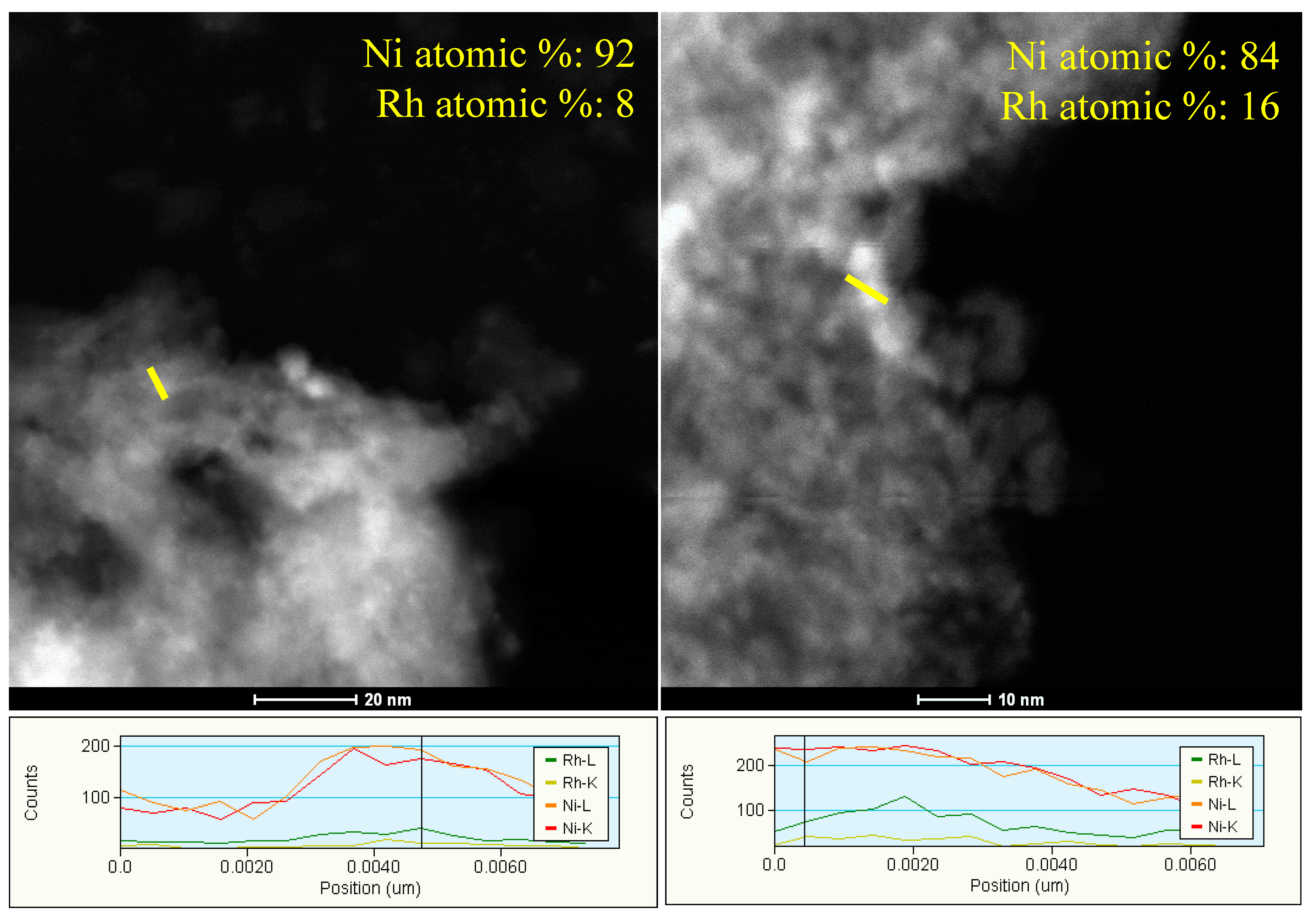
After the impregnation of the catalyst support by {NEt4}3{Ni10Rh(CO)19} and thermal decomposition at 160 °C, as displayed by EDX (Energy-dispersive X-ray spectroscopy) analyses on different spots (Figure 2), the solid was totally covered by small metal particles dispersed over the support surface. The compositional profiles of the solid confirmed the co-presence of Ni and Rh revealing an average Ni/Rh atomic ratio between 5 and 11.
After calcination, the 2NiRh cluster (C) and 3NiRh C catalysts exhibited comparable specific surface areas of ~80 m2/g (Table 1), while the increase of the metal loading led to a dramatic decrease to 48 m2/g in the case of 5NiRh C sample. A slight decrease of specific surface area was also observed for the catalyst obtained by incipient wetness impregnation (IWI) (60 m2/g).
Independently from the method used for the incorporation of Ni and Rh, after calcination at 900 °C, all the Ni–Rh/Mg/Al catalysts were composed by almost the same crystalline phases. The XRD patterns of the samples (Figure 1 left) showed the presence of an intense series of peaks related to MgO, according to the high Mg2+/Al3+ ratio of the catalyst support (4.0 as atomic ratio) together with the formation of a spinel phase composed mainly by Mg and Al (MgAl2O4). The peaks related to the presence of Ni and Rh oxides were not observed. It is noteworthy that, as previously reported [52,56], the formation of Mg/Ni/O and Ni(Mg)Al(Rh)2O4 phases very likely occurred at such high temperature, consequently leading to the development of strong metal–support interactions (SMSI) under reducing conditions.
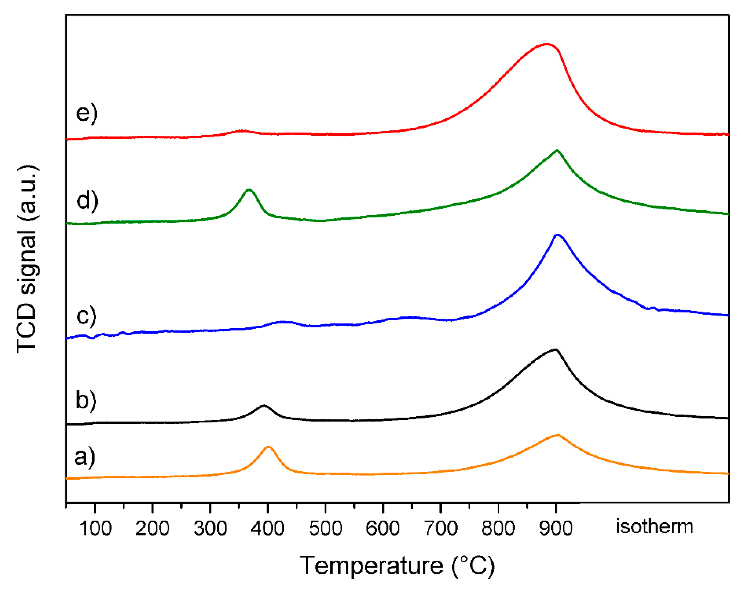
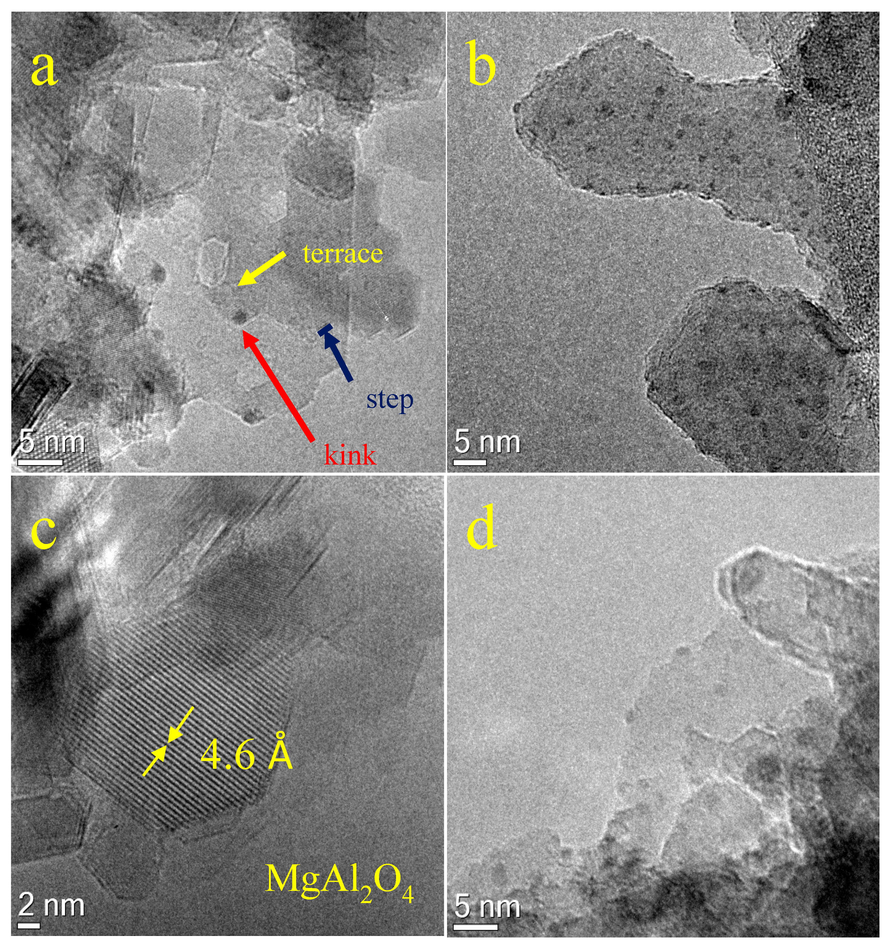
The H2-TPR (temperature-programmed reduction) experiments of the calcined catalysts performed over a broad range of temperatures are reported in Figure 3. The peak located in the lower temperature region was assigned to the reduction of highly stabilized Rh3+ species, that occurred in the 350–400 °C range. Notably, this peak became almost negligible for the 5NiRh C sample (Figure 3), suggesting the presence of larger Rh0 particles deposited from the metal cluster used, difficult to be oxidized and/or reduced. Conversely, the moderate Rh activation observed in the co-precipitated catalyst (3NiRh CP), was likely related to a partial presence of Rh species in the bulk phase. The peak detected around 900 °C was attributed to the reduction of Ni2+ species stabilized by the MgO matrix or partially present as NiAl2O4 phase. Comparing the results obtained for catalysts with a nominal Ni load of 3.0 wt % (Figure 3) it is possible to observe that the reducibility in this region was easier for the 3NiRh C and 3NiRh CP catalysts, suggesting stronger interaction between Ni and Rh, that catalyzes the reduction of Ni2+ species by H2-spillover, decreasing its reduction temperature. The formation of metal nanoparticles was confirmed by the HRTEM images of the catalysts after the H2-TPR experiments (Figure 4), showing the presence of small and highly dispersed metal particles (Figure 4a,b,d) embedded in or deposited on the MgO and MgAl2O4 matrix (Figure 4c). The average size of the formed nanoparticles was comparable among the catalysts at around 2–3 nm; notably the 3NiRh C catalyst showed a marked and spread presence of active species located in kink positions, and was thus reasonably more active in the reaction.

2.2. Combined Steam and Dry Reforming of Clean Biogas

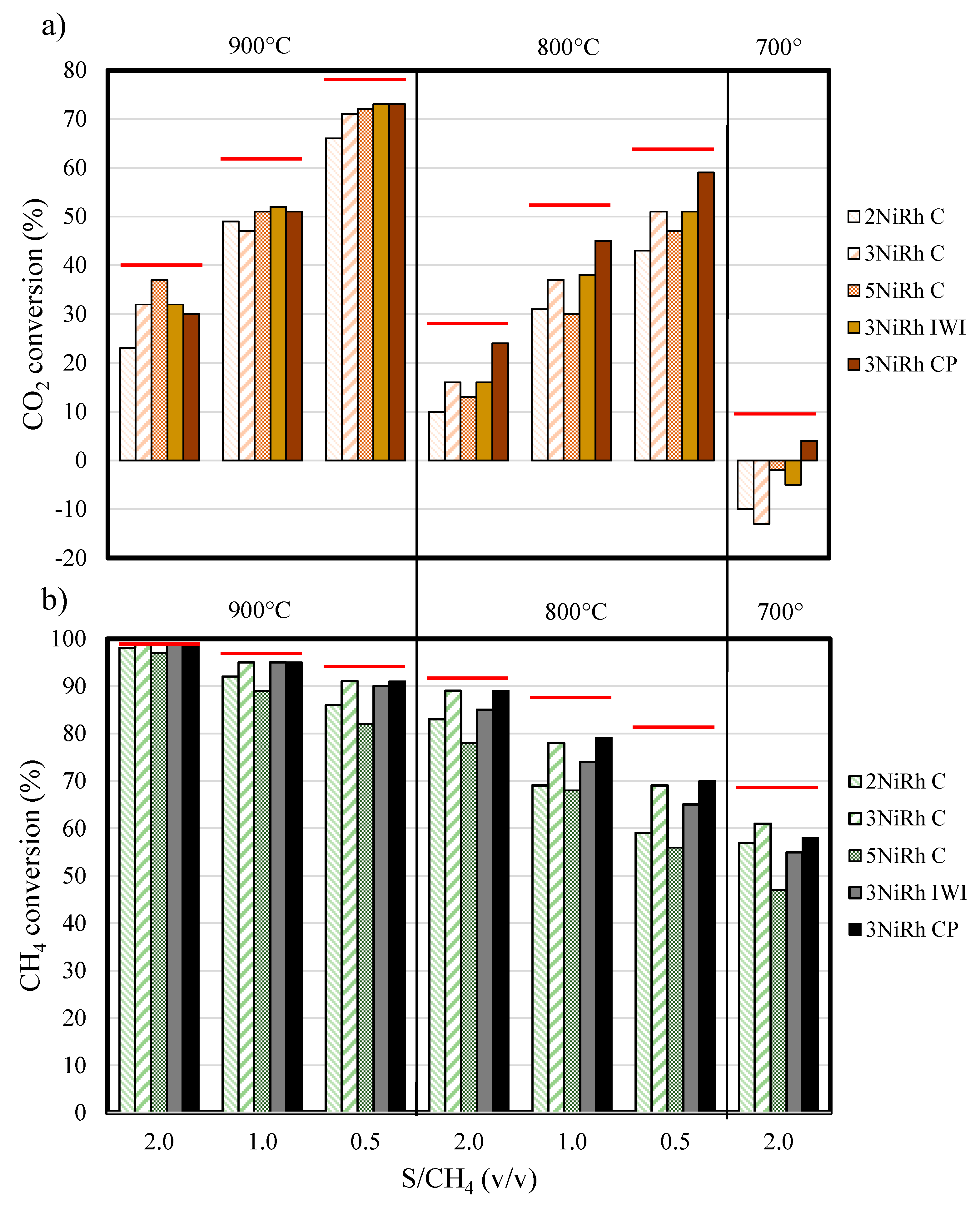
The performances of the catalysts were studied at decreasing temperature steps, varying the amount of steam in the inlet stream (Figure 5a,b). Hence, it was possible to evaluate the conditions in which CB could be better valorized. The biogas conversion values calculated at the thermodynamic equilibrium (red lines in Figure 5) showed that the CH4 conversion was less affected by the amount of water fed. As expected, by decreasing the S/CH4 ratio, the experimental CO2 conversion was highly enhanced, while the CH4 conversion lightly decreased. Almost every catalyst tested at 900 °C achieved CH4 conversion values close to thermodynamic equilibrium, while the CO2 conversions approached the equilibrium values only at 900 °C, S/CH4 = 0.5. With a low metal loading (2NiRh C catalyst) it was possible to obtain high conversions of CH4 at 900 °C even at low S/CH4 ratio (CH4 conversion = 86% at S/CH4 = 0.5), where over the 65% of CO2 was also converted. Decreasing the reaction temperature to 800 °C, 2NiRh C turned to be sensibly less active especially in terms of CO2 conversion, with a poor result of 10% at S/CH4 = 2.0. When the Ni–Rh cluster was impregnated to obtain a Ni load of 3.0 wt % (3NiRh C), the catalyst exhibited superior catalytic performances in all the reaction conditions investigated. Remarkably, 70% of the CO2 fed was converted at 900 °C and almost 90% of the CH4 was valorized even at 800 °C (S/CH4 = 2.0).
Surprisingly, increasing the metal loading to 5.0 wt % of Ni (Rh = 0.9 wt %) the catalytic performances drastically decreased, reaching the lowest values of CB conversion among the tested systems, e.g., at 700 °C most of the CH4 remained unreacted. The “volcano trend” observed with the increase of the amount of active phase may be explained considering the poor 5NiRh C catalyst activation in reducing conditions (H2-TPR, Figure 3). Although the larger and stable Rh0 particles obtained after calcination were active for the reaction, the synergic interactions between Ni–Rh were not strong enough to promote the activity of the Ni-species, hardly reducible and thus less active in the combined reforming.
To make a comparison between the promising activity of these novel catalysts with those attainable incorporating the active phase through the largely employed IWI and coprecipitation of a hydrotalcite-type precursor (CP) techniques, two catalysts with the same composition of the 3NiRh C sample were prepared and labelled as 3NiRh IWI and 3NiRh CP, respectively. Remarkably, 3NiRh C outperformed the 3NiRh IWI catalyst in terms of CH4 conversion at 800 and 700 °C, with no significant differences in the amount of CO2 converted. The possibility to valorize the CB using catalysts with low metal loadings was further confirmed by the 3NiRh CP sample. Starting from the results obtained in our previous work [52] in which the performances of different Ni-based catalysts obtained by CP were assessed (Ni loading of 10 wt %), the amount of active phase was reduced and the catalytic results attained (Figure 5) showed a remarkable improvement of activity especially in terms of CO2 conversion, while the amount of CH4 processed was comparable to the one displayed by the 3NiRh C catalyst.
It is noteworthy that, for all the catalyst tested, the occurrence of the water gas shift (WGS) reaction was not negligible at 700 °C. The excess of steam in the inlet stream drastically reduced the CO2 conversion, which turned towards negative values in most of the cases (with the exception of the 3NiRh CP catalyst, c.a. 5%). This behavior was confirmed by the high H2/CO values of the syngas produced (~ 3 as molar ratio at 700 °C). Repeating the test at 900 °C (S/CH4 = 2) at the end of the cycle of experiments no loss of activity was detected, evidencing the high stability of the different investigated catalysts also in harsh reaction conditions.
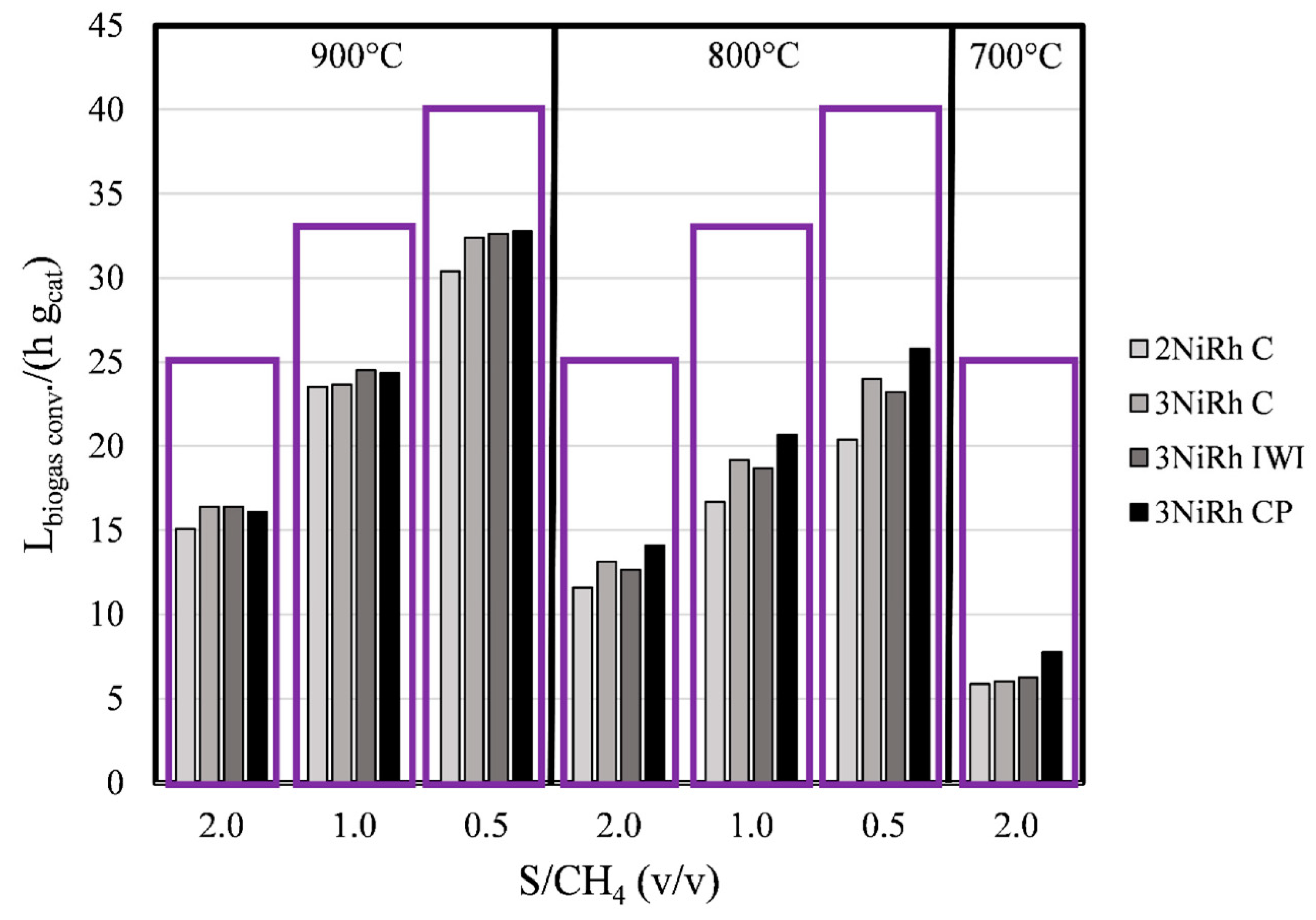
The productivity of the process in the different operating conditions was calculated by considering the overall volumes of CB converted (as the sum of CO2 and CH4 valorized) expressed as LBGconv. h−1 gcat−1 (Figure 6). The competition between the two main reforming reactions led to significant differences regarding the composition of the outlet syngas as well as the amount of CB processed. Depending on the amount of water fed, it was possible to modulate the H2/CO ratio in the outlet stream (Figure S3). Notably, when the S/CH4 value was 0.5, high volumes of CB were converted, achieving the 82% of the total fed at 900 °C and producing a syngas with a H2/CO ratio of 1.2 (v/v). Conversely, in excess of steam, the amount of CB processed slightly decreased (65% at 900 °C and 55% at 800 °C), but the significant occurrence of the SR and WGS reactions enriched the H2 content in the syngas, that exhibited H2/CO values in the range 2–2.3 (v/v). Such a wide variety of syngas compositions was attainable by modulating the reaction conditions, further evidencing the potentiality of the combined reforming to valorize a large volume of CB without using further steps in its upgrading process, thus producing a syngas exploitable in downstream applications such as Fischer–Tropsch or methanol synthesis. Finally, the results obtained in the different conditions were normalized on the amount of catalytic active phase loaded (Ni + Rh), expressing the results in terms of volume of CB converted per hour and gram of active phase (L(CH4 + CO2) h−1 g(Ni + Rh)−1). The obtained values were compared to the biogas conversions previously reported in the literature, in Table 2.
Considering the harsh reaction conditions used in this work, especially in terms of operating pressure and S/CH4 values, it was possible to assert that the catalysts tested were promising for the combined reforming of biogas even at low temperature. It is noteworthy that, even at 700 °C, the value of biogas converted per gram of active phase was highly competitive to that observed for other Ni-based catalysts, reaching an outstanding value of 926 L h−1 g(Ni + Rh)−1 at 900 °C when a S/CH4 of 0.50 was used.

2.3. Characterization of Spent Catalysts

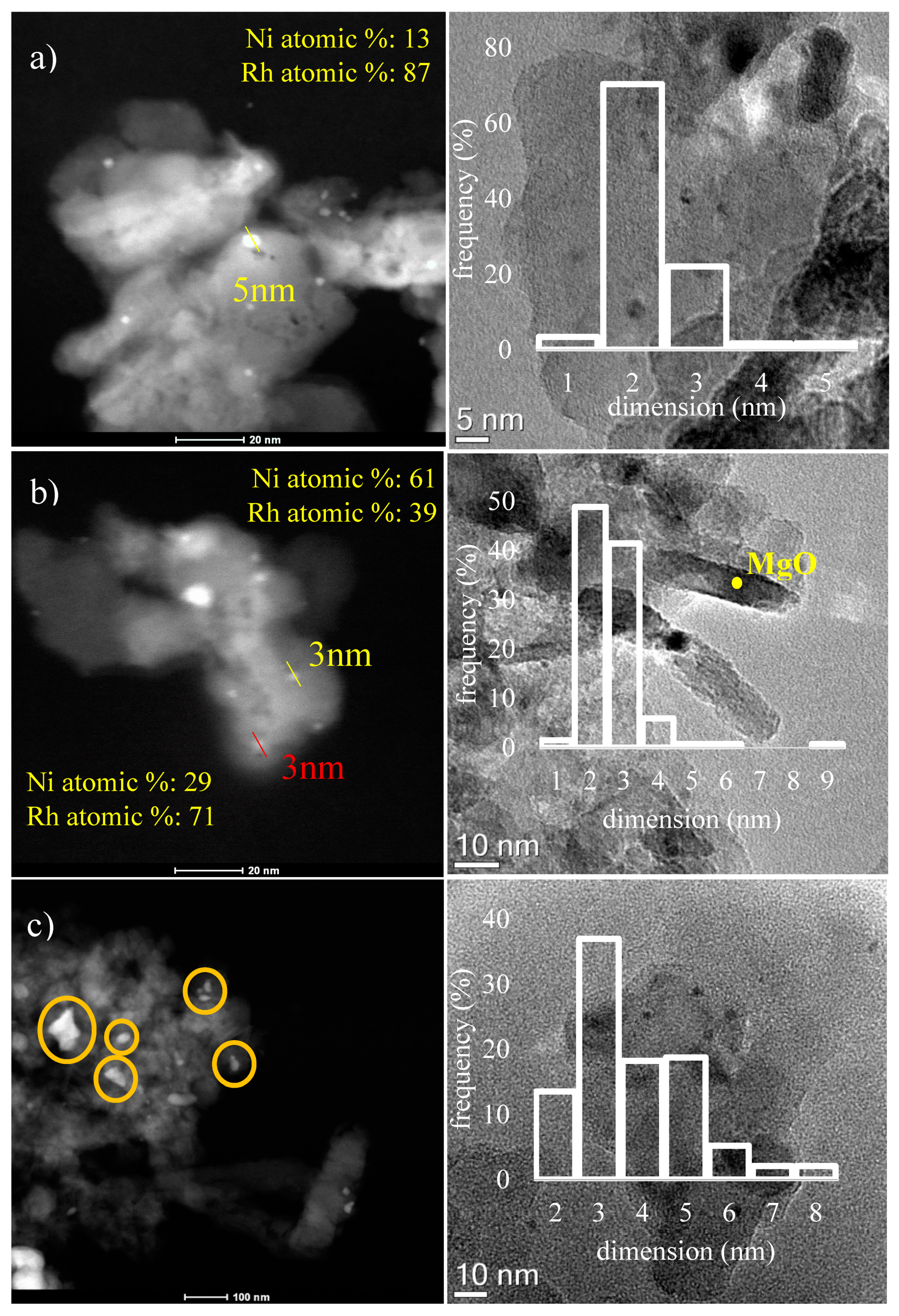
To shed light on the reasons behind the different catalytic performances and to correlate the properties of the catalysts with the method of active metal incorporation, the catalysts were deeply characterized after reaction by HRTEM, XRD, BET and Raman analyses. The harsh reaction conditions used caused a loss of specific surface area for all the tested catalysts (Table 1) that reached a value down to 26 m2 g−1 for the 3NiRh IWI sample. Although this decrease also caused an increase of crystallinity in the catalysts, the XRD patterns of the spent catalysts (Figure S4) did not evidence any peak related to the presence of Ni0 or Rh0 phases, testing the good dispersion and stability of the active species. From the HRTEM and HAADF (high-angle annular dark field) images (Figure 7) it was possible to determine the statistical distribution of the metal particles and the composition of them as a function of their dimension.
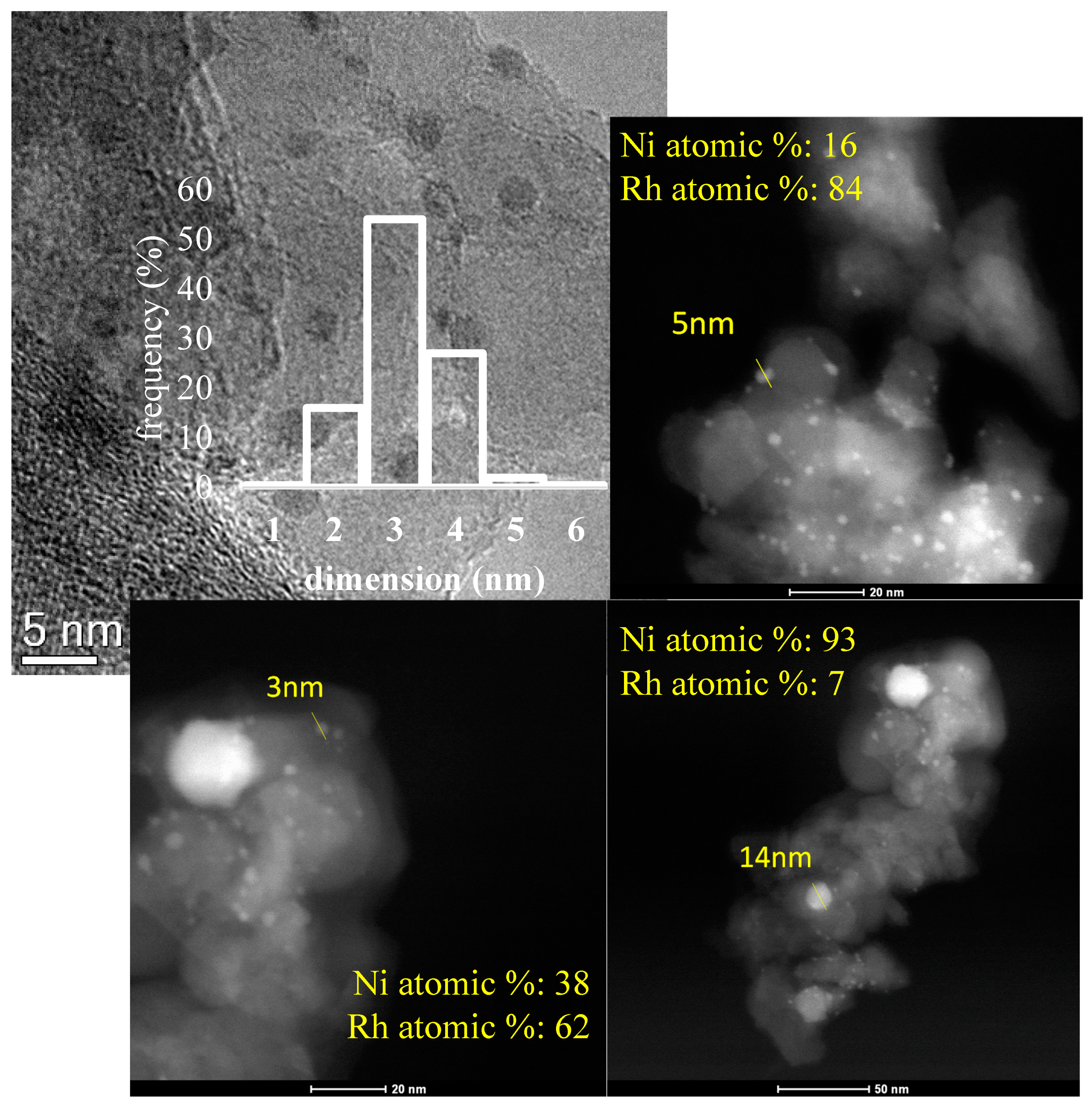
To some extent, all the tested catalysts showed two distinct particles domains that were characterized by a different distribution between small and highly active nanoparticles and the formation of larger agglomerates (d > 20 nm), whose presence significantly varied among the samples. The best active phase dispersion was achieved for the 2NiRh C catalyst (Figure 7a), that exhibited an average diameter of the formed nanoparticles around 2.5 nm. Although the presence of some particles with a larger diameter of ~16 nm was detected, the active phase was well distributed on the surface of the catalyst and exhibited the co-presence of Ni and Rh, confirming the stability of the bimetallic alloy formed during reaction/reduction. The average particle diameter varied as a function of the metal loading of the catalysts, consequently affecting the statistical distribution of the active sites and consequently the catalytic activity. The 3NiRh C catalyst (Figure 7b) displayed a narrow distribution of the Ni–Rh nanoparticles centered around 2–3 nm, while when the metal loading increased, the particle distribution became wider, further revealing a significance presence of active particles with a diameter higher than 4 nm (~50% of the total). Furthermore, also due to the low surface area displayed after calcination (48 m2/g), a widespread presence of large sintered metal aggregates (up to ~100 nm) composed by Ni and Rh was observed (Figure 7c). The formation of such large particles was likely the responsible for the loss of activity observed during the catalytic tests. Similarly, for the 3NiRh IWI catalyst (Figure 8), the formation of small Ni–Rh particles (with a distribution centered around 3 nm) occurred together with a conspicuous presence of larger particles with a diameter between 10 and 20 nm.
Comparing the results obtained at equal metal loading, it is possible to assert that the type of precursor used for the Ni–Rh incorporation process significantly affected the formation of the nanoparticles and their resistance to sintering phenomena during the catalytic tests. These properties were improved using the Ni10Rh(CO)19 cluster that assured a better interaction between Ni and Rh, promoting the formation of highly active sites.
Regarding the composition of the nanoparticles, the overall Ni and Rh content varied as a function of the particle dimension. For example, the active particles in the 3NiRh C catalyst were composed by variable amounts of the two metals, while the smaller nanoparticles showed a high content of Rh (30–70 as atomic%), the larger particles (>9 nm) formed by Ni sintering are Ni enriched and showed a negligible Rh content. The same trend was observed for the other catalysts, confirming that the presence of Rh promoted the stabilization of the Ni0 particles by the formation of a bimetallic alloy. Further investigating the carbon formation during reaction, Raman spectra on different spots of the catalysts were recorded (Figure S5). For all tested systems, the analyses did not show a widespread presence of carbonaceous material, as it is locally lightly deposited (mainly as nanotubes) over the 3NiRh C catalyst surface only, showing the characteristic G and D bands attributable to the formation of graphite and defects, respectively. It is noteworthy that this particular result can be attributable to the remarkable activity of the catalyst, that can at same extent allow also the CH4 decomposition, especially at 900 °C and at low S/CH4 ratios.

3. Material and Methods

3.1. Preparation of the Catalysts

The chemicals used for the synthesis were rhodium (III) nitrate solution (~10 wt % (Rh in >5 wt % HNO3), Sigma Aldrich, St. Louis, MO, USA), nickel (II) nitrate hexahydrate (Sigma Aldrich, 99%), magnesium nitrate hexahydrate (Sigma Aldrich, 99%) and aluminum nitrate nonahydrate (Aldrich Sigma, 98%). The coprecipitation of the hydrotalcite type precursors were carried out by preparing a solution of Ni2+, Mg2+, Al3+, Rh3+ nitrates ((Ni,Mg)2+/(Al,Rh3+) = 4 as atomic ratio, 2 M) in deionized water. Coprecipitation occurred by the dropwise addition of this solution into a Na2CO3 aqueous solution (1 M) at a constant temperature of 60 °C and pH 10. During the synthesis, the pH value was kept constant by addition of a NaOH aqueous solution (3 M). After the aging of the solid for 60 min, the obtained precipitate was filtered and washed with deionized water to obtain a residual Na2O content below the 0.01 wt %. The solid was then dried at 70 °C overnight and calcined at 900 °C for 6 h. When incipient wetness impregnation (IWI) was used to incorporate nickel and rhodium on the catalyst support, the metal nitrates aqueous solution was added to the coprecipitated HT support calcined at 900 °C, composed by MgO and MgAl2O4 and with a Mg2+/Al3+ atomic ratio of 4 to attain a final load of Ni and Rh of 3 and 0.5 wt %, respectively. The obtained solid was dried at 70 °C, (overnight) and then calcined at 900 °C for 6 h [52,63]. The synthesis of the Ni/Rh cluster used to disperse the active metals on the surface of the catalytic support is widely described elsewhere [64]. In this case, a proper amount of the {NEt4}3{Ni10Rh(CO)19} cluster (Figure S1) to reach a final load of 2.0, 3.0 or 5.0 wt % of Ni (and consequently 0.3, 0.5 or 0.9 wt % of Rh) was maintained in inert atmosphere and dissolved in CH3CN (20 mL). When the catalytic support as powder was added to the solution, the obtained suspension was stirred for 12 h and then dried. The decomposition of the deposited cluster was carried out by a thermal treatment of the solid at 160 °C for 8 h. To confirm the deposition/decomposition of the cluster, infrared (IR) analyses were carried out (Figure S2). The obtained solid was then calcined at 900 °C for 6 h. The name and the composition of the catalysts are reported in Table 3.

3.2. Characterization Techniques

The crystalline structure of the solids was determined by XRD powder analyses. The instrument used was a PANalytical X’Pert diffractometer (Spectris, Egham, UK) equipped with a copper anode (λCu Kα = 0.15418 nm) and a fast X’Celerator detector (2θ range: 5–80°, step size: 0.1°, time per step: 2 s).
The specific surface area values of the catalysts were determined by BET method. The instrument used was a Carlo Erba Sorpty instrument (CARLO ERBA, Milano, Italy) [65]. The catalysts (~0.2 g) were pre-treated under vacuum at 150 °C for 30 min and analyzed at −196 °C (liquid N2).
The H2-TPR and CO2-TPD experiments were carried out in a Autochem II (Chemisorption analyzer, Micromeritics) (Micromeritics, Norcross, GA, USA). In a typical H2-TPR analysis, the calcined catalyst (~0.1 g) was pre-treated at 550 °C for 1 h under 30 mL min−1 of He. After cooling of the sample to 50 °C, the carrier gas was switched to 5% (v/v) H2/Ar (30 mL min−1) and the temperature of the catalyst increased to 900 °C (10 °C min−1), holding this temperature for 1 h. The signal was measured by means of a thermal conductivity detector (TCD). The CO2-TPD experiments were carried out after the pretreatment of the solid at 500 °C (He, 30 mL min−1). The CO2 adsorption was carried out by flowing a constant flow of 10% (v/v) CO2/Ar (30 mL min−1) mixture for 2 h. The physiosorbed CO2 was removed by using a flow of He (1 h). The desorbed CO2 was monitored by heating up the solid to 500 °C (10 °C min−1) under a stream of He. The CO2 evolved was recorded through a Cirrus 2 (MKS Instruments) online mass spectrometer (MKS Instruments, Andover, MA, USA).
A TEM/STEM FEI TECNAI F20 microscope (Thermo Fisher Scientific, Waltham, MA, USA) equipped with an EDX analyzer was utilized for the high-resolution transmission electron microscopy (HRTEM) characterization. The solid was deposited on an Au grid with lacey multi-foil carbon film and the statistical distribution of the formed metal nanoparticles was determined by measuring the diameter of at least 200 particles [66].
The instrument used for the Raman spectroscopy analyses of the catalysts after reaction was a Renishaw RM1000 instrument (Renishaw plc, Wotton-under-Edge, UK). The beam laser used was green (Ar+ 514.5 nm, relative power used: 10%) and the analyses were conducted in the 2000–800 cm−1 region (acquisition time: 10 s, 10 accumulations) [67,68].

3.3. Catalytic Activity

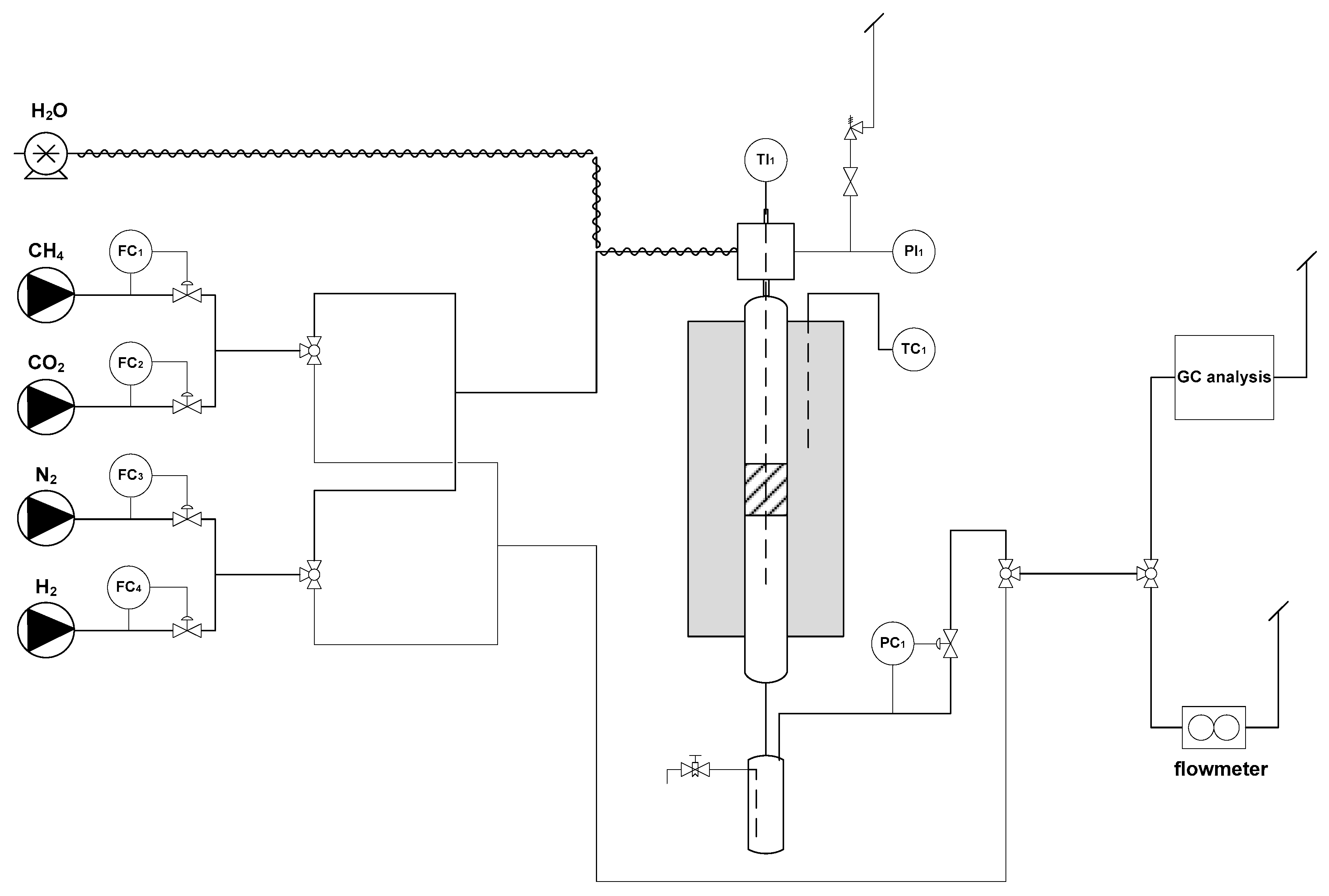
The catalysts after calcination (powder) were pressed at 10 t for 20 min and subsequently crushed and sieved to a dimensional range of 30–40 mesh (0.420–0.595 mm). The catalysts (~1 g) were charged in a tubular reactor (INCOLOY 800 HT, ∅ = 0.8 cm) placed into an electric tubular furnace. The process gasses (CH4, CO2, N2, H2) flow rate was adjusted by thermal mass flowmeters (BROOKS Instruments, Hatfield, PA, USA) while water was fed to the reactor using an HPLC pump (Jasco, Tokyo, Japan) and a steam generator (T: 215 °C). The outlet stream was sent to a gas liquid separator operating at 1 °C followed by a back-pressure regulator (Swagelok, Solon, OH, USA). The analysis section consisted of a gas flowmeter (Figure 9) and an online gas chromatograph (Agilent Technologies 7890A, Santa Clara, CA, USA) equipped with a CarboPLOT P7 (carried gas H2, determination of CO, CO2 and CH4) and HP-Molesieve (carrier gas N2, determination of H2) columns and two TCD.
The activation of the catalysts was performed in-situ before the catalytic tests by continuously flowing of H2/N2 (1/10 v/v, 200 mL min−1) increasing the catalyst temperature from 300 to 900 °C with a slope of 5 °C min−1, and holding the final temperature for 1 h. After reduction, the catalysts were tested in the combined reforming reaction at 0.5 MPa, feeding a 1/1 (v/v) mixture of CH4 and CO2 and working at a constant GHSV of 50,000 mL h−1 gcat−1. The catalytic activities were measured by changing the temperature of the oven from 900 to 700 °C and using steam to methane ratios (S/CH4) values of the inlet stream of 2.0, 1.0 and 0.5 (v/v) (Table 4). Using a thermocouple sliding a capillary inserted into the catalytic bed it was possible to monitor the thermal profile during reaction.
The CH4 and CO2 conversion values were calculated using the following equation:
Conversion   = ( F i n   ×   y i n )   -   ( F o u t   ×   y o u t ) ( F i n   × y i n )   ×   100
where F was the CH4 or CO2 flow rate and y was the molar fraction of CH4 or CO2 in the inlet (in) or outlet (out) stream. The calculations of the conversion values at the thermodynamic equilibrium were carried out using the CEAgui software by NASA [69].

4. Conclusions

The combined reforming of clean biogas using Ni–Rh/Mg/Al/O catalysts is a promising way to valorize CO2, producing a syngas directly suitable for further downstream applications such as methanol or Fischer–Tropsch synthesis. Through the use of a pre-formed bimetallic cluster precursor, it was possible to obtain an optimized composition with low metal loading (down to 3.0 wt % of Ni) and to emphasize the interaction between Ni and Rh, promoting the formation of highly active and stable sites.
After reduction and reaction, the catalysts showed a high dispersion of the active phase, composed by a Ni–Rh alloy, highly active and stable in the harsh reaction conditions. When the metal loading was increased beyond optimum value, a dramatic decrease of activity was observed ascribable to the sintering of the active phase, with the formation of large agglomerates, mainly composed by Ni.

Supplementary Materials

The following are available online at https://www.mdpi.com/2073-4344/10/11/1345/s1, Figure S1: Structure of the {Ni10Rh(CO)19} cluster, Figure S2: IR spectra of {Ni10Rh(CO)19} before and after thermal decomposition, Figure S3: H2/CO ratio of the outlet stream as a function of the reaction conditions, Figure S4: XRD patterns of the catalysts after reaction, Figure S5: Raman results obtained for the spent catalysts.

Author Contributions

Conceptualization, N.S., C.L., A.V. and M.C.I.; validation, N.S., C.L. and A.V.; formal analysis, A.C.; investigation, N.S., A.C., M.C.I.; writing—original draft preparation, N.S. and C.L.; writing—review and editing, A.V., N.S., C.L. and G.F.; supervision, G.F. and A.V.; All authors have read and agreed to the published version of the manuscript.

Funding

This research received no external funding.

Conflicts of Interest

The authors declare no conflict of interest.

References

  1. Stürmer, S.; Leiers, D.; Anspach, V.; Brügging, E.; Scharfy, D.; Wissel, T. Agricultural biogas production: A regional comparison of technical parameters. Renew. Energy 2021, 164, 171–182. [Google Scholar] [CrossRef]
  2. Naverro-Puyuelo, A.; Reyero, I.; Moral, A.; Bimbela, F.; Bañares, M.A.; Gandìa, L.M. Effect of oxygen addition, reaction temperature and thermal treatments on syngas production from biogas combined reforming using Rh/alumina catalysts. J. Ind. Eng. Chem. 2019, 80, 217–226. [Google Scholar] [CrossRef]
  3. Rasi, S.; Veijanen, A.; Rintala, J. Trace compounds of biogas from different biogas production plants. Energy 2007, 32, 1375–1380. [Google Scholar] [CrossRef]
  4. Rasi, S.; Lantela, J.; Rintala, J. Trace compounds affecting biogas energy utilisation, A review. Energy Convers. Manag. 2011, 52, 3369–3375. [Google Scholar] [CrossRef]
  5. Sosnowski, P.; Wieczorek, A.; Ledakowicz, S. Anaerobic co-digestion of sewage sludge and organic fraction of municipal solid wastes. Adv. Environ. Res. 2003, 7, 609–616. [Google Scholar] [CrossRef]
  6. Luostarinen, S.; Luste, S.; Sillanpaa, M. Increased biogas production at wastewater treatment plants through co-digestion of sewage sludge with grease trap sludge from a meat processing plant. Bioresour. Technol. 2009, 100, 79–85. [Google Scholar] [CrossRef]
  7. Johnsonn, O.; Pullman, E.; Jensen, J.K.; Eklund, R.; Schyl, H.; Ivarsson, S. Sustainable Gas Enters the European Gas Distribution System; Danish Gas Technology Centre: Hørsholm, Denmark, 2003. [Google Scholar]
  8. Chen, Y.; Cheng, J.J.; Creamer, K.S. Inhibition of Anaerobic Digestion Process: A Review. Bioresour. Technol. 2008, 99, 4044–4064. [Google Scholar] [CrossRef]
  9. Holm-Nielsen, J.B.; Al Seadi, T.; Oleskowicz-Popiel, P. The future of anaerobic digestion and biogas utilization. Bioresour. Technol. 2009, 100, 5478–5484. [Google Scholar] [CrossRef]
  10. Neto, J.G.; Ozorio, L.V.; de Abreu, T.C.C.; dos Santos, B.F.; Pradelle, F. Modeling of biogas production from food, fruits and vegetables wastes using artificial neural network (ANN). Fuel 2021, 285, 119081. [Google Scholar] [CrossRef]
  11. Renewables 2017 Global Status Report; Renewable Energy Policy Network for the 21thCentury REN21; REN21: Paris, France, 2017.
  12. Van Nes, W.J.; Nhete, T.D. Biogas for a better life: An African initiative. Renew. Energy World 2007, 10, 184–187. [Google Scholar]
  13. Scarlat, N.; Dallemand, J.F.; Fahl, F. Biogas: Developments and perspectives in Europe. Renew. Energy 2018, 129A, 457–472. [Google Scholar] [CrossRef]
  14. Andriani, D.; Wresta, A.; Atmaja, T.D.; Saepudin, A. A review on Optimization Production and Upgrading Biogas Through CO2 Removal Using Various Techniques. Appl. Biochem. Biotechnol. 2014, 172, 1909–1928. [Google Scholar] [CrossRef] [PubMed]
  15. Akinyele, D.O.; Rayudu, R.K. Review of energy storage technologies for sustainable power networks. Sustain. Energy Technol. Assess. 2014, 8, 74–91. [Google Scholar] [CrossRef]
  16. Smith, A.D.; Mago, P.J.; Fumo, N. Benefits of thermal energy storage option combined with CHP system for different commercial building types. Sustain. Energy Technol. Assess. 2013, 1, 3–12. [Google Scholar] [CrossRef]
  17. Yang, L.; Ge, X.; Wan, C.; Yu, F.; Li, Y. Progress and perspectives in converting biogas to transportation fuels. Renew. Sustain. Energy Rev. 2014, 40, 1133–1152. [Google Scholar] [CrossRef]
  18. Abbaszaadeh, A.; Ghobadian, B.; Omidkhah, M.R.; Najafi, G. Current biodiesel production technologies: A comparative review. Energy Convers. Manag. 2012, 63, 138–148. [Google Scholar] [CrossRef]
  19. Hahn, H.; Hartmann, K.; Bühle, L.; Wachendorf, M. Comparative life cycle assessment of biogas plant configurations for a demand oriented biogas supply for flexible power generation. Bioresour. Technol. 2015, 179, 348–358. [Google Scholar] [CrossRef]
  20. Kapdi, S.S.; Vijay, V.K.; Rajesh, S.K.; Prasad, R. Biogas scrubbing, compression and storage: Perspective and prospectus in Indian context. Renew. Energy 2005, 30, 1195–1202. [Google Scholar] [CrossRef]
  21. Subramanian, K.A.; Mathad, V.C.; Vijay, V.K.; Subbarao, P.M.V. Comparative Evaluation of Emission and Fuel Economy of an Automotive Spark Ignition Vehicle Fuelled with Methane Enriched Biogas and CNG Using Chassis Dynamometer. Appl. Energy 2013, 105, 17–29. [Google Scholar] [CrossRef]
  22. Shiga, H.; Shinda, K.; Hagiwara, K.; Tsutsumi, A.; Sakurai, M.; Yoshida, K.; Bilgen, E. Large-scale hydrogen production from biogas. Int. J. Hydrogen Energy 1998, 23, 631–640. [Google Scholar] [CrossRef]
  23. Wei, Q.; Gao, X.; Wang, L.; Ma, Q. Rational design of nickel-based catalyst coupling with combined methane reforming to steadily produce syngas. Fuel 2020, 271, 117631–117642. [Google Scholar] [CrossRef]
  24. Parente, M.; Soria, M.A.; Madeira, L.M. Hydrogen and/or syngas production through combined dry and steam reforming of biogas in a membrane reactor: A thermodynamic study. Renew. Energy 2020, 157, 1254–1264. [Google Scholar] [CrossRef]
  25. Simpson, A.P.; Lutz, A.E. Exergy analysis of hydrogen production via steam methane reforming. Int. J. Hydrogen Energy 2007, 32, 4811–4820. [Google Scholar] [CrossRef]
  26. Barelli, L.; Bidini, G.; Gallorini, F.; Servili, S. Hydrogen production through sorption-enhanced steam methane reforming and membrane technology: A Review. Energy 2008, 33, 554–570. [Google Scholar] [CrossRef]
  27. Lunsford, J.H. Catalytic conversion of methane to more useful chemicals and fuels: A challenge for the 21st century. Catal. Today 2000, 63, 165–174. [Google Scholar] [CrossRef]
  28. Muraza, O.; Galadima, A. A review on coke management during dry reforming of methane. Int. J. Energy Res. 2015, 39, 1196–1216. [Google Scholar] [CrossRef]
  29. Arora, S.; Prasad, R. An overview on dry reforming of methane: Strategies to reduce carbonaceous deactivation of catalysts. RSC Adv. 2016, 6, 108668–108688. [Google Scholar] [CrossRef]
  30. Nikoo, M.N.; Amin, N.A.S. Thermodynamic analysis of carbon dioxide reforming of methane in view of solid carbon formation. Fuel Process. Tech. 2011, 92, 678–691. [Google Scholar] [CrossRef] [Green Version]
  31. Istadi; Amin, N.A.S. Co-generation of synthesis gas and C2+ hydrocarbons from methane and carbon dioxide in a hybrid catalytic-plasma reactor: A review. Fuel 2006, 85, 577–592. [Google Scholar] [CrossRef]
  32. Wang, S.; Lu, G.Q.; Millar, G.J. Carbon Dioxide Reforming of Methane To Produce Synthesis Gas over Metal-Supported Catalysts: State of the Art. Energy Fuels 1996, 10, 896–904. [Google Scholar] [CrossRef]
  33. Zeppieri, M.; Villa, P.L.; Verdone, N.; Scarsella, M.; Filippis, P.D. Kinetic of methane steam reforming reaction over nickel- and rhodium-based catalysts. Appl. Catal. A Gen. 2010, 387, 147–154. [Google Scholar] [CrossRef]
  34. Richardson, J.T.; Garrait, M.; Hung, J.K. Carbon Dioxide Reforming with Rh and Pt-Re Catalysts Dispersed on Ceramic Foam Supports. Appl. Catal. A Gen. 2003, 255, 69–82. [Google Scholar] [CrossRef]
  35. Papurello, D.; Chiodo, V.; Maisano, S.; Lanzini, A.; Santarelli, M. Catalytic stability of a Ni-Catalyst towards biogas reforming in the presence of deactivating trace compounds. Renew. Energy 2018, 127, 481–494. [Google Scholar] [CrossRef]
  36. Dan, M.; Mihet, M.; Borodi, G.; Lazar, M.D. Combined steam and dry reforming of methane for syngas production from biogas using bimodal pore catalyst. Catal. Today 2020, in press corrected proof. [Google Scholar] [CrossRef]
  37. Pashchenko, D. Combined methane reforming with a mixture of methane combustion products and steam over a Ni-based catalyst: An experimental and thermodynamic study. Energy 2019, 185, 573–584. [Google Scholar] [CrossRef]
  38. Dan, M.; Mihet, M.; Lazar, M.D. Hydrogen and/or syngas production by combined steam and dry reforming of methane on nickel catalysts. Int. J. Hydrogen Energy 2020, 45, 26254–26264. [Google Scholar] [CrossRef]
  39. Horn, R.; Williams, K.A.; Degenstein, N.J.; Schmidt, L.D. Syngas by catalytic partial oxidation of methane on rhodium: Mechanistic conclusions from spatially resolved measurements and numerical simulations. J. Catal. 2006, 242, 92–102. [Google Scholar] [CrossRef]
  40. Jakobsen, J.G.; Jørgensen, T.L.; Chorkendorff, I.; Sehested, J. Steam and CO2 reforming of methane over Ru/ZrO2 catalyst. Appl. Catal. A Gen. 2010, 377, 158–166. [Google Scholar] [CrossRef]
  41. Souza, M.M.V.M.; Neto, O.R.M.; Schmal, M. Synthesis Gas Production from Natural Gas on Supported Pt Catalysts. J. Nat. Gas. Chem. 2006, 15, 21–27. [Google Scholar] [CrossRef]
  42. Hou, Z.; Chen, P.; Fang, H.; Zheng, X.; Yashima, T. Production of synthesis gas via methane reforming with CO2 on noble metals and small amount of noble-(Rh-) promoted Ni caltaysts. Int. J. Hydrogen Energy 2006, 31, 555–561. [Google Scholar] [CrossRef]
  43. Cavani, F.; Trifirò, F.; Vaccari, A. Hydrotalcite-type anionic clays: Preparation, properties and applications. Catal. Today 1991, 11, 173–291. [Google Scholar] [CrossRef]
  44. Vaccari, A. Preparation and catalytic properties of cationic and anionic clays. Catal. Today 1998, 41, 53–71. [Google Scholar] [CrossRef]
  45. Rives, V. Layered Double Hydroxides: Present and Future; Nova Publ.: New York, NY, USA, 2001. [Google Scholar]
  46. Zhang, F.; Xiang, X.; Li, F.; Duan, X. Layered Double Hydroxides as Catalytic Materials: Recent Development. Catal. Surv. Asia 2008, 12, 253–265. [Google Scholar] [CrossRef]
  47. Carrado, K.A.; Kostapapas, A.; Suib, S.L. Layered double hydroxides (LDHs). Solid State Ion. 2008, 26, 77–86. [Google Scholar] [CrossRef]
  48. Xu, Z.P.; Zhang, J.; Adebajo, M.O.; Zhang, H.; Zhou, C. Catalytic applications of layered double hydroxides and derivatives. Appl. Clay Sci. 2011, 53, 139–150. [Google Scholar] [CrossRef]
  49. Fan, G.; Li, F.; Evans, D.G.; Duan, X. Catalytic applications of layered double hydroxides: Recent advances and perspectives. Chem. Soc. Rev. 2014, 43, 7040–7066. [Google Scholar] [CrossRef]
  50. Hernandez, W.Y.; Lauwaert, J.; Van Der Voort, P.; Verberckmoes, A. Recent advances on the utilization of layered double hydroxides (LDHs) and related heterogeneous catalysts in a lignocellulosic-feedstock biorefinery scheme. Green Chem. 2017, 19, 5269–5302. [Google Scholar] [CrossRef] [Green Version]
  51. Li, P.; Yu, F.; Altaf, N.; Zhu, M.; Li, J.; Dai, B.; Wang, Q. Two-Dimensional Layered Double Hydroxides for Reactions of Methanation and Methane Reforming in C1 Chemistry. Materials 2018, 11, 221. [Google Scholar] [CrossRef] [Green Version]
  52. Schiaroli, N.; Lucarelli, C.; Sanghez de Luna, G.; Fornasari, G.; Vaccari, A. Ni-based catalysts to produce synthesis gas by combined reforming of clean biogas. Appl. Catal. Ageneral 2019, 582, 117087–117099. [Google Scholar] [CrossRef]
  53. Lucrédio, A.F.; Assaf, J.M.; Assaf, E.M. Reforming of a model sulfur-free biogas on Ni catalysts supported on Mg(Al)O derived from hydrotalcite precursors: Effect of La and Rh addition. Biomass Bioenergy 2014, 60, 8–17. [Google Scholar] [CrossRef]
  54. Diez, V.; Ferretti, C.; Torresi, P.; Apesteguia, C.R.; Di Cosimo, J.I. Effect of MgO activation conditions on its catalytic properties for base-catalyzed reactions. Catal. Today 2017, 173, 21–27. [Google Scholar] [CrossRef]
  55. Selvamani, T.; Sinhamahapatra, A.; Bhattacharjya, D.; Mukhopadhyay, I. Rectangular MgO microsheets with strong catalytic activity. Mater. Chem. Phys. 2011, 129, 853–861. [Google Scholar] [CrossRef]
  56. López-Fonseca, R.; Jiménez-González, C.; de Rivas, B.; Gutiérrez-Ortiz, J.I. Partial oxidation of methane to syngas on bulk NiAl2O4 catalyst. Comparison with alumina supported nickel, platinum and rhodium catalysts. Appl. Catal. A Gen. 2012, 437–438, 53–62. [Google Scholar]
  57. le Saché, E.; Pastor-Pérez, L.; Garcilaso, V.; Watson, D.J.; Centeno, M.A.; Odriozola, J.A.; Reina, T.R. Flexible syngas production using a La2Zr2-xNixO7-δ pyrochlore-double perovskite catalyst: Towards a direct route for gas phase CO2 recycling. Catal. Today 2020, 357, 583–589. [Google Scholar] [CrossRef]
  58. Olah, G.A.; Goeppert, A.; Czaun, M.; Prakash, G.K.S. Bi-reforming of methane from any source with steam and carbon dioxide exclusively to metgas (CO-2H2) for methanol and hydrocarbon synthesis. J. Am. Chem. Soc. 2013, 135, 648–650. [Google Scholar] [CrossRef] [PubMed]
  59. Garcìa-Diéguez, M.; Pieta, I.S.; Herrera, M.C.; Larrubia, M.A.; Alemany, L.J. RhNi nanocatalysts for the CO2 and CO2+H2O reforming of methane. Catal. Today 2011, 175, 136–142. [Google Scholar] [CrossRef]
  60. Jabbour, K.; El Hassan, N.; Davidson, A.; Casale, S.; Massiani, P. Factors affecting the long-term stability of mesoporous nickel-based catalysts in cobined steam and dry reforming of methane. Catal. Sci. Technol. 2016, 6, 4616–4631. [Google Scholar] [CrossRef] [Green Version]
  61. Álvarez, A.; Centeno, M.Á.; Odriozola, J.A. Ru-Ni Catalyst in the Combined Dry-Steam Reforming of Methane: The Importance in the Metal Order Addition. Top. Catal. 2016, 59, 303–313. [Google Scholar] [CrossRef]
  62. Li, W.; Zhao, Z.; Ren, P.; Wang, G. Effect of molybdenum carbide concentration on the Ni/ZrO2 catalyst for steam-CO2 bi-reforming of methane. RSC Adv. 2015, 5, 100865–100872. [Google Scholar] [CrossRef]
  63. Lucarelli, C.; Molinari, C.; Faure, R.; Fornasari, G.; Gary, D.; Schiaroli, N.; Vaccari, A. Novel Cu-Zn-Al catalysts obtained from hydrotalcite-type precursors for middle-temperature water-gas shift applications. Appl. Clay Sci. 2018, 155, 103–110. [Google Scholar] [CrossRef]
  64. Femoni, C.; Demartin, F.; Iapalucci, M.C.; Lombardi, A.; Longoni, G.; Marin, C.; Svensson, P.H. New Ni-Rh carbonyl clusters with unprecedented structural and electronic features: Synthesis and X-ray structure of [NEt4]3[Ni10Rh(CO)19]∙C2H5CN, [NMe3CH2Ph]3[Ni6Rh3(CO)17] and [NEt4]3[Ni9Rh3(CO)22]. J. Organomet. Chem. 2000, 614–615, 294–303. [Google Scholar] [CrossRef]
  65. Tabanelli, T.; Cocchi, S.; Gumina, B.; Izzo, L.; Mella, M.; Passeri, S.; Cavani, F.; Lucarelli, C.; Schutz, J.; Bonrath, W.; et al. Mg/Ga mixed-oxide catalysts for phenol methylation: Outstanding performance in 2,4,6-trimethylphenol synthesis with co-feeding of water. Appl. Catal. Agen. 2018, 552, 86–97. [Google Scholar] [CrossRef]
  66. Lucarelli, C.; Lolli, A.; Giugni, A.; Grazia, L.; Albonetti, S.; Monticelli, D.; Vaccari, A. Efficient and ecofriendly route for the solvent-free synthesis of piperonal and aromatic aldehydes using Au/CeO2 catalyst. Appl. Catal. B Environ. 2017, 203, 314–323. [Google Scholar] [CrossRef]
  67. Lucarelli, C.; Pavarelli, G.; Molinari, C.; Albonetti, S.; Mista, W.; Di Domenico, D.; Vaccari, A. Catalyst deactivation in on-board H2 production by fuel dehydrogenation. Int. J. Hydrog. Energy 2014, 39, 1336–1349. [Google Scholar] [CrossRef]
  68. Lucarelli, C.; Moggi, P.; Cavani, F.; Devillers, M. Sol-gel synthesis and characterization of transition metal based mixed oxides and their application as catalysts in selective oxidation of propane. Appl. Catal. A Gen. 2007, 325, 244–250. [Google Scholar] [CrossRef]
  69. Chemical Equilibrium with Applications. Available online: http://www.grc.nasa.gov/www/CEAWeb/ (accessed on 10 November 2020).
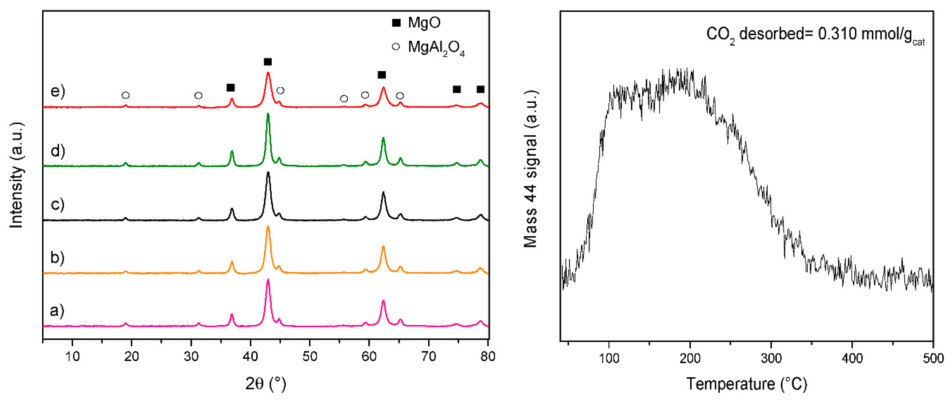
Figure 1. On the left, XRD patterns of the catalysts after calcination at 900 °C: (a) Mg/Al/O catalyst support, (b) 2NiRh C, (c) 3NiRh C, (d) 3NiRh IWI, (e) 3NiRh CP. On the right, CO2-TPD of the catalyst support. C: cluster; WI: wet impregnation; IWI: incipient wetness impregnation; CP: coprecipitation of a hydrotalcite-type precursor.
Catalysts 10 01345 g001
Figure 2. EDX profile analyses on two spots of the 5NiRh C catalyst.
Catalysts 10 01345 g002
Figure 3. H2-TPR profiles of the investigated catalysts: (a) 2NiRh C, (b) 3NiRh C, (c) 5NiRh C, (d) 3NiRh IWI, (e) 3NiRh CP.
Catalysts 10 01345 g003
Figure 4. HRTEM images of the investigated catalysts after H2-TPR analysis: (a) 3NiRh C, (b) 2NiRh C, (c,d) 3NiRh IWI.
Catalysts 10 01345 g004
Figure 5. CO2 (a) and CH4 (b) conversion values as a function of the reaction temperature and S/CH4 ratio values in the inlet stream. The red lines show the theoretical CH4 or CO2 conversion values calculated at the thermodynamic equilibrium.
Catalysts 10 01345 g005
Figure 6. Conversion of clean biogas for the different temperatures and S/CH4 values. The purple rectangles show the liters of clean biogas fed in each test condition.
Catalysts 10 01345 g006
Figure 7. HAADF and HRTEM images with particle size distribution and Ni, Rh content for the evidenced areas of the catalysts after reaction. (a) 2NiRh C, (b) 3NiRh C, (c) 5NiRh C.
Catalysts 10 01345 g007
Figure 8. HRTEM and HAADF images, particle size distribution and EDX analyses for different particles of the 3NiRh IWI catalyst after reaction.
Catalysts 10 01345 g008
Figure 9. Scheme of the experimental setup used for the evaluation of the catalysts. FC: flow controller; TI: temperature indicator; TC: temperature controller; PI: pressure indicator; PC: pressure controller.
Catalysts 10 01345 g009
Table 1. Specific surface area (SS) of the catalyst before and after reaction.
SSBET2NiRh C3NiRh C5NiRh C3NiRh IWI3NiRh CP
Before reaction (m2/g)7380486099
After reaction (m2/g)4339392646
Table 2. Comparison between the amount of biogas converted in this work (expressed as L h−1 gactive phase−1) and the results obtained for different Ni-based catalysts reported in literature.
Catalyst
Active Phase/Promoter/Support
GHSV
(mL h−1 g−1cat)
P
(Mpa)
T
(°C)
S/CH4
(v/v)
Biogas Converted
(L h−1 gactive phase−1)
Ref.
3NiRh C50,0000.59000.50926this work
8000.50686
7002.00172
Ni (10 wt %)/La2Zr2O720,0000.17001.0068[57]
Ni (10 wt %)/La2Zr2O760,0000.17001.0094[57]
Ni (10 wt %)/Al2O312,0000.17001.2017[38]
Ni (15 wt %)/MgO60,0000.78300.80181[58]
Ni (4 wt %)/
Rh2O3 (0.04 wt %)/γ-Al2O3
60000.17500.6776[59]
Ni (5 wt %)/γ-Al2O369,0000.18000.80731[60]
Ni (15 wt %)/
RuO2 (0.5 wt %)/HDL
120,0000.17500.14231[61]
Ni (10 wt %)/
Mo-carbide (0.5 wt %)/ZrO2
60,0000.18500.80308[62]
Table 3. Catalyst nomenclature, precursor, and respective metal loading. C: cluster; WI: wet impregnation; IWI: incipient wetness impregnation; CP: coprecipitation of a hydrotalcite-type precursor.
CatalystPrecursor/SynthesisNi (wt %)Rh (wt %)
2NiRh CNi10Rh(CO)19/WI2.00.3
3NiRh CNi10Rh(CO)19/WI3.00.5
5NiRh CNi10Rh(CO)19/WI5.00.9
3NiRh IWINi(NO3)2, Rh(NO3)3/IWI3.00.5
3NiRh CPNi(NO3)2, Rh(NO3)3/CP3.00.5
Mg/Al/O (support)Mg(NO3)2, Al(NO3)3/CP//
Table 4. Operative conditions used for the evaluation of the catalysts.
Temperature (°C)S/CH4 (v/v)P (MPa)GHSV (mL h−1 gcat−1)
9002.00.550,000
1.0
0.5
8002.0
1.0
0.5
7002.0
Publisher’s Note: MDPI stays neutral with regard to jurisdictional claims in published maps and institutional affiliations.