Congo Red Dye Degradation by Graphene Nanoplatelets/Doped Bismuth Ferrite Nanoparticle Hybrid Catalysts under Dark and Light Conditions


Abstract
:
1. Introduction
2. Characterization Details
3. Results
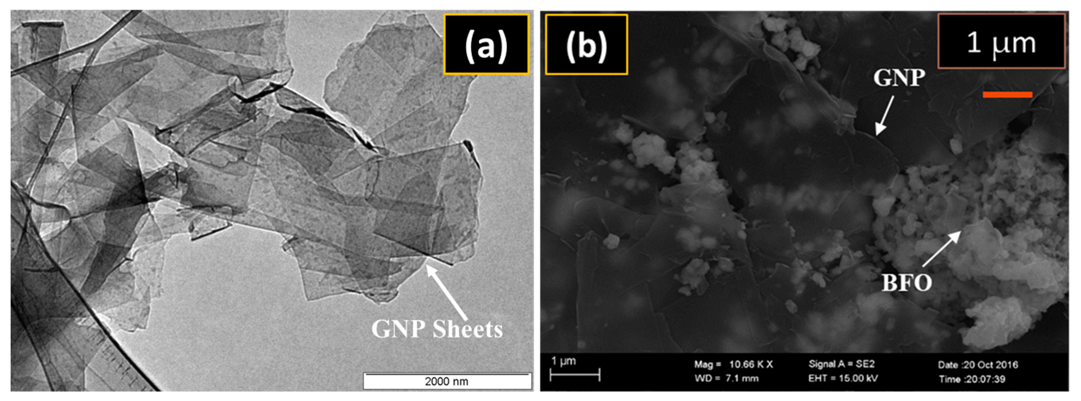
3.1. SEM Analysis
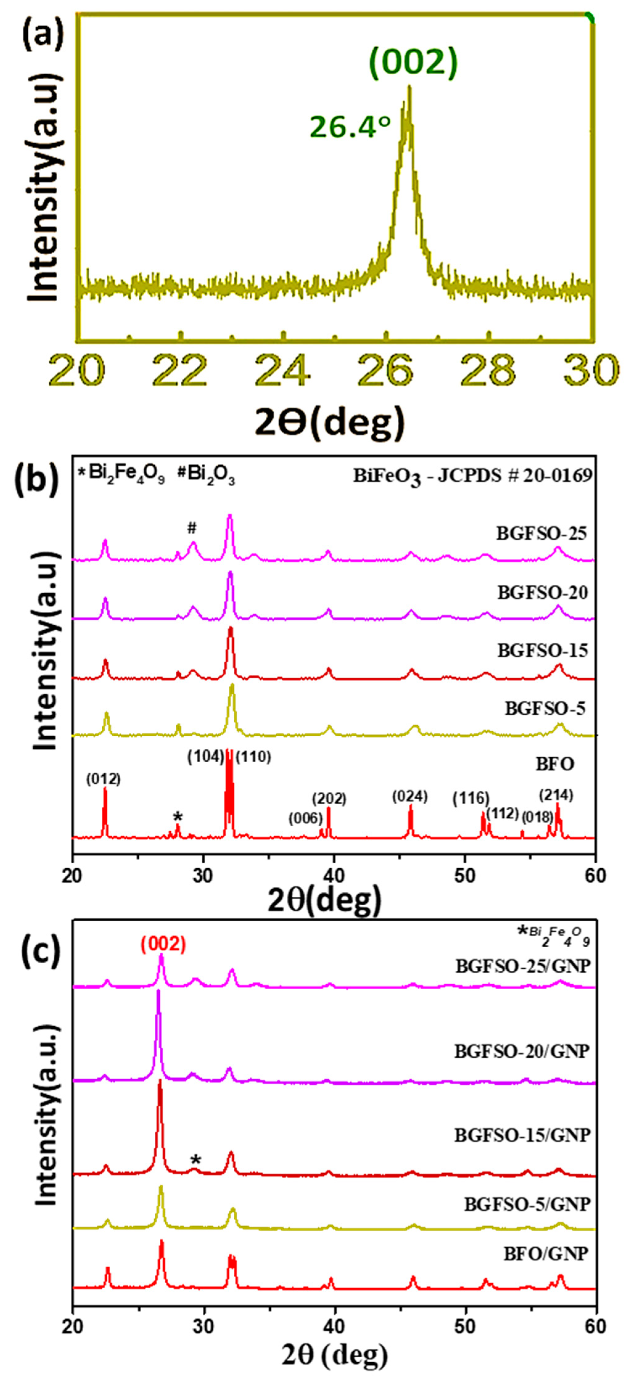
3.2. X-ray Photoelectron Spectroscopy (Elemental Analysis)
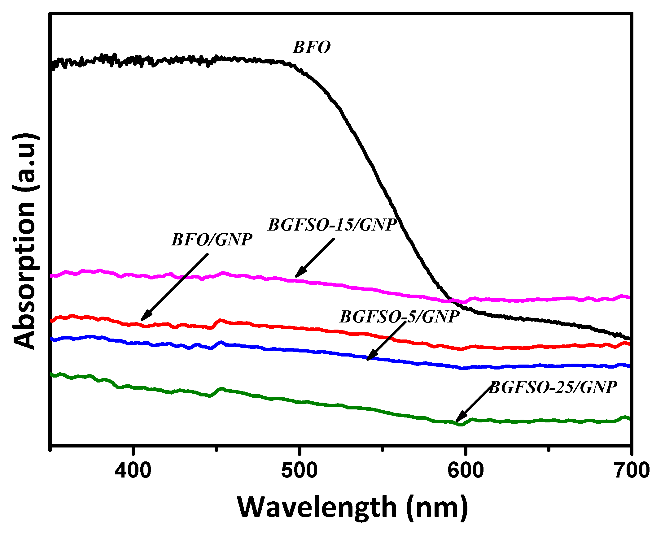
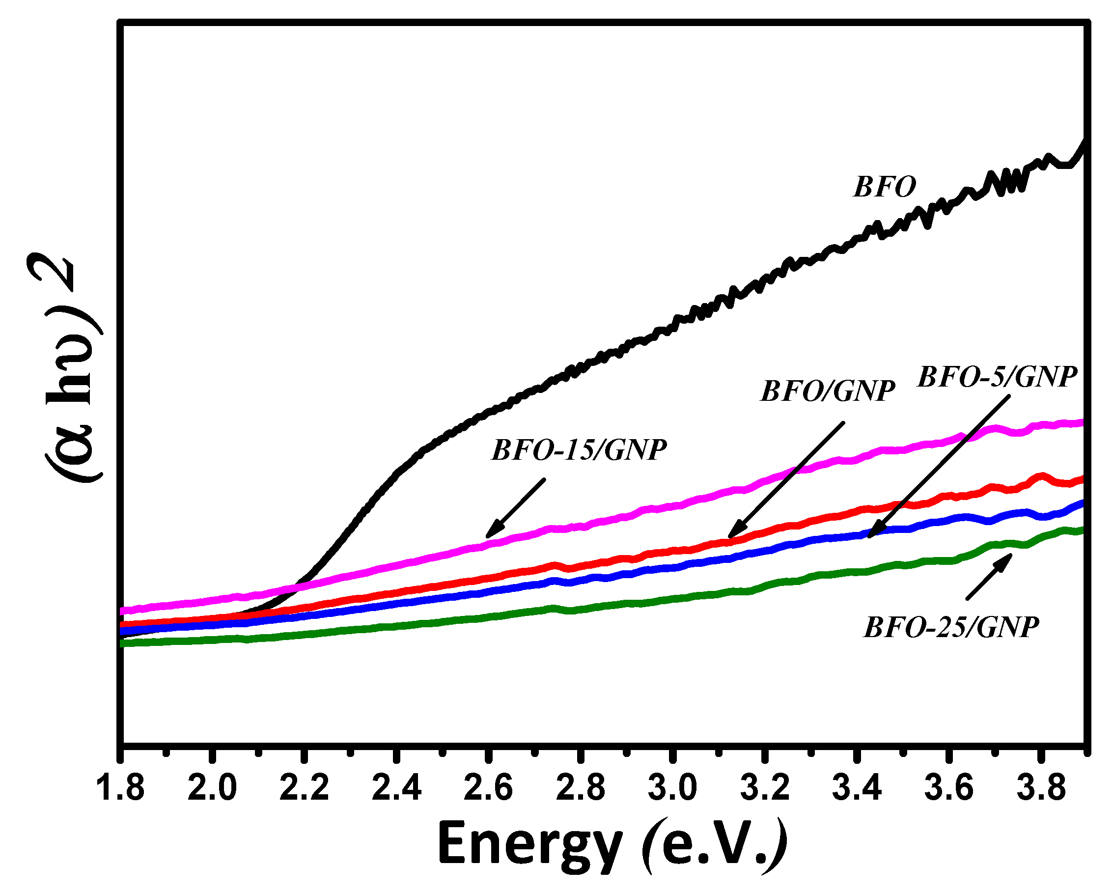
3.3. Absorption Analysis and Band-gap Calculations
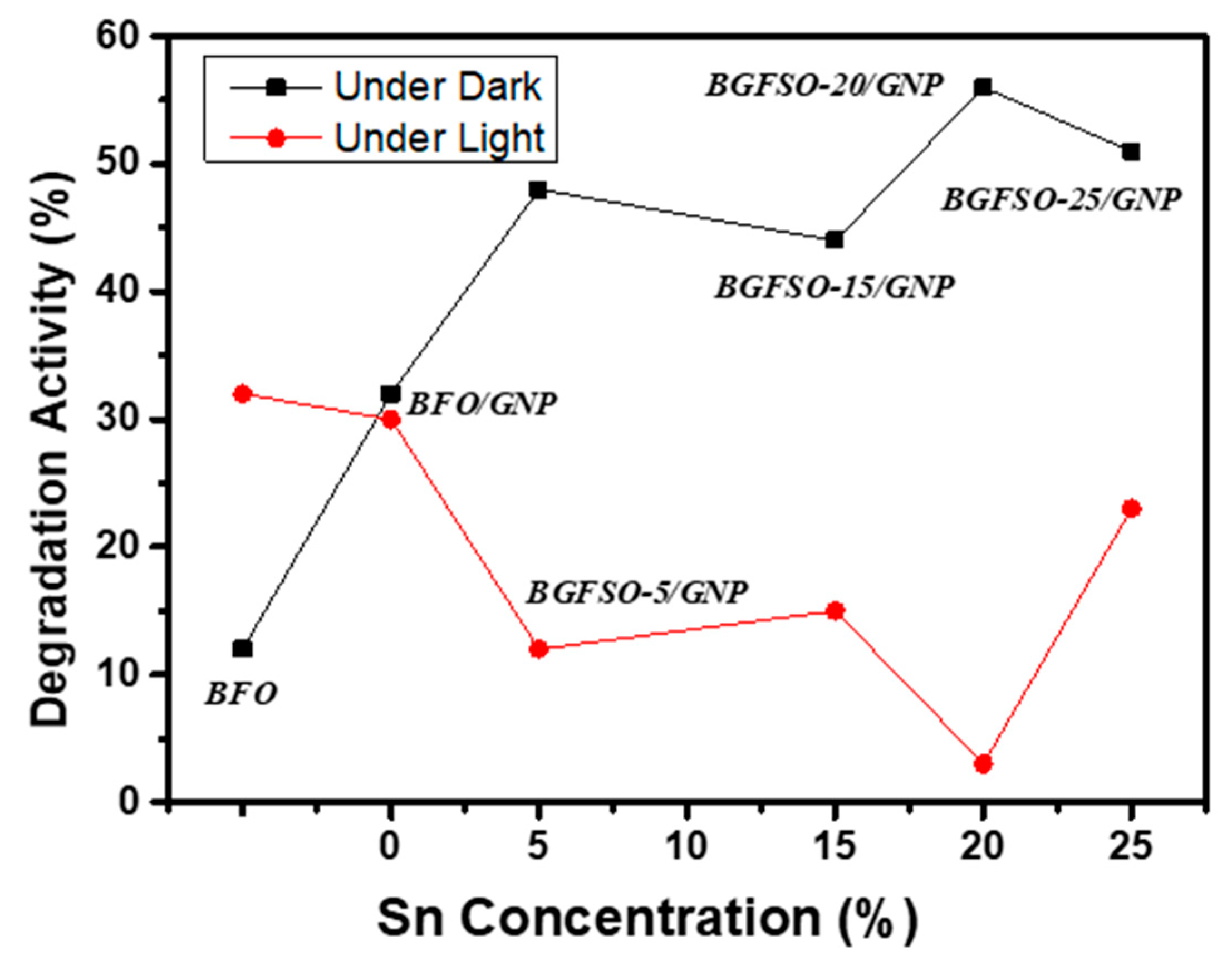
3.4. Photocatalytic Activity of Nanohybrids
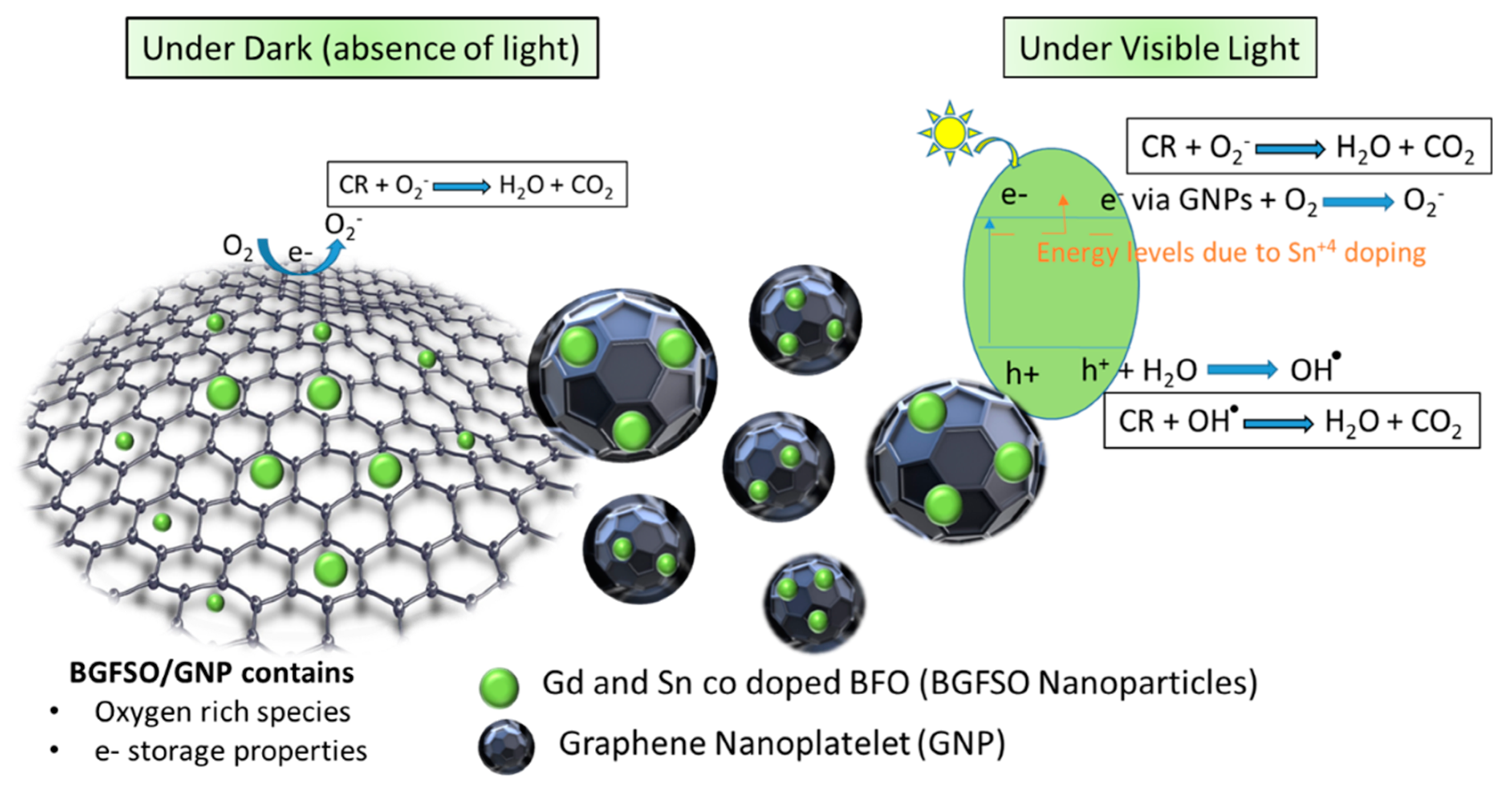
4. Dye Degradation Mechanism
5. Materials and Methods
5.1. Preparation of BGFSO Nanoparticles
5.2. Preparation of BGFSO-GNP Nanohybrids
6. Conclusion
Author Contributions
Funding
Acknowledgments
Conflicts of Interest
References
- Fujishima, A.; Zhang, X.; Tryk, D.A. TiO2 photocatalysis and related surface phenomena. J. Adv. Mater. 2018, 63, 515–582. [Google Scholar] [CrossRef]
- Rife, R.; Thomas, T.W.; Norberg, D.W.; Fournier, R.L.; Rinker, F.G.; Bonomoi, M.S. Chemical Demilitarization: Disposing of the Most Hazardous Wastes. Environ. Prog. 1989, 8, 167–175. [Google Scholar] [CrossRef]
- Xu, N.; Shi, Z.; Fan, Y.; Dong, J.; Shi, J.; Hu, M.Z.C. Effects of Particle Size of TiO2 on Photocatalytic Degradation of Methylene Blue in Aqueous Suspensions. Chem. Rev. 1999, 38, 373–379. [Google Scholar]
- Henderson, M.A. A surface science perspective on TiO2 photocatalysis. Surf. Sci. Rep. 2011, 66, 185–297. [Google Scholar] [CrossRef]
- Tada, H.; Hattori, A.; Tokihisa, Y.; Imai, K.; Tohge, N.; Ito, S. A Patterned-TiO2/SnO2 Bilayer Type Photocatalyst. J. Phys. Chem. B 2000, 104, 4585–4587. [Google Scholar] [CrossRef]
- Hoffmann, M.R.; Martin, S.T.; Choi, W.; Bahnemann, D.W. Environmental Applications of Semiconductor Photocatalysis. Chem. Rev. 1995, 95, 69–96. [Google Scholar] [CrossRef]
- Tan, Z.K.; Moghaddam, R.S.; Lai, M.L.; Docampo, P.; Highler, R.; Deschler, F.; Price, M.; Sadhanala, A.; Pazos, L.M.; Credgington, D.; et al. Bright light-emitting diodes based on organometal halide perovskite. Nat. Nanotechnol. 2014, 9, 687–692. [Google Scholar] [CrossRef]
- Hu, G.D.; Cheng, X.; Wu, W.B.; Yang, C.H. Effects of Gd substitution on structure and ferroelectric properties of BiFeO3 thin films prepared using metal organic decomposition. Appl. Phys. Lett. 2007, 91, 1–3. [Google Scholar] [CrossRef]
- Green, M.A.; Ho-Baillie, A.; Snaith, H.J. The emergence of perovskite solar cells. Nat. Photon 2014, 8, 506–514. [Google Scholar] [CrossRef]
- Sobhan, M.; Xu, Q.; Zhao, J.; Franklin, A.; Hu, Y.; Tse, J.S.; Wu, P. Modification of surface chemistry by lattice Sn dopingin BiFeO3 nanofibers. Europhys. Lett. 2015, 111, 1–5. [Google Scholar] [CrossRef]
- Schmid, H. Multi-ferroic magnetoelectrics. Ferroelectrics 1994, 162, 317–338. [Google Scholar] [CrossRef]
- Kube, F.; Schmid, H. Structure of a ferroelectric and ferroelastic monodomain crystal of the perovskite BiFeO3. Acta Crystallogr. 1990, B46, 698–702. [Google Scholar] [CrossRef] [Green Version]
- Yin, J.; Zou, Z.; Yee, J. Photophysical and Photocatalytic Activities of a Novel Photocatalyst BaZn1/3Nb2/3O3. J. Phys. Chem. B 2004, 108, 12790–12794. [Google Scholar] [CrossRef]
- Fatima, S.; Ali, S.I.; Iqbal, M.Z.; Rizwan, S. Facile The high photocatalytic activity and reduced band gap energy of La and Mn co-doped BiFeO3/graphene nanoplatelet (GNP) nanohybrids. RSC Adv. 2017, 7, 35928–35937. [Google Scholar] [CrossRef] [Green Version]
- Kanhere, P.; Chen, Z. A Review on Visible Light Active Perovskite-Based Photocatalysts. Molecules 2014, 19, 19995–20022. [Google Scholar] [CrossRef] [PubMed] [Green Version]
- Fatima, S.; Ali, S.I.; Younas, D.; Islam, A. Graphene nanohybrids for enhanced catalytic activity and large surface area. MRS Comm. 2018, 1, 27–36. [Google Scholar] [CrossRef] [Green Version]
- Tariq, A.; Irfan, S.; Akinwande, D.; Rizwan, S. Efficient Visible-Light Photocatalysis of 2D-MXene Nanohybrids with Gd3+- and Sn4+ -Codoped Bismuth Ferrite. ACS Omega 2018, 3, 13828–13836. [Google Scholar] [CrossRef] [Green Version]
- Umer, M.; Mahmood, N.; Awan, S.U.; Fatima, S.; Mahmood, A.; Rizwan, S. Rationally designed La and Se co-doped bismuth ferrites with controlled bandgap for visible light photocatalysis. RSC Adv. 2019, 30, 17148–17156. [Google Scholar] [CrossRef] [Green Version]
- Irfan, S.; Rizwan, S.; Shen, Y.; Tomovska, R.; Zulfiqar, S.; Sarwar, M.I.; Nan, C.W. Mesoporous template-free gyroid-like nanostructures based on La and Mn co-doped Bismuth ferrites with improved photocatalytic Activity. RSC Adv. 2016, 6, 114183–114189. [Google Scholar] [CrossRef]
- Wang, S.; Chen, D.; Niu, F.; Zhang, N.; Qin, L.; Huang, Y. Pd cocatalyst on Sm-doped BiFeO3 nanoparticles: Synergetic effect of a Pd co-catalyst and samarium doping on photocatalysis. RSC Adv. 2016, 6, 34574–34587. [Google Scholar] [CrossRef]
- Zhang, N.; Chen, D.; Niu, F.; Wang, S.; Qin, L.; Huang, Y. Enhanced visible light photocatalytic activity of Gd-doped BiFeO3 nanoparticles and mechanism insight. Sci. Rep. 2016, 6, 26467. [Google Scholar] [CrossRef] [PubMed]
- Guo, R.; Fang, L.; Dong, W.; Zheng, F.; Shen, M. Enhanced Photocatalytic Activity and Ferromagnetism in Gd Doped BiFeO3 Nanoparticles. J. Phys. Chem. C 2010, 114, 21390–21396. [Google Scholar] [CrossRef]
- Irfan, S.; Rizwan, S.; Shen, Y.; Li, L.; Asfandiyar; Butt, S.; Nan, C.W. The Gadolinium (Gd3+) and Tin (Sn4+) Co-doped BiFeO3 Nanoparticles as New Solar Light Active Photocatalys. Sci. Rep. 2017, 7, 42493. [Google Scholar] [CrossRef] [PubMed] [Green Version]
- Li, Z.; Shen, Y.; Yang, C.; Lei, Y.; Guan, Y.; Lin, Y.; Liu, D.; Nan, C.W. Significant enhancement in the visible light photocatalytic properties of BiFeO3-graphene nanohybrids. J. Mater. Chem. A 2012, 1, 823–829. [Google Scholar] [CrossRef]
- Li, T.; Shen, J.; Li, N.; Ye, M. Hydrothermal preparation, characterization and enhanced properties of reduced graphene-BiFeO3 nanocomposite. Mater. Lett. 2013, 91, 42–44. [Google Scholar] [CrossRef]
- Sun, A.; Chen, H.; Song, C.; Jiang, F.; Wang, X.; Fu, Y. Magnetic Bi25FeO40-graphene catalyst and its high visible-light photocatalytic performance. RSC Adv. 2013, 3, 4332–4340. [Google Scholar] [CrossRef]
- Soltani, T.; Lee, B.K. Sono-synthesis of nanocrystallized BiFeO3/reduced graphene oxide composites for visible photocatalytic degradation improvement of bisphenol A. Chem. Eng. J. 2016, 306, 204–213. [Google Scholar] [CrossRef]
- Reetu; Agarwal, A.; Sanghi, S.; Hooda, A. Rietveld analysis, dielectric and magnetic properties of Sr and Ti codoped BiFeO3 multiferroic. J. Appl. Phys. 2016, 110, 073909–073915. [Google Scholar]
- Yin, L.H.; Song, W.H.; Jiao, X.L.; Wu, W.B.; Zhu, X.B.; Yang, Z.R.; Dai, J.M.; Zhang, R.L.; Sun, Y.P. Multiferroic and magnetoelectric properties of Bi1−xBaxFe1−xMnxO3 system. J. Phys. D Appl. Phys. 2009, 42, 205402–205407. [Google Scholar] [CrossRef]
- Do, D.; Kim, J.W.; Kim, S.S. Effects of Dy and Mn co doping ferroelectric properties of BiFeO3 thin films. J. Am. Ceram. Soc. 2011, 94, 2792–2797. [Google Scholar] [CrossRef]
- KianI, M.; Kiani, A.B.; Khan, S.Z.; Rehmana, S.; Khan, Q.U.; Mahmood, I.; Saleemi, A.S.; Jalil, A.; Sohail, M.; Zhu, L. Facile synthesis of Gd and Sn co-doped BiFeO3 supported on nitrogen doped graphene for enhanced photocatalytic activity. J. Phys. Chem. Solids 2019, 130, 222–229. [Google Scholar] [CrossRef]
- Akhavan, O. Graphene Nanomesh by ZnO Nanorod Photocatalysts. ACS Nano 2010, 4, 4174–4180. [Google Scholar] [CrossRef] [PubMed]
- Novoselov, K.S.; Geim, A.K.; Morozov, S.V.; Jiang, D.; Katsnelson, M.I.; Grigorieva, I.V.; Dubonos, S.V.; Firsov, A.A. Two Dimensional Gas of Massless Dirac Fermions in Graphene. Nature 2005, 438, 197–200. [Google Scholar] [CrossRef] [PubMed]
- Sakamoto, J.; Heijst, J.V.; Lukin, O.; Schluter, A.D. TwoDimensional Polymers: Just a Dream of Synthetic Chemists. Angew. Chem. Int. Ed. 2009, 48, 1030–1069. [Google Scholar] [CrossRef]
- Doustkhah, E.; Ide, Y. Microporous layered silicates: Old but new microporous materials. New J. Chem. 2020, in press. [Google Scholar] [CrossRef]
- Xu, C.; Wang, X.; Zhu, J. Graphene-Metal Particle Nanocomposites. J. Phys. Chem. C 2008, 112, 19841–19845. [Google Scholar] [CrossRef]
- Rostamnia, S.; Doustkhah, E.; Karimi, Z.; Amini, S.; Luque, R. Surfactant-Exfoliated Highly Dispersive Pd-Supported Graphene Oxide Nanocomposite as a Catalyst for Aerobic Aqueous Oxidations of Alcohols. ChemCatChem 2015, 7, 1678–1683. [Google Scholar] [CrossRef]
- An, J.; Zhu, L.; Wang, N.; Song, Z.; Yang, Z.; Du, D.; Tang, H. Photo-Fenton like degradation of tetrabromobisphenol A with graphene BiFeO3 composite as a catalyst. Chem. Eng. J. 2013, 219, 225–237. [Google Scholar] [CrossRef]
- Nieto, A.; Lahiri, D.; Agarwal, A. Synthesis and properties of bulk graphene nanoplatelets consolidated by spark plasma sintering. Carbon 2012, 50, 4068–4077. [Google Scholar] [CrossRef]
- Kavan, L.; Yum, J.H.; Grtzell, M. Optically Transparent Cathode for Dye-Sensitized Solar Cells Based on Graphene Nanoplatelets. ACS Nano 2010, 5, 165–172. [Google Scholar] [CrossRef]
- Han, J.; Zhang, L.L.; Lee, S.; Oh, J.; Lee, K.S.; Potts, J.R.; Ji, J.; Zhao, X.; Ruoff, R.S.; Park, S. Generation of B-Doped Graphene Nanoplatelets Using a Solution Process and Their Supercapacitor Applications. ACS Nano 2012, 7, 19–26. [Google Scholar] [CrossRef] [PubMed]
- Arshad, A.; Iqbal, J.; Siddiq, M.; Mansoor, Q.; Ismail, M.; Mehmood, F.; Ajmal, M.; Abid, Z. Graphene nanoplatelets induced tailoring in photocatalytic activity and antibacterial characteristics of MgO/graphene nanoplatelets nanocomposites. ACS Omega 2019, 4, 8661–8668. [Google Scholar] [CrossRef]
- Lakshmi, V.; Rajagopalan, V. A New Synergetic Nanocomposite for Dye Degradation in Dark and Light. Sci. Rep. 2016, 6, 38606. [Google Scholar]
- Iqbal, M.A.; Irfan, S.; Amin, F.; Tariq, A.; Iqbal, M.Z.; Rizwan, S. La- and Mn-Codoped Bismuth Ferrite/Ti3C2 MXene Composites for Efficient Photocatalytic Degradation of Congo Red Dye. ACS Omega 2018, 4, 4053–4062. [Google Scholar] [CrossRef] [PubMed] [Green Version]
- Guerra, V.; Wan, C.; Degirmenci, V.; Solan, J.; Presvytis, D.; Watson, M.; McNally, T. Characterisation of graphite nanoplatelets (GNP) prepared at scale by high-pressure homogenisation. J. Mater. Chem. C 2019, 7, 6383–6390. [Google Scholar] [CrossRef]
- Batakliev, T.; Doycheva, I.P.; Angelov, V.; Georgiev, V.; Ivanov, E.; Kotsilkova, R.; Casa, M.; Cirillo, C.; Adami, R.; Sarno, M.; et al. Effects of Graphene Nanoplatelets and Multiwall Carbon Nanotubes on the Structure and Mechanical Properties of Poly(lactic acid) Composites: A Comparative Study. Appl. Sci. 2019, 9, 469. [Google Scholar] [CrossRef] [Green Version]
- Das, R.; Sarkar, T.; Mandal, K. Multiferroic properties of Ba2+ and Gd3+ co-doped bismuth ferrite: Magnetic, ferroelectric and impedance spectroscopic analysis. J. Phys. D Appl. Phys. 2012, 45, 455002. [Google Scholar] [CrossRef]
- Wang, F.; Drzal, L.T.; Qin, Y.; Huang, Z. Effects of functionalized graphene nanoplatelets on the morphology and properties of epoxy resins. High Perform. Polym. 2015, 28, 525–536. [Google Scholar] [CrossRef]
- Johra, F.T.; Lee, J.W.; Jung, W.G. Facile and safe graphene preparation on solution based platform. J. Ind. Eng. Chem. 2014, 20, 2882–2887. [Google Scholar] [CrossRef]
- Sun, R.; Yao, H.; Zhang, H.B.; Li, Y.; Mai, Y.W.; Yu, Z.Z. Decoration of defect-free graphene nanoplatelets with alumina for thermally conductive and electrically insulating epoxy composites. Compos. Sci. Technol. 2016, 137, 16–23. [Google Scholar] [CrossRef]
- Kubelka, P.; Munk, F. Ein Beitrag Zur Optik Der Farbanstriche. Tech. Phys. 1931, 12, 593–601. [Google Scholar]
- Irfan, S.; Liang, G.X.; Li, F.; Chen, Y.X.; Rizwan, S.; Jin, J.; Zhuanghao, Z.; Ping, F. Effect of Graphene Oxide Nano-Sheets on Structural, Morphological and Photocatalytic Activity of BiFeO3-Based Nanostructures. Nanomaterials 2019, 9, 1337. [Google Scholar] [CrossRef] [PubMed] [Green Version]
- Lightcap, I.V.; Kosel, T.H.; Kamat, P.V. Anchoring Semiconductor and Metal Nanoparticles on a 2-Dimensional Catalyst Mat. Storing and Shuttling Electrons with Reduced Graphene Oxide. Nano Lett. 2010, 10, 577–583. [Google Scholar] [CrossRef] [PubMed]


| Catalyst | Dye Removal Under Dark | Dye Removal Under Light | Total Catalytic Activity |
|---|---|---|---|
| BFO/GNP | 32% | 30% | 62% |
| BGFSO-5/GNP | 48% | 12% | 60% |
| BGFSO-15/GNP | 44% | 15% | 59% |
| BGFSO-20/GNP | 56% | 3% | 59% |
| BGFSO-25/GNP | 51% | 23% | 74% |
© 2020 by the authors. Licensee MDPI, Basel, Switzerland. This article is an open access article distributed under the terms and conditions of the Creative Commons Attribution (CC BY) license (http://creativecommons.org/licenses/by/4.0/).
Share and Cite
Fatima, S.; Ali, S.I.; Iqbal, M.Z.; Rizwan, S. Congo Red Dye Degradation by Graphene Nanoplatelets/Doped Bismuth Ferrite Nanoparticle Hybrid Catalysts under Dark and Light Conditions. Catalysts 2020, 10, 367. https://doi.org/10.3390/catal10040367
Fatima S, Ali SI, Iqbal MZ, Rizwan S. Congo Red Dye Degradation by Graphene Nanoplatelets/Doped Bismuth Ferrite Nanoparticle Hybrid Catalysts under Dark and Light Conditions. Catalysts. 2020; 10(4):367. https://doi.org/10.3390/catal10040367
Chicago/Turabian StyleFatima, Sabeen, S. Irfan Ali, Muhammad Z. Iqbal, and Syed Rizwan. 2020. "Congo Red Dye Degradation by Graphene Nanoplatelets/Doped Bismuth Ferrite Nanoparticle Hybrid Catalysts under Dark and Light Conditions" Catalysts 10, no. 4: 367. https://doi.org/10.3390/catal10040367