Abstract
This work reports on a modelling study of the influence of the distribution of metallic and acidic active centers within a catalytic fixed-bed reactor for the direct synthesis of dimethyl ether (DME), conducted to demonstrate the potential of reactor-level and pellet-level structuring of catalytic active centers in process integration and intensification. To account for the pellet structure, the analysis was performed with the aid of a heterogeneous model considering both interphase and intrapellet mass transport resistances. The study evaluated, in terms of DME and methanol yield and selectivity, the performance of a tubular reactor loaded with a physical mixture of monofunctional catalyst pellets or structured bifunctional catalyst pellets with different arrangements of the catalytic centers. It was confirmed that bifunctional catalysts overperform significantly a physical mixture of monofunctional particles. Moreover, it was shown that the internal structure of a bifunctional catalyst pellet is an important feature that deserves to be exploited deeper, in view of further intensification of the DME synthesis process to be achieved with a better reactor design.
1. Introduction
Dimethyl ether (DME) is considered a clean and economical alternative transportation fuel. Because of its high cetane number and relatively low self-ignition temperature, it can potentially replace diesel fuel in compression-ignition engines [1]. DME can be produced indirectly by methanol (MeOH) dehydration, or directly from syngas that, in turn, may be derived either from fossil fuels or from biomass [2]. Over the last two decades, much attention was paid to the development and improvement of the direct method, including, among the others, research on optimal catalysts selection and on their preparation methods [3,4]. The direct synthesis of DME, usually carried out in fixed-bed reactors, consists of a methanol synthesis step on a metallic catalyst followed by its dehydration on an acidic catalyst. A combination of these two types of catalytic active centers can be implemented either at the reactor level, through a physical mixture of metallic and acidic catalyst pellets [5], or by using bifunctional (hybrid) catalyst pellets integrating both types of catalytic active centers [3,4] that permit to improve the process performance by reducing mass transport resistances. The metallic function employed for the methanol synthesis step is usually composed of CuO, ZnO, and Al2O3 or Cr2O3 [1,6], whereas the acidic catalysts employed for methanol dehydration to DME are usually γ-Al2O3 or zeolites, e.g., H-ZSM-5, HY, or SAPO [1,6].
Conventionally, the bifunctional catalyst pellets are prepared by physical mixing and pelletizing of the two functionalities, which results in their uniform distributions within the pellet volume and close spatial integration. Although the very short distance between different sites is extremely beneficial since it permits to “remove” directly the intermediate product (in this case MeOH) by consecutive chemical reaction, core-shell configurations of the catalysts have recently been explored also for the synthesis of DME [4]. Such structured pellets, characterized by a Heaviside-like distribution of the functionalities within the pellet, are rather facile to prepare by employing physical coating techniques, and are expected to perform very well in terms of yield, selectivity, and stability. This is mainly due the fact that each step of the process takes place in favorable conditions, and the presence of H2O on metallic sites is limited. Moreover, when metallic sites are located in the pellet core, the methanol formed needs to pass through acidic shell before leaving the pellet [4].
The influence of the catalyst preparation method, the choice of active components, and the operating conditions onto the DME yield were studied in detail [3,5], however there are only a few experimental reports dealing with the impact of the distribution of active centers for MeOH and DME production, both at the reactor and at the single pellet level [4,5]. Most available theoretical studies dealing with mathematical modelling and simulation of tubular fixed-bed reactors for direct DME synthesis [7,8] also do not consider the distribution of the catalytic functionalities in a macroscale (reactor level) or in a microscale (pellet level) as an additional design parameter in performance augmentation. It is well-known that close integration of different functionalities, e.g., catalytic and adsorptive function in adsorptive reactors or two types of catalytic active sites in catalytic reactors integrating multistep chemical processes, represents a well-established method for process intensification [9]. However, to the authors’ knowledge this approach has not been exploited thus far in the process of DME synthesis.
For this reason, in this work a simulation-based analysis of the possibility of enhancement of the direct synthesis of dimethyl ether from syngas by proper structuring of the catalytic bed, both on the reactor and on the pellet level (considering uniform vs. core-shell arrangements of the catalytic sites), was performed with the aid of an isothermal heterogeneous mathematical model of a fixed-bed catalytic reactor operating under steady-state conditions. A previous study [10] demonstrated a very strong influence of the internal pellet structure and its size on the DME yield and selectivity, based on a single pellet behavior and limited to constant bulk gas conditions. Here the analysis is extended to the entire reactor, and the performance indices are evaluated globally with reference to the product stream at the reactor outlet.
2. Results and Discussion
A scheme with the following chemical reactions was considered to describe the direct synthesis of DME from syngas via methanol [1] in a fixed-bed reactor:
- Hydrogenation of CO:
- Reverse water-gas shift reaction:
- Hydrogenation of CO2:
- Dehydration of methanol to DME:
To reduce the model complexity, it was assumed that the ideal gas law is obeyed. The main aim of the analysis was to evaluate the influence of intrapellet and gas–solid mass transfer on the DME yield and relevant reaction selectivity achieved for various arrangements of metallic (CuO/ZnO/Al2O3) and acidic (γ-Al2O3) active centers within the bed. To this aim, the catalyst pellet submodel, combined with the flowing gas model, accounts both for multicomponent mass diffusion and intrapellet species concentration profiles. Details concerning the kinetic model employed, the formulation of the catalyst pellet submodel and the flowing gas model, as well as the description of the numerical methods employed, are given in Section 3.1, Section 3.2, Section 3.3, Section 3.4.
Several variants of catalytic bed arrangements and pellet structures, illustrated in Figure 1, were analyzed numerically, namely:
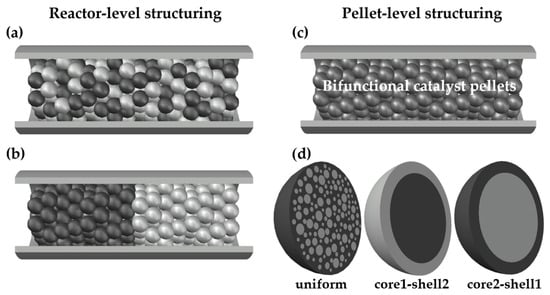
Figure 1.
Structuring of catalytic activities at reactor level and at pellet level: (a) A physical mixture of monofunctional methanol (MeOH) and dimethyl ether (DME) catalyst pellets; (b) a layered distribution of monofunctional MeOH and DME catalyst pellets; (c) a fixed-bed made of bifunctional catalyst pellets; (d) bifunctional catalyst pellets with uniform, core1-shell2 and core2-shell1 distribution of two types of catalytic active sites.
- A physical mixture of two types (MeOH and DME) monofunctional catalyst pellets (Figure 1a);
- A layered distribution of monofunctional pellets with the MeOH catalyst pellets located in the first section of the reactor (Figure 1b);
- A bed made of bifunctional pellets characterized by uniform distribution of MeOH and DME catalytic active centers (Figure 1c,d; note that the structure shown in the left-hand side of Figure 1d shows schematically uniform distribution of two types of catalysts in the entire volume of the pellet with dark-gray zone corresponding to MeOH catalyst and light-gray spheres corresponding to DME catalyst);
- A bed made of bifunctional pellets characterized by core-shell distribution (Figure 1c,d), where core1-shell2 arrangement concerns the pellet with MeOH and DME active centers distributed, respectively, in the pellet core and shell, while core2-shell1 denotes reverse arrangement of two type of active centers within the pellet.
The overall ratio of the solid volume occupied by MeOH and DME catalytic active centers was kept equal to 1:1 across the study. For structured core-shell pellets, with active sites uniformly distributed in number density throughout the pellet, to keep the ratio of MeOH and DME catalyst equal to 1:1, the core radius was set to 0.7937·Rp, where Rp is the pellet radius. Table 1 reports the values of the basic parameters used in the numerical simulations, selected following References [4,5,6,11,12].

Table 1.
Main values of the model parameters employed in numerical simulations [4,5,6,11,12].
One of the main factors that may influence the performance of differently structured catalytic fixed-bed reactors, operated with mono- or bifunctional pellets, is the radius of the catalyst pellet. Thus, to evaluate the influence of different arrangements within the bed of catalytic active centers for MeOH synthesis and for DME production, the model equations were solved for the five variants of the catalyst bed structures mentioned above, for the pellet radius in the range of Rp = 0.5–2.5 mm. Moreover, the influence of the gas bulk velocity on the DME yield and reaction selectivity indices was analyzed. Indeed, the gas bulk velocity affects not only the gas residence time in the reactor, but also the mass transfer between the bulk and the particle surface.
Figure 2 reports the molar fractions of methanol (Figure 2a) and DME (Figure 2b) along the reactor, obtained for Rp = 1.5 mm and superficial gas velocity at the reactor inlet uin = 0.05 m·s−1. The abbreviations used in Figure 2 make reference to the reactor loading (Figure 1) and denote, respectively: bif. uni—bifunctional pellets with uniform distribution of MeOH and DME active centers; bif. c1-s2—bifunctional pellets with MeOH catalyst located in the core and DME catalyst located in the pellet shell; bif. c2-s1—bifunctional pellets with reverse arrangement of active centers with respect to bif. c1-s2. (Figure 1c,d); mono. uni.—a uniform mixture of monofunctional MeOH and DME catalyst pellets (Figure 1a); mono. lay.—a layered distribution of monofunctional pellets with the MeOH catalyst pellets located in the first section of the reactor (Figure 1b).
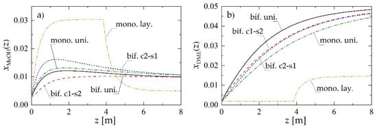
Figure 2.
Molar fraction profiles along the reactor obtained using different reactor- and pellet-level structuring of catalytic active sites for Rp = 1.5 mm and uin = 0.05 m·s−1: (a) MeOH molar fraction; (b) DME molar fraction.
The layered distribution of monofunctional catalyst pellets results in the lowest predicted molar fraction of DME in the product stream (mono. lay. in Figure 2b). Comparison of the other arrangements of the active sites, both at the pellet and at the reactor level, reveals that the closer the integration of the functionalities in the direct synthesis of DME, the higher its molar fraction in the product stream (Figure 2b). Hence, for the chosen values of the parameters, a bifunctional catalyst with uniform distribution of two types of active centers (bif. uni.) performs slightly better than both structured bifunctional pellets (bif. c1-s2 and bif. c2-s1), which in turn overperform a physical mixture of monofunctional pellets (mono. uni.).
To illustrate the mechanism through which the structure of the bifunctional pellet influences the process performance, Figure 3 presents selected radial profiles of MeOH and DME molar fractions within the pellet obtained for Rp = 1.5 mm and uin = 0.05 m·s−1. Figure 3a,c shows the distribution of reactants within the pellet located near the reactor inlet, i.e., at z = 0.5 m, whereas Figure 3b,d illustrates the pellet behavior at the reactor outlet (z = 8 m).
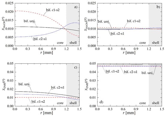
Figure 3.
Molar fraction radial profiles within bifunctional catalyst pellet for Rp = 1.5 mm and uin = 0.05 m·s−1: (a) MeOH molar fraction at a distance of z = 0.5 m from the reactor inlet; (b) MeOH molar fraction at the reactor outlet; (c) DME molar fraction at a distance of z = 0.5 m from the reactor inlet; (d) DME molar fraction at the reactor outlet.
Regardless of the location along the reactor, the pellet of the c1-s2 type presents the highest molar fraction of methanol (Figure 3a,b) in the inner core, where MeOH is synthesized from carbon oxides and hydrogen on metallic sites. For the core1-shell2 structure of the bifunctional pellet, dehydrogenation of MeOH into DME requires its diffusion through pores to the outer shell containing acidic catalysts: transformation of the methanol into DME manifests there (Figure 3a,b) by a significant drop in the MeOH concentration. Bifunctional catalyst pellets with c2-s1 arrangement of active centers exhibit the reverse behavior. Since in this case the metallic catalyst is located in the pellet shell, the internal mass transport resistance does not influence so strongly the MeOH synthesis step, which is visible above all in the initial section of the reactor (Figure 2a). For the smallest distance between active sites of different types provided by bif. uni. pellet, the intermediate product, i.e., methanol, is directly transformed in the consecutive reaction to DME in the entire volume of the pellet which results in monotonic concentration profiles (Figure 3).
To understand better the mechanism of the process taking place within structured bifunctional pellets, molar fraction profiles of H2O corresponding to the case analyzed above are shown in Figure 4. According to Le Chatelier principle, high content of water limits the production of methanol that occurs via hydrogenation of CO2. At the same time the dehydration reaction contributes to the production of H2O. If the reaction zones are divided, through the core-shell structure, the presence of H2O on metallic sites can be significantly limited. This effect is particularly visible for the pellet located near the reactor inlet, i.e., at z = 0.5 m (Figure 4a).
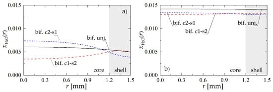
Figure 4.
Molar fraction radial profiles within bifunctional catalyst pellet for Rp = 1.5 mm and uin = 0.05 m·s−1: (a) H2O molar fraction at a distance of z = 0.5 m from the reactor inlet; (b) H2O molar fraction at the reactor outlet.
Figure 5 shows a comparison of molar fraction profiles of MeOH and DME obtained using bifunctional catalyst pellets with uniform distribution of catalysts (bif. uni.), and monofunctional MeOH and DME catalyst pellets mixed uniformly in the reactor (mono. uni., where mono. uni. MeOH pellet and mono. uni. DME pellet denote, respectively, catalyst pellets with metallic and acidic active centers only). The conclusion that can be drawn from the analysis of Figure 5 is that direct local “removal” (via dehydration) of methanol in the bifunctional catalyst pellet is definitely more efficient, because of the much higher concentration of MeOH on acidic active centers in bifunctional (Figure 5a, solid line) than in monofunctional pellets (Figure 5a, long-dashed line) for DME synthesis. The average value of MeOH molar fraction in the bifunctional pellet is about 0.131, whereas for the monofunctional DME pellet it is only 0.059. Thus, despite the smaller number of acidic active centers in the bifunctional pellet, the rate of dehydration of MeOH to DME is still higher than in monofunctional pellet.
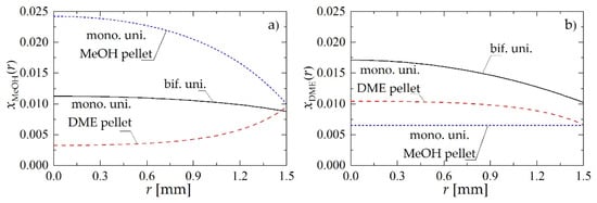
Figure 5.
Molar fraction profiles within a bifunctional catalyst pellet with uniform distribution of catalytic sites, and monofunctional MeOH and DME catalyst pellets mixed uniformly in the reactor for Rp = 1.5 mm and uin = 0.05 m·s−1 at a distance of z = 0.5 m: (a) MeOH molar fraction; (b) DME molar fraction.
To globally evaluate the influence of the arrangement of the catalysts within the pellet (or bed) on the reactor performance, the following indices were defined and calculated based on the numerical simulation results [4,13]:
- Yield of DME or MeOH:
- Product (i.e., DME or MeOH) selectivity:
In the above definitions Fi,in and Fi,out are, respectively, the molar flowrates of component i (where i = DME or MeOH) in the feed and in the product stream. Subscript COx refers to CO + CO2, while ni is the number of carbon atoms in component i. In the definition of selectivity given by Equation (6) the summation in the denominator is made over organic products only, i.e., DME and MeOH.
Figure 6a,b shows the effect of pellet radius, Rp, and superficial gas velocity at the reactor inlet, uin, on YDME. For all values of Rp and uin, the performance of the reactor with layered distribution of monofunctional pellets (mono. lay., denoted with ★) significantly deviates from the other catalyst arrangements within the bed, whereas a bifunctional catalyst pellet with uniform distribution of the active centers (bif. uni., denoted with ■) always performs best.
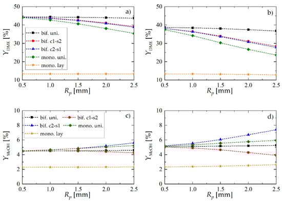
Figure 6.
Yield of dimethyl ether and methanol obtained using different reactor- and pellet-level structuring of catalytic active sites: (a) yield of DME for uin = 0.05 m·s−1; (b) yield of DME for uin = 0.1 m·s−1; (c) yield of MeOH for uin = 0.05 m·s−1; (d) yield of MeOH for uin = 0.1 m·s−1.
Structured core-shell bifunctional catalyst pellets behavior is also noteworthy. Here, the values of DME yield may suggest that the arrangement of metallic and acidic catalytic functionalities within the pellet of core-shell type (e.g., metallic in the core and acidic in the shell i.e., c1-s2, or vice versa i.e., c2-s1) does not influence the process performance. The analysis of methanol yield (Figure 6c,d) and selectivity toward DME and MeOH (Figure 7) confirm the superiority of c1-s2 over c2-s1 pellets. As it can be observed in Figure 6c,d, for the c2-s1 arrangement of catalytic active sites the amount of unconverted methanol in the product stream appears to increase with increasing pellet radius, while the reverse occurs for the s1-c2 arrangement i.e., with metallic sites located in the pellet core. The superiority of bif. c1-s2 over bif. c2-s1 can be explained by noting that in bif. c2-s1 there are two “sinks” of methanol—it can either diffuse toward the core where it is dehydrated on acidic active sites, or it can diffuse toward the surface from where it is transported into the gas bulk via convective gas flow. In contrast, for bif. c1-s2 methanol is synthesized in the pellet core and has to diffuse first through the shell containing acidic sites, where it is partially dehydrated, and the remaining part is transported into the gas bulk. Thus, we can speak here about only one “sink” of methanol, which in turn shifts the reaction toward lower MeOH and higher DME yield.
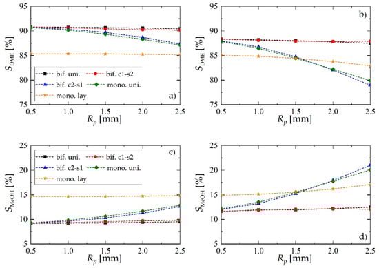
Figure 7.
Selectivity of dimethyl ether and methanol obtained using different reactor- and pellet-level structuring of catalytic active sites: (a) selectivity of DME for uin = 0.05 m·s−1; (b) selectivity of DME for uin = 0.1 m·s−1; (c) selectivity of MeOH for uin = 0.05 m·s−1; (d) selectivity of MeOH for uin = 0.1 m·s−1.
The superiority of the c1-s2 bifunctional pellet is also confirmed by the values of selectivity achieved toward the intermediate product (MeOH) and the final product (DME), reported in Figure 7. For lower values of the gas velocity (Figure 7a,c) the performance, in terms of selectivity, of bifunctional c2-s1 pellets is comparable with the performance of the reactor loaded with a physical mixture of two types of catalyst pellets (mono. uni.), and it falls significantly when the pellet radius gets larger. This effect is accompanied by increasing selectivity toward methanol (Figure 7c). On the other hand, the performance of bifunctional c1-s2 pellet is practically the same as the performance of bifunctional pellets with uniformly distributed catalytic sites (bif. uni., Figure 7a,c). For higher gas flow velocities (Figure 7b,d) the differences between different arrangements become even more evident. Interestingly, the bifunctional c2-s1 pellet appears to perform worst. For larger values of Rp, bif. c1-s2 tends to over perform slightly bif. uni.
Regardless of the bed configuration, increasing of the inlet gas velocity results in lower values of DME yield and selectivity, and higher values of these performance indices for MeOH (Figure 6 and Figure 7). This is an obvious effect of the shorter contact time. Analysis of the DME and MeOH yield (Figure 6) reveals that DME yield is more influenced by the gas velocity than the MeOH yield. MeOH is characterized by higher values of transport properties than DME: increasing gas velocity enhances interphase mass transfer, and the unconverted methanol is easily transported into the gas bulk.
We recall that, in all of the cases described above, the overall ratio of the solid volume occupied by MeOH and DME catalytic active centers was set to 1:1. Particularly, for the case of bifunctional catalyst pellets characterized by uniform distribution of MeOH and DME catalytic active centers, the volume fraction of the pellet occupied by MeOH sites is f1 = 0.5 and the volume fraction of the pellet occupied by DME sites is f2 = 0.5. For the core-shell arrangement, both f1 and f2 are step functions of the pellet radial coordinate r. To investigate the importance of f1 and f2 = 1 − f1 as additional design parameters, further simulations were performed for bifunctional catalyst pellets both with uniform and c1-s2 distribution of active sites with various values of v1, defined as the volume fraction of the pellet occupied by metallic active centers:
Figure 8 shows the results, reported in terms of products yield (MeOH, DME) and relevant selectivities, as a function of v1, confirming that, for the values of the operating parameters here analyzed, 1:1 is the best choice. Acceptable performance is conserved within a rather wide neighborhood of v1 = v2 = 0.5, which in case of uniform radial distribution of catalytic sites is equivalent to f1 = f2 = 0.5.
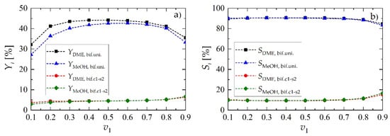
Figure 8.
Yield and selectivity of methanol and dimethyl ether for bifunctional pellets as a function of the volume fraction occupied by metallic sites, v1, for Rp = 1.5 mm and uin = 0.05 m·s−1: (a) yield of DME and MeOH; (b) selectivity toward DME and MeOH.
3. Materials and Methods
This investigation is conducted with the aid of a mathematical model describing the mechanisms of mass convection and diffusive mass transfer, as well as the chemical kinetics of catalytic reactions (Section 3.1). The tubular reactor is modelled as isothermal, hence no heat transfer needs to be considered, and heterogeneous, hence a solid-phase (Section 3.2) and a gas-phase (Section 3.3) are separately described. It should be underlined that, because of the globally exothermic character of the process, isothermal conditions are not generally found. Nevertheless, since the process is typically run in cooled pipe-shell reactors, very often referred to as isothermal reactors, and given the rather high content of an inert in the feed (Table 1), as demonstrated in [8] no substantial temperature gradients are expected. The pressure drop along the bed, across the film next to the pellet surface, and within the pellet pores is neglected in this model. Particularly, velocity changes because of molar changes between reactants and products are by far more important than velocity changes because of pressure gradients. Additionally, the pressure drop estimated via the Ergun law is at most 2% of the average process pressure.
Other assumptions of the model are:
- The contribution of axial and radial mass dispersion is neglected, and the gas flow is modelled as one-dimensional along the reactor;
- The gas mixture density is determined based on the ideal gas law;
- The pellet is spherical and symmetric, which results in one-dimensional description of species concentrations along the pellet radius;
- A uniform pore model is employed to describe the pellet structure;
- The intrapellet mass diffusion fluxes are described according to the Wilke-Bosanquet model accounting both for molecular and Knudsen diffusion;
- The boundary conditions imposed at the pellet surface account for the resistance to mass transfer between the bulk gas and the pellet surface.
The above assumptions are a reasonable compromise in terms of model complexity and accuracy, and a plain finite-difference numerical approximation (Section 3.4 and Appendix C) delivers results in reasonable computational time, so that the parameter space can be satisfactorily explored without adopting complex model reduction approaches. The resulting code permits to test the influence of exploiting the degrees of freedom in the spatial distribution of active functionalities of the catalysts onto the reactor performance for the chemical reactions considered, for a selected set of values of the operation parameters.
3.1. Chemical Kinetics
In the present study, to describe the kinetics of the process, the following kinetic model of methanol synthesis step over CuO/ZnO/Al2O3 (in wt%: CuO 50-60, ZnO 21-25, Al2O3 15-28) [14,15] (Equations (8)–(10)) and its dehydration over γ-Al2O3 [16] (Equation (11)) were used:
with r1 being the rate of hydrogenation of CO (Equation (1)), r2—the rate of reverse water-shift reaction (Equation (2)), r3—the rate of hydrogenation of CO2 (Equation (3)), and r4—the rate dehydration of methanol to DME (Equation (4)).
The values of the kinetic parameters and adsorption equilibrium constants in Equations (8)–(10) describing methanol synthesis from syngas are calculated following Ref. [14]:
whereas the constants for the dehydration step taking place on the acidic active sites (Equation (11)) are calculated as [9]:
The temperature-dependent equilibrium constants for both steps are determined from the polynomial formulas given in [17,18] and reported in Appendix A.
3.2. Catalyst Pellet Submodel
Assuming spherical symmetry of the catalyst pellet and constant pressure, thus neglecting viscous flow within the pellet, the steady-state mass balance and diffusive flux equations for species are [11,12]:
with f1 and f2 being, respectively, the pellet volume fractions occupied by metallic (MeOH) and acidic (DME) catalytic active centers.
For a bifunctional catalyst with uniform distribution of two types of catalysts, f1 = f2 = 0.5, whereas for monofunctional catalyst pellets f1 = 1 and f2 = 0 for the MeOH catalyst pellet, and f1 = 0 and f2 = 1 for the DME catalyst pellet. For structured core-shell pellets, to keep the ratio of MeOH and DME catalyst equal to 1:1, the core radius is set to 0.7937·Rp, where Rp is the pellet radius, thus both f1 and f2 are unit step functions of r (Figure 1d).
The boundary conditions associated with the mass balance and flux Equations (17) and (18) are:
with the mass transfer coefficients, ki,m, calculated from the Sherwood number correlation for fixed bed [19]:
Concentration-dependent effective diffusion coefficients, Di,eff, are determined according to the Wilke-Bosanquet model of multicomponent mass diffusion [20]:
with binary diffusion coefficients, , based on the Chapman-Enskog kinetic theory [21] (Appendix B).
3.3. Gas-Phase Model
Under the assumption of ideal one-dimensional gas flow, where the gas velocity , the mass and continuity balance equations for a reactor loaded with multifunctional catalyst pellets can be written, respectively, as:
The first term on the left-hand side of Equation (25) describes the convective gas transport in the z direction, whereas the second term represents the gas-to-solid mass transport with being the external surface area to volume ratio of the spherical catalyst pellet. The overall mass balance of the flowing gas given by Equation (26) is obtained by summation of the component mass balances (Equation (25)) over all K components.
For a reactor loaded with a physical mixture of monofunctional DME and MeOH catalyst pellets, the balance equations become:
As can be observed in Equations (27) and (28), for the reactor loaded with monofunctional pellets two contributions are distinguished in the term describing the gas-to-solid mass transport, computed according to the volume fraction of DME and MeOH catalyst pellets at each location along the reactor.
The boundary conditions at the reactor inlet associated with Equations (25)–(28) are:
3.4. Numerical Methods
The two-scale mathematical model of a catalytic fixed-bed reactor for the direct synthesis of DME formulated in the above sections, consisting of a gas-phase model coupled with a single pellet submodel, was transformed into a system of non-linear algebraic equations using a finite difference method. For the catalyst pellet, the derivatives of the diffusive fluxes were approximated at N = 51 discrete nodes equally spaced along the pellet radius, using the second-order scheme proposed in [22] (Appendix C). The reactor length was discretized using M = 101 nodes and the standard backward difference (upwind) was used to approximate the spatial derivatives present in the gas bulk equations. The resulting system of algebraic equations was resolved in MATLAB using the fsolve function. Note that, for the reactor loaded with a physical mixture of monofunctional catalyst pellets, two pellet equations need to be solved at each node along the reactor length. Considering a gas mixture (Table 1) composed of eight species, i.e., six reactants and two inert gases (N2, CH4), and given that the concentration of one component can be calculated by difference, the problem comes to the numerical solution of 7 × N algebraic equations for the solid phase and eight algebraic equations (mass balances and continuity equation) for the gas phase at each discretization node along the reactor. Thus, for the reactor loaded with bifunctional pellets and for the layered distribution of monofunctional pellets, the total number of equations to be solved is (7 × N + 8) × M = 36,865, whereas for the uniformly mixed monofunctional pellets it is: (2 × 7 × N + 8) × M = 72,922.
In the case of insignificant mass transport resistances, the boundary conditions given by Equation (21) might be replaced with Dirichlet boundary at the pellet surface, i.e., , however, given the distributed-parameter character of the catalyst pellet submodel employed in this study, such a simplification would not bring substantial saving in the computational costs. For instance, in the reactor loaded with bifunctional pellets it would lead to reduction in the total number of equations from 36,865 to 36,057.
4. Conclusions
A mathematical modelling study of a fixed-bed catalytic reactor for the direct synthesis of dimethyl ether from synthesis gas via methanol was performed to demonstrate the potential of manipulating the process performance by macro- and microstructuring of the catalytic bed. Particular attention was paid to the influence of the combination of metallic and acidic active centers on a single, bifunctional catalyst pellet. Because of reduced distances between two types of catalytic activities, bifunctional pellets overperform, in terms of DME yield, physical mixtures of monofunctional pellets, especially for larger pellet diameters. For structured core-shell particles, it was shown that the DME yield is affected by internal and external mass transport: namely, it is lower than that for the bed loaded with bifunctional pellets with uniform distributions of two types of catalysts. Nevertheless, under properly selected process conditions, a structured pellet with metallic and acidic active centers located, respectively, in the pellet core and shell, is worth considering. In fact, for higher flow velocities and larger radii, structured pellets with active sites for methanol synthesis located in the core give higher values of selectivity toward the final product than the pellets with uniform distributions of metallic and acidic functionalities.
Given the promising results presented within this study, and the fact that a proper structuring of the catalyst pellets and multifunctional catalytic reactors is one of the most “elegant” way of optimizing such objects, the problem needs further studies, focused particularly on optimal pellet and reactor design. Of course, a rigorous treatment of the catalyst pellet in the model-based reactor design will be needed, requiring the use of a two-scale heterogeneous model accounting both for transport processes on the reactor scale and intrapellet transport phenomena. In this view, optimal design results in great challenges regarding the computational effort, requiring repeated computations of solutions of the two-scale model as the decision variable values are explored. Therefore, to address such a problem in an efficient manner, it will be also necessary to develop a specifically efficient computational methodology.
Author Contributions
Conceptualization, K.B. and G.C.; methodology, K.B. and G.C.; software, K.B. and K.S.-M.; validation, K.B. and K.S.-M.; formal analysis, K.B.; investigation, K.B.; data curation, K.B.; writing—original draft preparation, K.B.; writing—review and editing, K.B. and G.C.; visualization, K.B. and K.S.-M.; funding acquisition, K.B. All authors have read and agreed to the published version of the manuscript.
Funding
The research was financed by the Polish National Science Centre, project number 2017/26/D/ST8/00509.
Acknowledgments
G.C. is grateful to Università del Sannio for granting a sabbatical leave that made this and other research works possible.
Conflicts of Interest
The authors declare no conflict of interest.
Nomenclature
| C | Total concentration, kmol·m−3 |
| Ci | Concentration of component i, kmol·m−3 |
| dpore | Pore diameter, m |
| dr | Reactor diameter, m |
| Deff | Effective diffusion coefficient, m2·s−1 |
| Di,K | Knudsen diffusion coefficient for component i, m2·s−1 |
| Di,W | Wilke diffusion coefficient for component i, m2·s−1 |
| Binary diffusion coefficient, m2·s−1 | |
| fj | Local volume fraction of the catalyst pellet with active sites enhancing jth step of the process |
| Fi | Molar flow rate of component i, kmol·s−1 |
| Ji | Molecular diffusion flux, kmol·s−1·m−2 |
| kj | Reaction rate constant, kmol·s−1·kg−1·bar−1 or kmol·s−1·kg−1·bar−1/2 |
| km | Mass transfer coefficient, m·s−1 |
| Ki | Adsorption equilibrium constant for component i, bar−1, bar−1/2 or m3·kmol−1 |
| Kpj | Equilibrium constant of the jth chemical reaction |
| L | Reactor length, m |
| Mi | Molecular weight, kg·kmol−1 |
| ni | Number of carbon atoms in the compound i |
| r | Radial coordinate within the pellet, m |
| rj | Rate of the jth chemical reaction based on the pellet volume, kmol·m−3·s−1 |
| P | Total pressure, bar |
| pi | Partial pressure of component i, bar |
| Rp | Catalyst pellet radius, m |
| si | Molar source term, kmol·m−3·s−1 |
| Si | Selectivity of product i |
| T | Temperature, K |
| u | Superficial gas bulk velocity, m·s−1 |
| vj | Volume fraction of the catalyst pellet with active sites enhancing jth step of the process |
| Vp | Catalyst pellet volume, m3 |
| xi | Molar fraction of component i |
| Yi | Yield of product i |
| z | Coordinate along the reactor length, m |
| Greek letters | |
| ε | Porosity |
| εi, εi,j | Characteristic energy parameters for pure component i and for i-j interaction, kJ |
| ν | Stoichiometric coefficient |
| σi, σi,j | Characteristic length parameters for pure component i and for i-j interaction, m |
| ρp | Catalyst pellet density, kg·m−3 |
| τ | Tortuosity of the catalyst pellet |
| ε | Porosity |
| Subscripts | |
| bed | Catalyst bed |
| bulk | Gas bulk conditions |
| cat | Catalyst pellet |
| in | Reactor inlet |
| out | Reactor outlet |
| p | Pellet |
Appendix A
The chemical equilibrium constants for the methanol synthesis step (Equations (1)–(3) and Equations (8)–(10)) are calculated based on the following relationships given in [17]:
with:
The chemical equilibrium constant of the methanol dehydration to DME (Equations (4) and (11)) is calculated based on the polynomial formula proposed in [18]:
where:
Appendix B
Considering that under ideal gas conditions binary, i.e., Maxwell–Stefan diffusion coefficients, , are equal to Fick coefficients for binary mixtures, , and that neither of them depends on the mixture composition if the ideal gas law holds, the following formula based on Chapman–Enskog kinetic [21] theory is used to calculate appearing in Wilke formula (Equation (24)):
where:
and:
The parameters of the so-called Neufeld relation [21] are:
Appendix C
Under the assumption of constant total concentration within the pellet (C = const.), combining the diffusive flux model (Equation (18)) with the mass balance equation of component i (Equation (17)) yields:
Keeping in mind that Di,eff is a function of x(r), where x = [ xCO, xCO2, xMeOH, xH2O, xDME, xinert, xH2], the derivative of diffusive flux, i.e.,:
at a generic discrete node n is approximated using the following scheme [22]:
where:
References
- Azizi, Z.; Rezaeimanesh, M.; Tohidian, T.; Rahimpour, M.R. Dimethyl ether: A review of technologies and production challenges. Chem. Eng. Process. 2014, 82, 150–172. [Google Scholar] [CrossRef]
- Yuping, L.; Tiejun, W.; Xiuli, Y.; Chuangzhi, W.; Longlong, M.; Haibin, L.; Yongxing, L.; Lu, S. 100 t/a-Scale demonstration of direct dimethyl ether synthesis from corncob-derived syngas. Renew. Energy 2010, 35, 583–587. [Google Scholar] [CrossRef]
- Ge, Q.; Huang, Y.; Qiu, F.; Li, S. Bifunctional catalysts for conversion of synthesis gas to dimethyl ether. Appl. Catal. 1998, 167, 23–30. [Google Scholar] [CrossRef]
- Sánchez-Contador, M.; Ateka, A.; Ibánez, M.; Bilbao, J.; Aguayo, A.T. Influence of the operating conditions on the behavior and deactivation of a CuO-ZnO-ZrO2@SAPO-11 core-shell-like catalyst in the direct synthesis of DME. Renew. Energy 2019, 138, 585–597. [Google Scholar] [CrossRef]
- Kurzina, I.A.; Reshetnikov, S.I.; Karakchieva, N.I.; Kurina, L.N. Direct synthesis of dimethyl ether from synthesis gas: Experimental study and mathematical modeling. Chem. Eng. J. 2017, 329, 135–141. [Google Scholar] [CrossRef]
- Lefevere, J.; Gysen, M.; Mulens, S.; Meynen, V.; Van Noyen, J. The benefit of design of support architectures for zeolite coated structured catalysts for methanol-to-olefin conversion. Catal. Today 2013, 216, 18–23. [Google Scholar] [CrossRef]
- Lee, S.B.; Cho, W.; Park, D.K.; Yoon, E.S. Simulation of fixed bed reactor for dimethyl ether synthesis. Korean J. Chem. Eng. 2006, 23, 522–530. [Google Scholar] [CrossRef]
- Hu, Y.; Nie, Z.; Fang, D. Simulation and model design of pipe-shell reactor for the direct synthesis of dimethyl ether from syngas. J. Nat. Gas Chem. 2008, 17, 195–200. [Google Scholar] [CrossRef]
- Grünewald, M.; Agar, D.W. Enhanced catalyst performance using integrated structured functionalities. Chem. Eng. Sci. 2004, 59, 5519–5526. [Google Scholar] [CrossRef]
- Bizon, K.; Skrzypek-Markiewicz, K.; Pędzich, D.; Reczek, N. Intensification of catalytic processes through the pellet structuring: Steady-state properties of a bifunctional catalyst pellets applied to generic chemical reactions and the direct synthesis of DME. Catalysts 2019, 9, 1020. [Google Scholar] [CrossRef]
- Solsvik, J.; Tangen, S.; Jakobsen, H.A. On the consistent modeling of porous catalyst pellets: Mass and molar formulations. Ind. Eng. Chem. Res. 2012, 51, 8222–8236. [Google Scholar] [CrossRef]
- Solsvik, J.; Jakobsen, H.A. A survey of multicomponent mass diffusion flux closures for porous pellets: Mass and molar forms. Transp. Porous Med. 2012, 93, 99–126. [Google Scholar] [CrossRef]
- Ateka, A.; Ereña, J.; Pérez-Uriarte, P.; Aguayo, A.T.; Bilbao, J. Effect if the content of CO2 and H2 in the feed on the conversion of CO2 in the direct synthesis of dimethyl ether over a CuO-ZnO-Al2O3/SAPO-18 catalyst. Int. J. Hydrogen Energy 2017, 42, 27130–27158. [Google Scholar] [CrossRef]
- Graaf, G.H.; Scholtens, H.; Stamhuis, E.J.; Beenackers, A.A.C.M. Intra-particle diffusion limitations in low-pressure methanol synthesis. Chem. Eng. Sci. 1990, 45, 773–783. [Google Scholar] [CrossRef]
- Alain, B. Carbon Dioxide Hydrogenation to Methanol at Low Pressure and Temperature. Ph.D. Thesis, Ecole Polytechnique Fédérale de Lausanne, Lausanne, Switzerland, 1998. [Google Scholar]
- Berčič, G.; Levec, J. Intrinsic and global reaction rate of methanol dehydration over γ-Al2O3 pellets. Ind. Eng. Chem. Res. 1992, 31, 1035–1040. [Google Scholar] [CrossRef]
- Graaf, G.H.; Winkelman, J.G.M. Chemical equilibria in methanol synthesis including the water-gas shift reaction: A critical reassessment. Ind. Eng. Chem. Res. 2016, 55, 5854–5864. [Google Scholar] [CrossRef]
- Diep, B.T.; Wainwright, M.S. Thermodynamic equilibrium constant for the methanol-dimethyl ether-water system. J. Chem. Eng. Data 1987, 32, 330–333. [Google Scholar] [CrossRef]
- Wakao, N.; Funazkri, T. Effect of fluid dispersion coefficient on particle-to-fluid mass transfer coefficients in packed beds. Chem. Eng. Sci. 1978, 33, 1375–1384. [Google Scholar] [CrossRef]
- Krishna, R.; Wesselingh, J.A. The Maxwell-Stefan approach to mass transfer. Chem. Eng. Sci. 1997, 52, 861–911. [Google Scholar] [CrossRef]
- Poling, B.E.; Prausnitz, J.M.; O’Connell, J.P. The Properties of Gases and Liquids; McGraw-Hill: New York, NY, USA, 2000. [Google Scholar]
- Leonardi, E.; Angeli, C. On the Maxwell-Stefan approach to diffusion: A general resolution in the transient regime for one-dimensional systems. J. Phys. Chem. B 2010, 114, 151–164. [Google Scholar] [CrossRef] [PubMed]


© 2020 by the authors. Licensee MDPI, Basel, Switzerland. This article is an open access article distributed under the terms and conditions of the Creative Commons Attribution (CC BY) license (http://creativecommons.org/licenses/by/4.0/).