Article

Statistical Modeling and Performance Optimization of a Two-Chamber Microbial Fuel Cell by Response Surface Methodology

1
Department of Engineering Sciences, PN Engineering College, National University of Sciences and Technology (NUST), Islamabad 44000, Pakistan
2
Department of Mechanical Engineering, Faculty of Engineering Science and Technology, Hamdard University, Madinat al-Hikmah, Hakim Mohammad Said Road, Karachi 74600, Pakistan
3
Nanotechnology & Catalysis Research Centre, University of Malaya, Kuala Lumpur 50603, Malaysia
4
Advanced Polymer Design and Development Research Laboratory (APDDRL), School for Advanced Research in Petrochemicals (SARP), Central Institute of Petrochemicals Engineering and Technology (CIPET), Bengaluru 562149, Karnataka, India
5
Advanced Membrane Technology Research Centre, Universiti Teknologi Malaysia, Johor Bahru 81310, Malaysia
6
Department of Electrical Engineering, Faculty of Engineering, University of Malaya, Kuala Lumpur 50603, Malaysia
7
School of Electrical Engineering, College of Engineering, Universiti Teknologi MARA, Shah Alam 40450, Malaysia
8
Center of Printable Electronics, Institute for Advanced Studies (IAS), University of Malaya, Kuala Lumpur 50603, Malaysia
9
Research Center for Advanced Materials Science (RCAMS), King Khalid University, Abha 61413, Saudi Arabia
10
Mechanical Engineering Department, College of Engineering, King Khalid University, Abha 61421, Saudi Arabia
11
Department of Mechanical Engineering, College of Engineering, Prince Sattam bin Abdullaziz University, AlKharj 16273, Saudi Arabia
*
Authors to whom correspondence should be addressed.
Catalysts 2021, 11(10), 1202; https://doi.org/10.3390/catal11101202
Submission received: 13 August 2021 / Revised: 26 September 2021 / Accepted: 28 September 2021 / Published: 1 October 2021
(This article belongs to the Special Issue Current Advanced Technologies in Catalysts/Catalyzed Reactions)

Abstract

:
Microbial fuel cell, as a promising technology for simultaneous power production and waste treatment, has received a great deal of attention in recent years; however, generation of a relatively low power density is the main limitation towards its commercial application. This study contributes toward the optimization, in terms of maximization, of the power density of a microbial fuel cell by employing response surface methodology, coupled with central composite design. For this optimization study, the interactive effect of three independent parameters, namely (i) acetate concentration in the influent of anodic chamber; (ii) fuel feed flow rate in anodic chamber; and (iii) oxygen concentration in the influent of cathodic chamber, have been analyzed for a two-chamber microbial fuel cell, and the optimum conditions have been identified. The optimum value of power density was observed at an acetate concentration, a fuel feed flow rate, and an oxygen concentration value of 2.60 mol m−3, 0.0 m3, and 1.00 mol m−3, respectively. The results show the achievement of a power density of 3.425 W m−2, which is significant considering the available literature. Additionally, a statistical model has also been developed that correlates the three independent factors to the power density. For this model, R2, adjusted R2, and predicted R2 were 0.839, 0.807, and 0.703, respectively. The fact that there is only a 3.8% error in the actual and adjusted R2 demonstrates that the proposed model is statistically significant.

1. Introduction

Microbial fuel cells (MFCs) are bio-electrochemical cells that use microbes as catalysts to produce renewable energy/bioelectricity by consuming a wide range of biodegradable organic matter [1]. MFCs have received a great deal of attention in recent years due to the multitude of benefits associated with this technology [2]. MFCs provide an environmentally friendly and low-cost green energy option by utilizing waste. To get energy from waste, different thermal technologies, such as pyrolysis, gasification and incineration, are often used; however, these technologies are also often criticized due to associated health concerns, economical imbalance, operational complications and greenhouse gas generation [3]. On the other hand, MFC is a non-thermal technology that operates at low temperatures (below 20 °C), and is referred as the safest technology to utilize various wastes and generate energy with no toxic byproducts [3,4]. Another benefit of using MFC is its efficiency towards pollutant removal from waste, with better effluent quality [5]. It must be noted here that in various anaerobic fermentation processes, subsequent anaerobic treatment of sludge is required due to the high chemical oxygen demand (COD) that increases energy consumption and operating costs [6]. However, in the case of MFCs, the COD removal efficiency is much higher, even at the low effluent rate, which makes MFC a promising future technology [5,7]. Despite being such an amazing and promising technology, MFCs are still not commercially viable. The major hurdles in MFC’s way to the industrial sector includes low power density output and scaling up issues [8,9,10]. To cope with these issues, the techniques of mathematical modeling and optimization of MFCs can be adopted.
All engineering systems or processes can be regarded as operations in which certain parameters are provided as inputs to the systems. After passing through an operation, the input parameters provide a desired response or output. Researchers are always interested in varying input parameters in such a way that they provide an optimized environment for maximizing the output. This requires following of three steps: first, to select an admissible range to vary the values of the input parameters; second, to perform a series of experiments at some points in the admissible range and collect the results; third, to predict the results for the rest of the design points in such a way that the predicted results are accurate and reliable [11]. In this regard, the response surface methodology (RSM) provides a platform to develop a statistical model that, after a set of validation studies, can be used to accurately predict results in the entire admissible range of parameters. Basically, RSM is a mathematical tool that uses mathematical and statistical methods to develop a functional relationship between the desired response (output) and a set of control variables (input) [12]. It is one of the most commonly used techniques for optimization purpose as it allows studying effect of multiple variables and their interactions on a single variable [13]. Many studies [14,15,16,17,18] have used RSM for optimization purposes, hence, used in this study.
The motivation of this study comes from the fact that the highly promising MFC device technology is still unable to reach the stage of industrial application. In this regard, the major drawbacks of MFCs, namely the low power density output and scaling up issues, can be solved by carrying out optimization studies. For this purpose, RSM can be applied by developing a mathematical model, which can be further used by the research community to predict and validate experimental results. Published literature contains several studies that have been conducted for the optimization of MFCs. For instance, Geetanjali et al. [17] modified anodic carbon cloth, using NiWO4 and graphene oxide, to optimize the performance of a single chamber MFC. It was observed that, with the modified electrode, the internal resistance towards electron transfer, from microbes to the electrode, got decreased that ultimately increased the power density of the MFC by 8.5 folds. Islam et al. [19] used RSM for optimization of a dual-chamber MFC. The influence of four independent parameters, namely substrate concentration, pH, residence time and co-culture composition, was studied. The observations revealed that there was weak or no influence of the following combinations of parameters: (i) substrate concentration-residence time; (ii) pH–residence time; (iii) pH–substrate concentration; and (iv) residence time–substrate concentration. On the other hand, a strong correlation was observed between the power density and the following set of parameters: (i) co-culture composition and residence time; (ii) pH and co-culture composition; and (iii) substrate concentration and co-culture composition. Another study [20] used standard composite design to understand the correlation between power density of a dual-chamber MFC, COD and cathodic aeration rate. The main purpose of this study was to simultaneously improve the efficiency of the MFC towards electricity generation and phosphorous removal. Application of the RSM technique revealed that it was not possible to optimize MFC for concurrent power production and phosphorous removal under the same conditions. Nevertheless, increasing the COD and cathodic aeration rate in MFC was found to favor both electricity generation and phosphorous removal.
In the optimization studies available in the literature, various parameters of MFCs have been optimized under certain conditions. However, the understanding of the fact that some parameters have a higher impact on the performance of an MFC is crucial to paving its way to the industrial sector. A study conducted by Zeng et al. [21] revealed a list of parameters to which MFC’s power density output is most sensitive. The flow rate of the fuel feed to the anodic chamber, initial concentration of acetate in the anodic chamber and initial concentration of O2 in the cathodic chamber were observed to be among the most sensitive parameters in MFCs. Decreasing the value of these three parameters by a ratio of 0.8 resulted in the decrement of the power density output by 10.57%, 78.42%, and 0.12%, respectively. On the other hand, increasing the value of the flow rate of the fuel feed to anode by a ratio of 1.2 resulted in a decrement of the power density by 17.74%; while, increase by the same ratio caused increment of 31.09% and 0.08%, respectively, in the power density for the other two parameters. In this study, the effect of one parameter was analyzed by keeping the others constant, which served as a limitation of the application of this study [21]. This is because, in a practical scenario, studying the combined impact of all the design parameters is crucial.
In the present paper, RSM has been utilized to study the correlation between the power density output and the flow rate of the fuel feed to the anodic chamber, initial concentration of acetate in the anodic chamber and initial concentration of O2 in the cathodic chamber. By using RSM, the combined impact of these three parameters has been studied and an analytical model has been developed that relates power density to the abovementioned three parameters, which is the novelty of this study. The developed analytical model has been further verified using different criteria and has finally been used to find the optimal design points that enhanced the power density of MFCs.

2. Results and Discussions

2.1. Analysis of Variance (ANOVA)

Based on the control variables and their respective response values (Section 3.4), a linear polynomial function was developed to predict the power density. The coefficients of the model were estimated by using the RSM in Design Expert software, at a confidence level of 95%. Equation (1) represents the analytical function to predict the power density, based on the three-selected control variables.
In the analytical model of power density, shown in Equation (1), the coefficients of A and B were high as compared to the coefficient of C. This indicates that the power density is highly influenced by the changes in the flow rate of fuel feed to the anode and the concentration of acetate in the anode, as compared to the changes in the concentration of oxygen in the cathode.
R = + 2.49 0.43 × A + 0.45 × B + 0.05 × C
After developing an analytical model, the next step was to check the validity of the model. For this purpose, the following four basic criteria were used: (i) value of predicted R2; (ii) value of adjusted R2; (iii) adequate precision; and (iv) difference between adjusted R2 and predicted R2. Here, R2 is the coefficient of determination that depicts the closeness between the actual data points and the fitted regression line [22]. To minimize the errors, the value of R2 was adjusted in terms of the number of independent variables, and the new obtained value of R2 was termed as the adjusted R2. For a model to be significant, the value of both R2 and adjusted R2 must be close to 1. In the present study, the value of R2 and adjusted R2 were found to be 0.8397 and 0.8097, respectively, that validates the model presented in Equation (1).
Adequate precision is a term that measures the signal to noise (S/N) ratio of the model. If the value of adequate precision is greater than 4, the model is considered acceptable [23]. For the model proposed in this study, the value of adequate precision was found to be 16.62, i.e., about 4 times higher than required. This implies that the model is significant. Moreover, it was observed that the difference between the adjusted R2 and the predicted R2 was less than 0.2, which is an insignificant difference; and therefore, it can be safely said that the two values are in good agreement with each other.

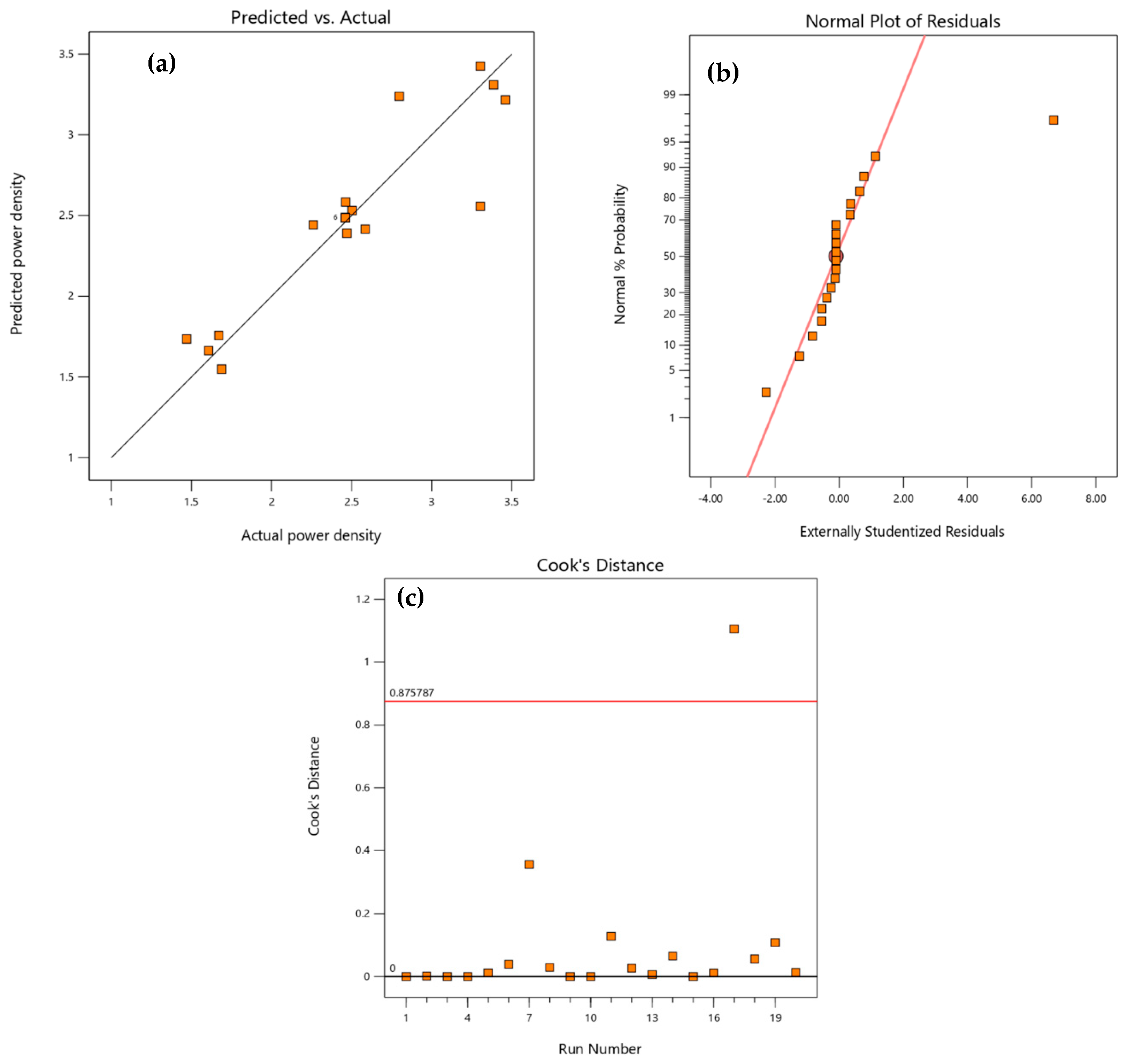
2.2. Model Validation

After preliminary validation using ANOVA, the model was further validated graphically by plotting different graphs (Figure 1). Figure 1a depicts the relation between the actual and the predicted values, which indicates that there exists a strong correlation between the two values and that the model is valid with a negligible amount of inaccuracy for practical purposes.
Model adequacy studentized residuals is basically the difference between the actual response value and the best fit value based on the developed model [24,25]. Figure 1b presents the model adequacy studentized residuals for the present study. From this figure, it can be concluded that the study does not include any sort of abnormality as the residual values for the model are insignificant. From the plot shown in Figure 1c, it can be observed that only one point lies outside the Cook’s distance, which means that a substantial number of points lies within the acceptable region. This further implies that there are no such potentially powerful points that may affect the response abnormally owing to their location in the plot [26,27]; hence, the model can be considered significant.

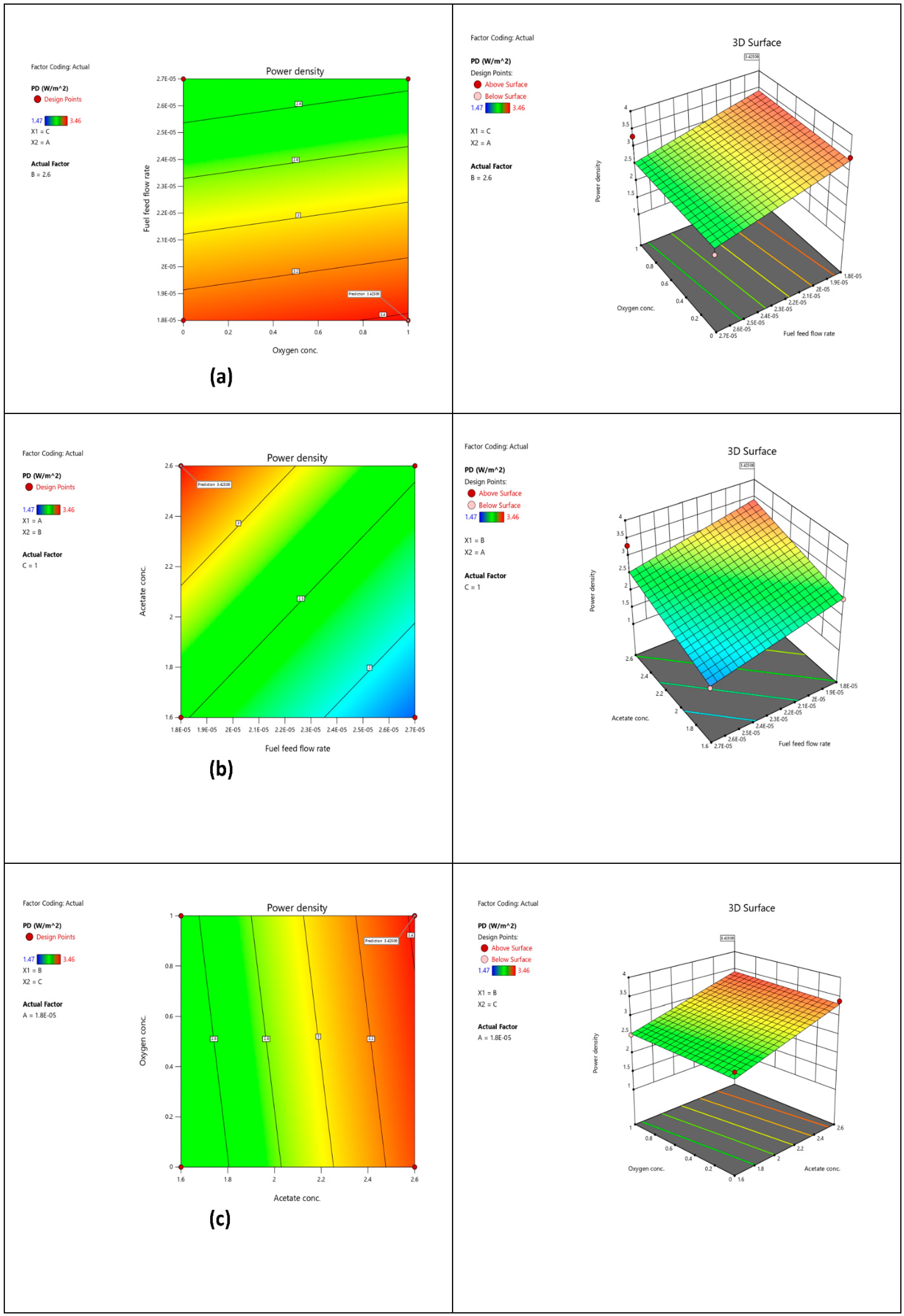
2.3. Optimal Conditions

After verifying the validity of the model, the next step was to interpret the results and find the optimal design points. The developed analytical model was used to generate contour plots and response surface plots against the control variables to study the effect of independent parameters on power density. An understanding of the interactions of variables is essential for achieving the highest power density. The three-dimensional response surface helps in the visualization of the interactions between the variables. However, for simplification, contour plots can also be used. Figure 2 depicts the contour plots and the 3D response surfaces for the interaction between power density, acetate concentration, oxygen concentration, and fuel feed flow rate.
Figure 2a shows the combined effect of the interaction between oxygen concentration and fuel feed flow rate on power density. It can be observed from Figure 2 that the power density increases with the increase in oxygen concentration, while keeping the fuel feed flow rate below 1.9 × 10⁻⁵ m3·h−1. Accordingly, the highest power density value of 3.42 W·m−2 occurred at a fuel feed flow rate of 1.8 × 10⁻⁵ m3·h−1 and an oxygen concentration of 1 mol·m-3. This point, with the highest power density, was considered as the optimal design point.
Figure 2b relates the effect of fuel feed flow rate and acetate concentration on power density. The trend suggests that an increment in the acetate concentration has a significant effect on the power density. It was realized that the power density attained its maximum value at an acetate concentration of 2.6 mol·m−3 and a fuel feed flow rate of 1.8 × 10⁻⁵ m3·h−1. Similarly, Figure 2c depicts the response of the power density upon variation of the acetate and the oxygen concentrations. The power density was found to be dependent on the concentration of both reactants. The highest value of power density was obtained at an acetate concentration of 2.6 mol·m−3 and an oxygen concentration of 1 mol·m−3.
Based on the optimization study, the different obtained results have been depicted in Table 1. Fuel feed flow rate, initial acetate concentration and initial oxygen concentration values of 0.00 m3·h−1, 2.60 mol·m−3, and 1.00 mol·m−3, respectively, have been determined to be the optimum values that resulted in the generation of the maximum power density (i.e., 3.425 W·m−2). The obtained results were somewhat predictable, based on the already available literature on MFCs.
Cathodic reactions have always been of interest to the research community, as it is usually observed that the performance of an MFC is limited by cathodic reactions [28]. In this study, upon changing the cathodic concentrations, by keeping other variables constant, a substantial increment in the MFC performance was observed. With respect to the fuel feed flowrate at the anode, a recent study was performed by You et al. [29]. After a series of experiments, it was noted that a higher fuel feed flow rate does not result in an enhancement of the power density of an MFC. Therefore, a low fuel feed flow rate was recommended. This finding lies in line with the present finding, as the optimization study revealed that the maximum power density is achievable at a hypothetically low fuel feed flow rate (ideally at 0 m3·h−1). It must be mentioned here that in case of very low substrate concentration (say, 2.0 mM), an increase in the flow rate resulted in an initial increase in the power density; however, following this initial increase, no further change in the power density was observed with increase in the flow rate. Therefore, it can be concluded that increasing the fuel feed flowrate results in a decrease in the power density (an observation that lies in line with the published literature) [21,30]. With respect to acetate concentration, a recent study showed that a medium level (for instance, between 500 and 3000 mg·L−1 of acetate concentration, the highest power output was achieved at a concentration of 2000 mg·L−1) of acetate concentration is favorable towards the achievement of the maximum power density [31], which agrees with the findings of this study.
From Table 1, it is pertinent to observe that the value of the flow rate of the fuel feed to the anodic chamber has been recommended to be 0.00 m3·h−1. This implies that a steady-state operation is recommended for obtaining the highest power density output. In other words, to attain the maximum power density, a particular amount of feed must be first introduced in the MFC, followed by an allowance of time to reach the steady-state. After reaching the steady-state, the power density output will be the maximum. However, after a certain point, the power density will start to decrease. At this very point, it is recommended to empty the fuel cell and introduce a new feed. This recommendation lies in line with that suggested by Esfandyari et al. [32].

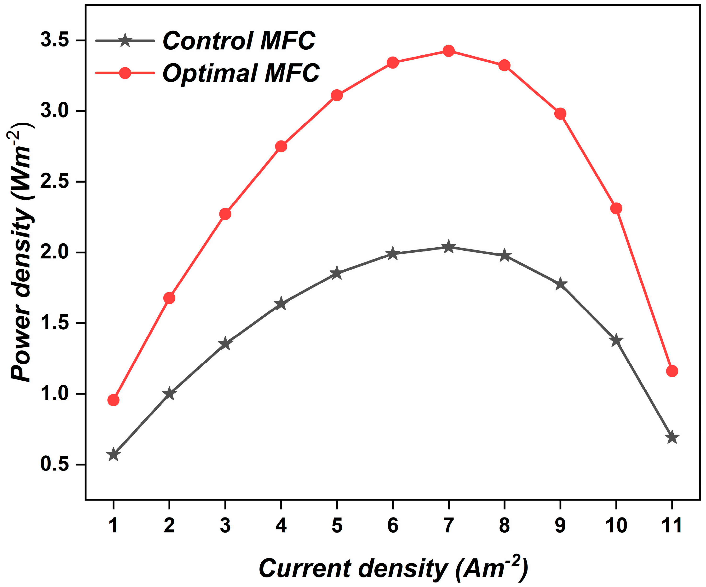
2.4. Validation of Optimization

The optimal conditions recommended by the numerical model have been highlighted in Table 1. The statistical model, Equation (1), predicts that under the mentioned optimal conditions, the power density must be 3.425 W·m−2. In order to validate these optimal results, a comparative study was conducted in which the power density of the control MFC was compared to that of the optimized MFC (see Figure 3). The control cell was operated at a fuel feed flow rate of 2.25 × 10⁻⁵ m3·h−1, an influent acetate concentration of 1.56 mol·m−3 and an influent oxygen concentration of 0 mol·m−3; whereas, the optimized MFC was operated at the proposed optimized conditions. All the experiments were performed at least twice and average values are stated. On average, a marginally insignificant value of deviation (2%) was observed. It was observed that the optimized MFC produced a much higher power density compared to the control MFC. Hence, the objective of the study was achieved. The obtained results, when compared to the literature, revealed that the maximum power density reported in an earlier study with the same experimental setup, but without optimization, was 2.039 W·m−2 [21]. Therefore, it is evident that, because of the optimization, an open circuit maximum power density of 3.425 W·m−2 could be achieved in the present study, with an average deviation of 2%.

3. Materials and Methods

3.1. MFC Design

To conduct this study, a dual chamber microbial fuel cell was constructed with the following specifications. A transparent sheet of polyacrylic plastic was used to construct both chambers of the MFC. The two chambers, i.e., the anodic and the cathodic chambers, were constructed with an equal volume of 5.5 cm3 and equal dimensions of 5.5 cm × 1.0 cm × 1.0 cm. An anode, having dimensions of 4.5 cm × 1.0 cm × 0.5 cm and made of graphite felt was used in this experiment. For this purpose, analytical grade polyacrylonitrile-based graphite felt was purchased from Beijing Sanys Carbon (Beijing, China) Co., Ltd. Both the anodic and the cathodic chambers were modeled as continuously stirred tank reactors. The cathode also possessed the same dimensions and materials, apart from the fact that it was coated with 0.3 mg·cm−2 of platinum powder. The catalyst was first magnetically stirred with isopropanol and 5 wt% Nafion solutions, followed by sonication for a period of 30 min to obtain a fine ink for the catalyst. The obtained ink was then carefully deposited onto the surface of the electrode by employing the spray coating technique [33]. To separate both the chambers, Nafion 117 membrane, having an area of 5 cm2, a thickness of 0.1778 mm and a conductivity of 5 S·m−1, was used. The anode and the cathode chambers were connected by using a platinum wire that was externally connected to a variable resistance box of 10–10 k Ω, that was systematically varied during the experiments and results were obtained by using Ohm’s law. The maximum power density value was obtained against an external resistance of 1 kΩ. Upon increasing the resistance value, rapid drop of voltage was observed. The design of this MFC was inspired by the design reported by Zeng et al. [21].

3.2. MFC Feed: Inoculation and Anolyte Preparation

For this study, we used an electrogenic-mixed firmicute consortium. The consortium was isolated from the anode electrode biofilm of an MFC operated with wastewater collected from the Karachi Water & Sewerage Board (KWSB), operated in fed-batch mode over a period of 6 months. Upon isolation consortium it was revealed that the isolated microbes belonged to the Lysinibacillus species, that contributes to make MFC cost effective [34]. For DNA isolation, PCR amplification and anolyte preparation, we closely followed the techniques described elaborately by Kumar et al. [35,36,37] and Rudra et al. [38]. These mixed strains were suspended in the buffer solution and subsequently transferred to synthetic feed wastewater to make the final volume of the microbial enriched anolyte. Inoculation of the microbe colonies was performed in sterilized solution that contained nutrient broth. Growth was allowed under laboratory conditions (temperature: 37 °C, time: 24 to 48 h), by maintaining anoxic conditions the whole process. The synthetic feed was prepared using 1.56 mM acetate buffer solution, and it was used to conduct all the experiments. The buffer was prepared using 4 mM sodium acetate in conjunction with acetic acid. The pH of the buffer was maintained at 7. To maintain anaerobic conditions in the anodic chamber, N2 was purged through the solution, while the cathodic chamber was directly in contact with atmospheric air [16]. The external resistance of the circuit during the inoculation procedure was 10 kΩ to ensure high biomass yield.

3.3. Working Conditions

All the experiments were conducted under a steady temperature of 25−30 °C and a pressure of 1 atm. All the readings were obtained from the MFC once the steady state condition was achieved, which took about 36 min from the start of the device operation.

3.4. Experimental Design

The sensitivity analysis of all the parameters of the MFC was conducted by following Zeng et al. [21]. This study was conducted by varying one parameter at a time, while keeping all other parameters constant. In this study [21], it was observed that the fuel feed flow rate, the rate of reaction in the anodic chamber, the rate of electron transfer between two chambers, the initial acetate concentration, the initial oxygen concentration, the membrane thickness, the membrane conductivity and the distance between the chambers were the most influential parameters that determines the power density of an MFC.
In this study, for performing the RSM studies, Design Expert software by Stat-Ease, Inc. Minneapolis, MN-55413, USA was used. The maximum and minimum values of the employed independent parameters, along with the mean have been presented in Table 2.
To study the effects of control variables on the power density of MFCs, a total of 20 experiments were performed. The number of experiments were decided based on the formula given in Equation (2).
N = 2 k + 2 k + 6
In Equation (2), N denotes the total number of experiments required, while k is the total number of independent variables selected for a given study [39]. Furthermore, the first term on the right-hand side denotes the number of factorial points, followed by the number of axial points (the second term) and the center points (the third term). In the present study, the value of k is 3. This implies a total of 20 experiments, with 8 factorial points, 6 axial points, and 6 central points.
Table 3 lists all these experiments, with their corresponding values of power densities.

4. Conclusions

A microbial fuel cell is a promising source of green electricity that also simultaneously reduces organic waste. Despite being an appealing technology, it is still largely laboratory-based and has so far failed to find applications in the industrial sector. This is primarily owing to its low power density output. This study uses RSM to achieve an enhanced power density of MFCs. For this purpose, a central composite design was adopted and a series of 20 experiments were conducted. Based on the experimental results, a statistical model was developed that depicted the relation of three independent variables to power density output. The model was validated using the ANOVA test and Crook distance test. Based on all the experiments and the validated model, it has been inferred that fuel feed flow rate, initial acetate concentration and initial oxygen concentration values of 0.00 m3·h−1, 2.60 mol·m−3, and 1.00 mol·m−3, respectively, are the optimum values that provide the maximum power density of 3.425 W·m−2. Additionally, this study successfully resulted in an improvement of the power density of an MFC from 2.039 W·m−2 (maximum value reported in the literature for a similar study) to 3.425 W·m−2.

Author Contributions

Conceptualization, M.N.N. and A.A.Z.; Data curation, H.K., S.K. and M.T.b.O.; Formal analysis, M.N.N., A.A.Z., H.K., Y.A.W. and K.D.; Funding acquisition, Y.A.W., N.A.H., I.A.B. and H.A.; Investigation, M.N.N.; Methodology, M.N.N., K.D. and J.J.; Project administration, A.A.Z., Y.A.W., K.D., J.J. and N.A.H.; Resources, H.K., Y.A.W., J.J., N.A.H. and H.H.; Software, S.K., M.T.b.O., M.A.I. and H.H.; Supervision, A.A.Z., Y.A.W., K.D. and J.J.; Validation, M.N.N., Y.A.W., M.A.I. and H.H.; Visualization, S.K., M.T.b.O., M.A.I. and H.H.; Writing—original draft, M.N.N. and H.K.; Writing—review & editing, A.A.Z., K.D., I.A.B. and H.A. All authors have read and agreed to the published version of the manuscript.

Funding

This work was supported by the University of Malaya through grant number ST030-2019. The authors also extend their appreciation to the Deanship of Scientific Research at King Khalid University for funding this work through a research group program under grant number RGP. 2/166/42.

Data Availability Statement

The authors confirm that the data supporting the findings of this study are available within the article.

Conflicts of Interest

The authors declare no conflict of interest.

References

  1. Jayapiriya, U.; Goel, S. Influence of cellulose separators in coin-sized 3D printed paper-based microbial fuel cells. Sustain. Energy Technol. Assess. 2021, 47, 101535. [Google Scholar]
  2. Naseer, M.N.; Zaidi, A.A.; Khan, H.; Kumar, S.; bin Owais, M.T.; Jaafar, J.; Suhaimin, N.S.; Wahab, Y.A.; Dutta, K.; Asif, M.; et al. Mapping the field of microbial fuel cell: A quantitative literature review (1970–2020). Energy Rep. 2021, 7, 4126–4138. [Google Scholar] [CrossRef]
  3. Din, M.I.; Nabi, A.G.; Hussain, Z.; Khalid, R.; Iqbal, M.; Arshad, M.; Muhjahid, A.; Hussain, T. Microbial fuel cells—A preferred technology to prevail energy crisis. Int. J. Energy Res. 2021, 45, 8370–8388. [Google Scholar] [CrossRef]
  4. Rossi, R.; Fedrigucci, A.; Setti, L. Characterization of electron mediated microbial fuel cell by Saccharomyces cerevisiae. Chem. Eng. Trans. 2015, 43, 337–342. [Google Scholar]
  5. Li, W.-W.; Sheng, G.-P.; Yu, H.-Q. Chapter 14-Electricity Generation from Food Industry Wastewater Using Microbial Fuel Cell Technology, in Food Industry Wastes; Kosseva, M.R., Webb, C., Eds.; Academic Press: San Diego, CA, USA, 2013; pp. 249–261. [Google Scholar]
  6. Cusick, R.D.; Kiely, P.D.; Logan, B.E. A monetary comparison of energy recovered from microbial fuel cells and microbial electrolysis cells fed winery or domestic wastewaters. Int. J. Hydrogen Energy 2010, 35, 8855–8861. [Google Scholar] [CrossRef]
  7. Kim, J.R.; Premier, G.C.; Hawkes, F.R.; Rodríguez, J.; Dinsdale, R.M.; Guwy, A.J. Modular tubular microbial fuel cells for energy recovery during sucrose wastewater treatment at low organic loading rate. Bioresour. Technol. 2010, 101, 1190–1198. [Google Scholar] [CrossRef]
  8. Trapero, J.; Horcajada, L.; Linares, J.J.; Lobato, J. Is microbial fuel cell technology ready? An economic answer towards industrial commercialization. Appl. Energy 2017, 185, 698–707. [Google Scholar] [CrossRef]
  9. Gajda, I.; Greenman, J.; Ieropoulos, I.A. Recent advancements in real-world microbial fuel cell applications. Curr. Opin. Electrochem. 2018, 11, 78–83. [Google Scholar] [CrossRef]
  10. Algar, C.K.; Howard, A.; Ward, C.; Wanger, G. Sediment microbial fuel cells as a barrier to sulfide accumulation and their potential for sediment remediation beneath aquaculture pens. Sci. Rep. 2020, 10, 13087. [Google Scholar] [CrossRef]
  11. Sarabia, L.A.; Ortiz, M.C. 1.12-Response Surface Methodology, in Comprehensive Chemometrics; Brown, S.D., Tauler, R., Walczak, B., Eds.; Elsevier: Oxford, UK, 2009; pp. 345–390. [Google Scholar]
  12. Khuri, A.I.; Mukhopadhyay, S. Response surface methodology. WIREs Comput. Stat. 2010, 2, 128–149. [Google Scholar] [CrossRef]
  13. Aydar, A.Y. Utilization of response surface methodology in optimization of extraction of plant materials. Stat. Approaches Emphas. Des. Exp. Appl. Chem. Process. 2018, 1, 157–169. [Google Scholar]
  14. Feng, R.; Zaidi, A.A.; Zhang, K.; Shi, Y. Optimisation of Microwave Pretreatment for Biogas Enhancement through Anaerobic Digestion of Microalgal Biomass. Period. Polytech. Chem. Eng. 2018, 63, 65–72. [Google Scholar] [CrossRef] [Green Version]
  15. Zaidi, A.A.; Khan, S.Z.; Shi, Y. Optimization of nickel nanoparticles concentration for biogas enhancement from green algae anaerobic digestion. Mater. Today: Proc. 2020, 39, 1025–1028. [Google Scholar] [CrossRef]
  16. Sarafraz, M.; Safaei, M.R.; Goodarzi, M.; Arjomandi, M. Experimental investigation and performance optimisation of a catalytic reforming micro-reactor using response surface methodology. Energy Convers. Manag. 2019, 199, 111983. [Google Scholar] [CrossRef]
  17. Geetanjali; Rani, R.; Sharma, D.; Kumar, S. Optimization of operating conditions of miniaturize single chambered microbial fuel cell using NiWO4/graphene oxide modified anode for performance improvement and microbial communities dynamics. Bioresour. Technol. 2019, 285, 121337. [Google Scholar] [CrossRef]
  18. Sedighi, M.; Aljlil, S.A.; Alsubei, M.D.; Ghasemi, M.; Mohammadi, M. Performance optimisation of microbial fuel cell for wastewater treatment and sustainable clean energy generation using response surface methodology. Alex. Eng. J. 2018, 57, 4243–4253. [Google Scholar] [CrossRef]
  19. Islam, M.A.; Ong, H.R.; Ethiraj, B.; Cheng, C.K.; Khan, M.R. Optimization of co-culture inoculated microbial fuel cell performance using response surface methodology. J. Environ. Manag. 2018, 225, 242–251. [Google Scholar] [CrossRef]
  20. Almatouq, A.; Babatunde, A. Identifying optimized conditions for concurrent electricity production and phosphorus recovery in a mediator-less dual chamber microbial fuel cell. Appl. Energy 2018, 230, 122–134. [Google Scholar] [CrossRef]
  21. Zeng, Y.; Choo, Y.F.; Kim, B.-H.; Wu, P. Modelling and simulation of two-chamber microbial fuel cell. J. Power Sources 2010, 195, 79–89. [Google Scholar] [CrossRef]
  22. Cheng, C.-L.; Shalabh; Garg, G. Coefficient of determination for multiple measurement error models. J. Multivar. Anal. 2014, 126, 137–152. [Google Scholar] [CrossRef] [Green Version]
  23. David, I.; Adubisi, O.; Ogbaji, O.; Eghwerido, J.; Umar, Z. Resistant measures in assessing the adequacy of regression models. Sci. Afr. 2020, 8, e00437. [Google Scholar] [CrossRef]
  24. Zhu, L. Checking the adequacy of a partially linear model. Nonparametric Monte Carlo Tests Appl. 2005, 1, 61–83. [Google Scholar]
  25. Chapter 5-Applications. In Inference for Heavy-Tailed Data Analysis; Academic Press: Cambridge, MA, USA, 2017; pp. 133–158.
  26. Chattoraj, S.; Mondal, N.K.; Das, B.; Roy, P.; Sadhukhan, B. Biosorption of carbaryl from aqueous solution onto Pistia stratiotes biomass. Appl. Water Sci. 2013, 4, 79–88. [Google Scholar] [CrossRef] [Green Version]
  27. Dalma, K.E.; Haydee, K.M.; Radu, T. Dynamic modelling of pesticides uptake by triticum spp. Anatomical compartments. Agric. Food 2016, 4, 215–228. [Google Scholar]
  28. Zhao, F.; Harnisch, F.; Schröder, U.; Scholz, F.; Bogdanoff, P.; Herrmann, I. Challenges and Constraints of Using Oxygen Cathodes in Microbial Fuel Cells. Environ. Sci. Technol. 2006, 40, 5193–5199. [Google Scholar] [CrossRef] [PubMed]
  29. You, J.; Greenman, J.; Ieropoulos, I. Novel Analytical Microbial Fuel Cell Design for Rapid in Situ Optimisation of Dilution Rate and Substrate Supply Rate, by Flow, Volume Control and Anode Placement. Energies 2018, 11, 2377. [Google Scholar] [CrossRef] [Green Version]
  30. Moon, H.; Chang, I.S.; Kim, B.H. Continuous electricity production from artificial wastewater using a mediator-less microbial fuel cell. Bioresour. Technol. 2006, 97, 621–627. [Google Scholar] [CrossRef]
  31. Ullah, Z.; Zeshan, S. Effect of substrate type and concentration on the performance of a double chamber microbial fuel cell. Water Sci. Technol. 2019, 81, 1336–1344. [Google Scholar] [CrossRef]
  32. Esfandyari, M.; Fanaei, M.A.; Gheshlaghi, R.; Mahdavi, M.A. Mathematical modeling of two-chamber batch microbial fuel cell with pure culture of Shewanella. Chem. Eng. Res. Des. 2017, 117, 34–42. [Google Scholar] [CrossRef]
  33. Nandy, A.; Kumar, V.; Mondal, S.; Dutta, K.; Salah, M.; Kundu, P.P. Performance evaluation of microbial fuel cells: Effect of varying electrode configuration and presence of a membrane electrode assembly. New Biotechnol. 2015, 32, 272–281. [Google Scholar] [CrossRef] [PubMed]
  34. Nandy, A.; Kumar, V.; Kundu, P.P. Utilization of proteinaceous materials for power generation in a mediatorless microbial fuel cell by a new electrogenic bacteria Lysinibacillus sphaericus VA5. Enzym. Microb. Technol. 2013, 53, 339–344. [Google Scholar] [CrossRef] [PubMed]
  35. Kumar, V.; Nandy, A.; Das, S.; Salahuddin, M.; Kundu, P.P. Performance assessment of partially sulfonated PVdF-co-HFP as polymer electrolyte membranes in single chambered microbial fuel cells. Appl. Energy 2015, 137, 310–321. [Google Scholar] [CrossRef]
  36. Kumar, V.; Kumar, P.; Nandy, A.; Kundu, P.P. Crosslinked inter penetrating network of sulfonated styrene and sulfonated PVdF-co-HFP as electrolytic membrane in a single chamber microbial fuel cell. RSC Adv. 2015, 5, 30758–30767. [Google Scholar] [CrossRef]
  37. Kumar, V.; Kumar, P.; Nandy, A.; Kundu, P.P. A nanocomposite membrane composed of incorporated nano-alumina within sulfonated PVDF-co-HFP/Nafion blend as separating barrier in a single chambered microbial fuel cell. RSC Adv. 2016, 6, 23571–23580. [Google Scholar] [CrossRef]
  38. Rudra, R.; Kumar, V.; Kundu, P. Acid catalysed cross-linking of poly vinyl alcohol (PVA) by glutaraldehyde: Effect of crosslink density on the characteristics of PVA membranes used in single chambered microbial fuel cells. RSC Adv. 2015, 5, 83436–83447. [Google Scholar] [CrossRef]
  39. Hosseinpour, M.; Vossoughi, M.; Alemzadeh, I. An efficient approach to cathode operational parameters optimization for microbial fuel cell using response surface methodology. J. Environ. Health Sci. Eng. 2014, 12, 33. [Google Scholar] [CrossRef] [Green Version]
Figure 1. Analytical model validation graphs. (a) Predicted vs. actual. (b) Normal plot of residuals. (c) Cook’s distance.
Catalysts 11 01202 g001
Figure 2. Contour plots of optimization to study the effect of the selected independent parameters on the MFC power density: (a) Effect of oxygen concentration and fuel feed flowrate, (b) effect of fuel feed flowrate and acetate concentration, and (c) effect of acetate concentration and oxygen concentration.
Catalysts 11 01202 g002
Figure 3. Comparative analysis of the control and the optimized MFCs.
Catalysts 11 01202 g003
Table 1. Consolidated results of the optimization study.
No.Flow Rate of Fuel Feed to Anode
(m3·h−1)
Concentration of Acetate in Anode
(mol·m−3)
Concentration of Oxygen in Cathode
(mol·m−3)
Power Density
(W·m−2)
Desirability
10.002.601.003.425060.99411298Selected
20.002.600.923.416410.99264417-
30.002.600.903.413670.99217825-
40.002.600.893.412460.99196836-
50.002.600.883.411260.9917674-
60.002.600.853.407720.9911634-
70.002.600.833.40510.990717-
80.002.600.793.400820.98998557-
90.002.601.003.417260.9898039-
100.002.600.763.397490.98941787-
Table 2. Values of independent variables used for the process optimization.
SymbolParameterUnitMinimumMaximumMean
AFlow rate of fuel feed to anodem3 h−102.25 × 10−51.12 × 10−5
BInitial concentration of acetate in anodemol m−31.262.942.1
CInitial concentration of oxygen in cathodemol m−30.341.340.5
Table 3. Central composite design of experiments for optimization of the MFC.
Factor 1Factor 2Factor 3Response
RunTypeABCR
m3 h−1mol m−3mol m−3W m−2
1Axial2.25 × 10−52.9408960.52.797
2Center2.25 × 10−52.10.52.461
3Axial3.01 × 10−52.10.51.671
4Axial2.25 × 10−51.2591040.51.47
5Axial2.25 × 10−52.11.3408962.463
6Factorial0.0000271.611.607
7Factorial0.0000272.613.304
8Center2.25 × 10−52.10.52.461
9Center2.25 × 10−52.10.52.461
10Axial1.49 × 10−52.10.53.46
11Factorial0.0000272.602.261
12Factorial0.0000182.603.386
13Factorial0.0000181.612.503
14Factorial0.0000181.602.585
15Factorial0.0000182.613.304
16Center2.25 × 10−52.10.52.461
17Factorial0.0000271.601.689
18Center2.25 × 10−52.10.52.461
19Axial2.25 × 10−52.10.34092.47
20Center2.25 × 10−52.10.52.461
Publisher’s Note: MDPI stays neutral with regard to jurisdictional claims in published maps and institutional affiliations.

