Article

Ni-N-Doped Carbon-Modified Reduced Graphene Oxide Catalysts for Electrochemical CO2 Reduction Reaction

1
School of Chemistry and Chemical Engineering, Shandong University of Technology, Zibo 255000, China
2
Key Laboratory of Optic-Electric Sensing and Analytical Chemistry for Life Science, MOE, Shandong Key Laboratory of Biochemical Analysis, College of Chemistry and Molecular Engineering, Qingdao University of Science and Technology, Qingdao 266042, China
*
Authors to whom correspondence should be addressed.
Catalysts 2021, 11(5), 561; https://doi.org/10.3390/catal11050561
Submission received: 14 March 2021 / Revised: 19 April 2021 / Accepted: 25 April 2021 / Published: 28 April 2021

Abstract

:
Electrochemical CO2 reduction reaction (CO2RR) is eliciting considerable attention in relation to the carbon cycle and carbon neutrality. As for the practical application of CO2RR, the electrocatalyst is a crucial factor, but, even so, designing and synthesizing an excellent catalyst remains a significant challenge. In this paper, the coordination compound of Ni ions and dimethylglyoxime (DMG) was employed as a precursor to modify reduced graphene oxide (rGO) for CO2RR. The textural properties and chemical bonds of as-obtained rGO, N–C–rGO, Ni–rGO, Ni–N–C, and Ni–N–C–rGO materials were investigated in detail, and the role of Ni, N–C, and rGO in the CO2RR were researched and confirmed. Among all the catalysts, the Ni–N–C–rGO showed the optimal catalytic activity and selectivity with a high current density of 10 mA cm−2 and FE(CO)% of 85% at −0.87 V vs. RHE. In addition, there was no obvious decrease in activity for 10 h. Therefore, the Ni–N–C–rGO is a promising catalyst for CO2RR to CO.

Graphical Abstract

1. Introduction

From the massive utilization of fossil fuels, the concentration of CO2 in the atmosphere has gradually increased, which has caused a series of alarming environmental problems [1,2]. Therefore, there is an urgent need to reduce the amount of CO2 and realize the carbon cycle and carbon neutrality. In recent years, different kinds of strategies have been explored to convert CO2 into high value-added products [3,4,5]. Among these strategies, the electrocatalytic CO2 reduction reaction (CO2RR) to produce valuable products has attracted continuous attention, and can use renewable energies (e.g., wind energy, solar energy, and tidal energy) as a driving force [6,7,8].
The CO2RR, is a typical multi-proton and multi-electron process in which a variety of intermediates (e.g., *COOH, *CO, *CH2, and *CHO) might be produced [9,10]. The different ability of adsorption and activation intermediates on active sites of the catalyst will guide the reaction through different pathways and obtain different products (e.g., CO, HCOOH, CH4, and C2H4) [11,12,13,14]. In addition, the aqueous solution is usually employed as an electrolyte. In this condition, the hydrogen evolution reaction (HER), which can happen under low over-potential, is a strong competing reaction for CO2RR [15,16]. Consequently, the key for CO2RR is to design and fabricate electrocatalysts with high selectivity and current density.
Owing to the unique two-dimensional carbon structure, graphene-based materials with an excellent capacity for electron transfer, play an important role in the field of electrocatalysts [17,18]. Furthermore, due to the large surface area and good conductivity of graphene-based materials, they have also been widely used as effective supports for metal nanoparticles, thereby providing a synergistic effect to enhance catalytic activity [19,20]. As for CO2RR, the reduced graphene oxide (rGO) lacks catalytic active sites for adsorption and activation of CO2 molecules. Hence, it is necessary to introduce accessional active sites for CO2RR to modify rGO material.
Currently, different noble metals (e.g., Au, Ag, and Pd) are taken to modify rGO material and are employed as catalysts for CO2RR to CO [21,22,23]. However, the high cost and shortage of noble metals have severely hindered their widespread application in CO2RR. Therefore, cheap and earth-rich transition metals are possible alternative options and have drawn much attention [24,25,26]. The Ni-N-doped carbon (Ni–N–C) has been proved to be a promising catalyst for CO2RR to CO [27,28,29]. However, the efficient combination of Ni–N–C and rGO is still a significant challenge. In addition, the promotion mechanism of different roles (e.g., Ni, N–C, and rGO) should be further illustrated to guide the fabrication of a high efficiency catalyst.
As a typical qualitative and quantitative method for detecting Ni ions, dimethylglyoxime (DMG) is well known, as it can form complexes with Ni ions [30,31]. Inspired by this characteristic reaction, we used Ni–DMG complex as precursor to combine with GO, and then prepared Ni–N–C modified rGO (Ni–N–C–rGO) catalyst for CO2RR. The mechanism of action of each component (e.g., Ni, N–C, and rGO) in the catalyst was analyzed to provide a reference for the design and fabrication of electrocatalyst for CO2RR. The Ni–N–C–rGO catalyst showed high activity and stability (a current density of 10 mA cm−2 and FE(CO)% of 85% at −0.87 V vs. RHE for 10 h), and is a promising catalyst for CO2RR to CO.

2. Results

2.1. Textural Properties of Ni–N–C–rGO Materials

Figure 1 shows the schematic representation for the preparation of the Ni–N–C–rGO catalyst, which includes the synthesis of the Ni–DMG–GO and its subsequent thermal pyrolysis. Furthermore, for investigating the role of Ni, N–C, and rGO; the N–C–rGO, Ni–rGO, and Ni–N–C materials were fabricated by the same procedure without introducing Ni, DMG, and rGO, respectively.
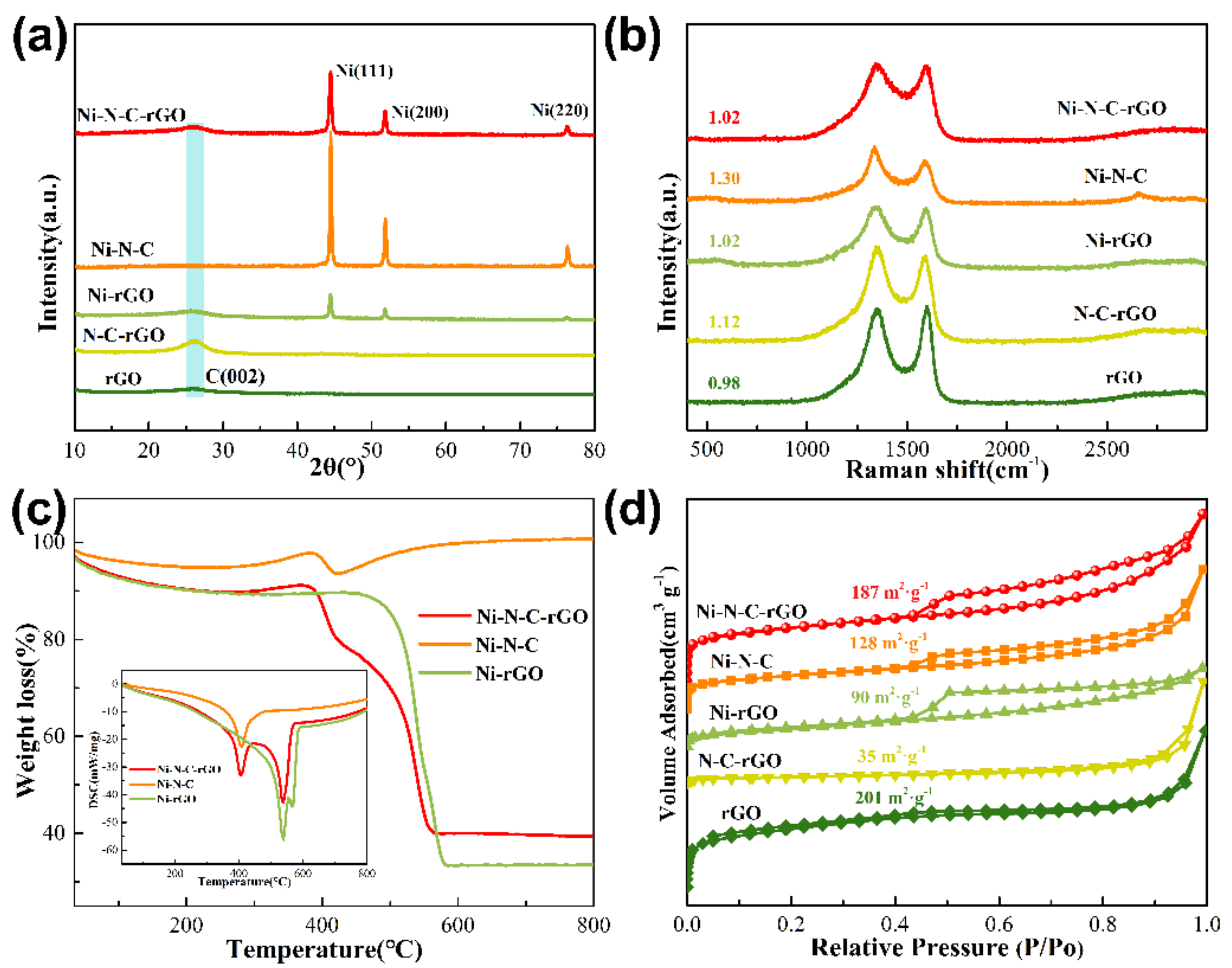
In the X-ray diffraction (XRD) patterns (Figure 2a), only a broad peak, which is attributed to the graphitic carbon structure, is detected in the rGO and N–C–rGO materials [32,33]. With the introduction of Ni species, three sharp diffraction peaks appear at 44.5°, 51.9°, and 76.4°, corresponding well with the (111), (200), and (220) crystal planes of metallic Ni (JCPDF card No. 04-0850), respectively, indicating that Ni ions are successfully reduced to metallic Ni particles in Ni–rGO, Ni–N–C, and Ni–N–C–rGO materials [34,35]. In addition, Ni–N–C material exhibits the strongest intensity, implying the highest Ni content. The crystalline size calculated from the Scherrer formula is 29.6, 37.0, and 24.7 nm for Ni–rGO, Ni–N–C, and Ni–N–C–rGO materials, respectively [36,37]. The large crystalline size of Ni–N–C is ascribed to the absence of rGO, which can improve the dispersion of Ni species.
Raman spectroscopy was conducted to reveal the structure of the obtained materials and verify the modification of graphene. As displayed in Figure 2b, two vibrational bands positioned at 1340 cm−1 (disordered carbon (D band)) and 1590 cm−1 (graphitic carbon (G band)) are clearly detected. Generally, the ratio of D band and G band intensity (ID/IG) is an indicator of the quantity of disordered and graphitic carbon in the framework [38,39]. Compared with the rGO, the ID/IG value of N–C–rGO, Ni–rGO, and Ni–N–C–rGO materials increase, and this may be due to the modification of graphene. For the N–C–rGO, the value increases to 1.12, showing the aggregation of rGO with the modification of N–C structure. This result is further confirmed by the following N2 absorption–desorption isotherms. For the Ni–N–C material, the high ID/IG value indicates the existence of large amounts of disordered carbon structure. Compared with the graphitic carbon structure, this disordered one is not beneficial for the transmission of electrons in the reaction process.
To accurately analyze the contents of Ni species, the thermogravimetric differential scanning calorimetry (TG-DSC) profiles of Ni–N–C–rGO composites under air atmosphere were obtained. The obvious weight loss with exothermic peaks occurs at 400–600 °C (Figure 2c), which is assigned to the decomposition of C and N species, and the residual weight above 600 °C is ascribed to the NiO species in the materials. The contents of Ni species obtained from TG characterization are 26.4, 79.3, and 30.8 wt% for Ni–rGO, Ni–N–C, and Ni–N–C–rGO samples, respectively. As for the DSC profiles (inset of Figure 2c), the Ni–N–C exhibits the smallest exothermic peak, implying the least C and N content in these three samples. Furthermore, the initial reaction temperature (400 °C) of Ni–N–C and Ni–N–C–rGO is lower than that of Ni–rGO (550 °C). This is due to the presence of N species in the material, which are beneficial for the oxidation reaction, further illustrating the presence of N species in the material.
N2 adsorption-desorption isotherms (Figure 2d) were obtained to investigate the textural properties of obtained materials. Conversely, no obvious hysteresis loop is observed in the rGO and N–C–rGO, indicating that no mesoporous structure exists. For the Ni–rGO, Ni–N–C, and Ni–N–C–rGO samples, a type-IV isotherm with H2 hysteresis loop is observed, implying the existence of abundant mesoporous structure [40,41], which may be caused by the catalytic graphitization of Ni species in the thermal pyrolysis. Moreover, the N–C–rGO material exhibits a low specific surface area (35 m2 g−1), implying the aggregation of rGO sheets; further confirming the Raman spectra of N–C–rGO. The Ni–N–C–rGO has a larger specific surface area than Ni–N–C, implying that the excellent dispersity of graphene enhances the specific surface area of the material. The large surface area is favorable for promoting mass transport capacity and increasing exposed active sites.
Scanning electron microscope (SEM) images (Figure 3) were utilized to observe the surface morphology of the composite materials. The SEM images (Figure 3a) show a typical nanosheet-like morphology of rGO. As for the N–C–rGO (Figure 3b), the aggregation of rGO is observed, agreeing well with the result achieved from N2-physisorption. With the introduction of Ni species, the obvious Ni particles can be found in the Ni–rGO (Figure 3c), Ni–N–C (Figure 3d), and Ni–N–C–rGO (Figure 3e,f) materials. As for the Ni–N–C, a fibrous tubular structure is observed, in which the Ni particles are wrapped by a N–C skeleton. For the Ni–N–C–rGO, the fibrous tubular structure of Ni–N–C is uniformly dispersed on the rGO, confirming the formation of composite structure. The element mapping images (Figure 3g,h) of Ni–N–C and Ni–N–C–rGO reveal the distribution of C, N, O, and Ni elements, thus confirming the successful modification of Ni–N–C on the rGO support.
In the transmission electron microscope (TEM) images of Ni–rGO (Figure 4a), Ni–N–C (Figure 4b), and Ni–N–C–rGO (Figure 4c); Ni particles are observed, and the morphology observed in the TEM images agrees well with the results from the SEM images, indicating the formation of composite structure in Ni–N–C–rGO. For the HRTEM images (Figure 4d–f), it can be seen that the Ni particles are wrapped by the carbon skeleton. Specifically, in the core portion, the distinct lattice fringes with spacing of 0.209 nm, correspond to the (111) plane of metallic Ni. As for the shell portion, the Ni–N–C (Figure 4e) exhibits a disordered carbon structure. In contrast, graphitic carbon structure surrounds the Ni particle in the Ni–N–C–rGO material. This phenomenon further confirms the Raman spectra, in which the Ni–N–C–rGO shows a lower ID/IG value than Ni–N–C. More importantly, the graphitic carbon structure benefits the transfer of electrons and enhances the electrical conductivity of the catalyst. The element mapping images (Figure 4g) of Ni–N–C–rGO confirm the successful modification of Ni–N–C on the rGO support.

2.2. Chemical Bonds of Ni–N–C–rGO Materials

The chemical compositions and bonding configurations of the obtained materials were characterized by XPS. As shown in the full spectrum (Figure S1), the signals of C, N, O, and Ni are achieved. For the C1s spectra (Figure 5a), the spectra of these composite materials with similar configurations, are deconvoluted into three components. The main peak at 284.8 eV is assigned to sp2-hybridized graphite-like carbon (C–C), and the peaks at 285.9 eV are owing to a C–O group, or the sp2 carbon bond overlapped with nitrogen species [42]. The peak at 287.3 eV is ascribed to a C=O group [43]. For the O1s spectra (Figure 5b), three different peaks were determined at 529.8, 532.0, and 533.6 eV, corresponding to Ni–O, C=O, and C–O, respectively [44,45]. The Ni–O bond might be owing to the surface metallic Ni particles, which are partially oxidized in the air atmosphere. For the N1s spectra (Figure 5c), three types of nitrogen (pyridinic-N, pyrrolic-N, and graphitic-N) are observed at 398.7, 400.8, and 402.0 eV, respectively [46,47]. For the peak position of pyridine N, compared with N–C–rGO, the position of the peak shifts to the high binding energy with the introduction of Ni species (Ni–N–C and Ni–N–C–rGO), implying the formation of a coordinate bond between Ni and N, in which the lone pair electrons of N species transfer to the empty orbital of Ni species.
As shown in Figure 5d, the Ni signal at 852.7 eV corresponds to metallic Ni species [48]. The signal at 854.5 eV is due to the strong electron transmission between the Ni and N–C skeleton [49]. This result can also be confirmed by the Ni–rGO material, in which only Ni–Ni and Ni–O bonds exist in the Ni2p spectra. The signal at 856.5 eV is attributed to the Ni oxide, which may be caused by the oxidation of surface metallic Ni species [50]. The constituents determined from XPS spectra are given in Table 1. The changing law of Ni content agrees well with the results obtained from TG-DSC and EDS techniques (Table 1). However, the Ni contents determined from XPS are much lower than the results of TG and EDS measurements, indicating that most of the Ni particles are encased, so cannot be completely detected by the X-ray of XPS characterization. This phenomenon agrees well with the HRTEM results, in which the encased structure is clearly observed.

2.3. Catalytic Performance of Ni–N–C–rGO Materials

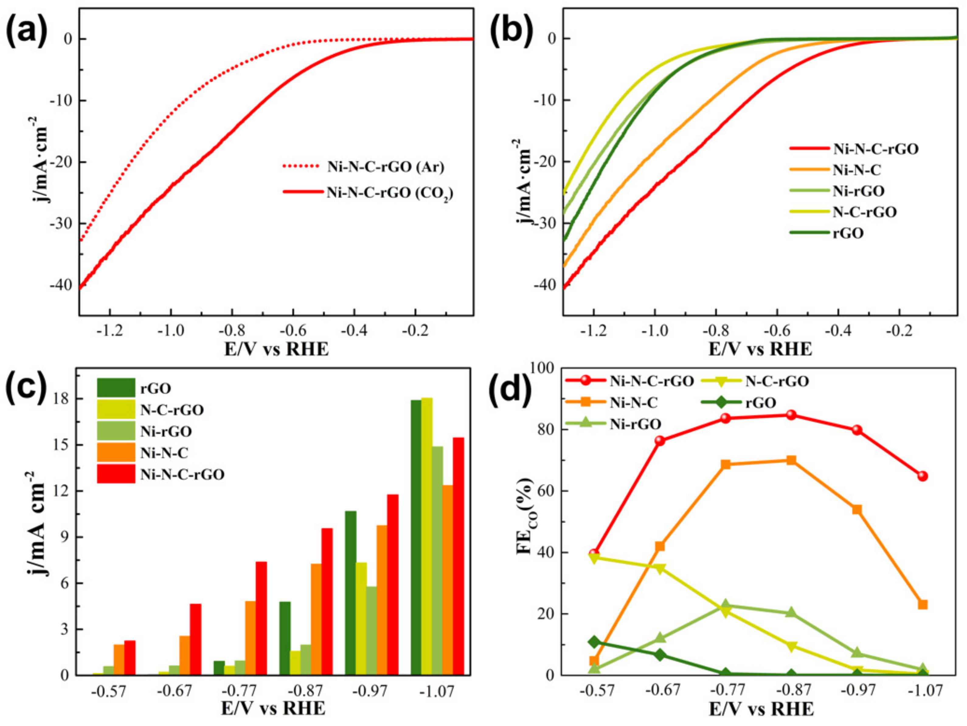
Inspired by the excellent structure of Ni–N–C–rGO materials, these catalysts were used for CO2RR. The linear sweep voltammetry (LSV) curves (Figure S2 and Figure 6a) of catalysts, under Ar or CO2 saturated 0.5 M KHCO3 electrolyte, were obtained and analyzed. Different from rGO, N–C–rGO, and Ni–rGO catalysts, the reduction current is markedly improved by the introduction of CO2 atmosphere in Ni–N–C and Ni–N–C–rGO catalysts. Especially for the Ni–N–C–rGO catalyst (Figure 6a), the reduction current drastically increases from −0.4 V as the electrolyte is saturated by CO2, and the onset potential is lower than that in an Ar atmosphere (−0.6 V); implying the excellent electrocatalytic activity toward CO2RR. Meanwhile, the Ni–N–C–rGO catalyst exhibits the lowest onset potential and highest current density among all the catalysts in a CO2 atmosphere (Figure 6b), suggesting its optimal catalytic activity for CO2RR.
The electrocatalytic performance of the Ni–N–C–rGO materials was further investigated by characterizing the current density and obtained products under different potentials. As shown in Figure 6c, the rGO, N–C–rGO, and Ni–rGO show a low current density under −0.87 V, and increase sharply from −0.87 to −1.07 V. As for the Ni–N–C and Ni–N–C–rGO catalysts, the current density increases linearly as the applied potential varies from −0.57 V to −1.07 V. In addition, the Ni–N–C–rGO catalyst owns a larger current density than Ni–N–C, and this is ascribed to the rGO, which is beneficial for the transmission of electrons to reactants.
As for the products, only CO and H2 were tested (Figure 6d and Figure S3). Regarding the rGO catalyst, little CO production is detected and the FE(CO)% is below 10%, implying the absence of active site for CO2RR in the rGO catalyst. With the modification of N–C or Ni, the FE(CO)% increases to 40% for N–C–rGO (−0.57 V), or 20% for Ni–rGO (−0.77 V). It can be seen that the FE(CO)% of these two catalysts is still unsatisfactory, especially under high current density. Either Ni or N–C cannot provide efficient active sites for CO2RR. Therefore, superior active sites for CO2RR to CO should be identified and employed to modify the rGO material. The catalytic performance of Ni–N–C material was investigated, and the FE(CO)% exhibits a volcano-type curve, and the highest value (70%) is obtained under −0.87 V. More importantly, the Ni–N–C–rGO catalyst shows a higher catalytic activity than Ni–N–C, and the FE(CO)% increases from 40% to 85% with the change in potential from −0.57 V to −0.87 V. In conclusion, the synergistic effect of Ni and N–C can provide active sites for CO2RR, and the rGO support can improve the dispersity of Ni–N–C active sites, enhancing the current density and FE(CO)% of catalysts in CO2RR.
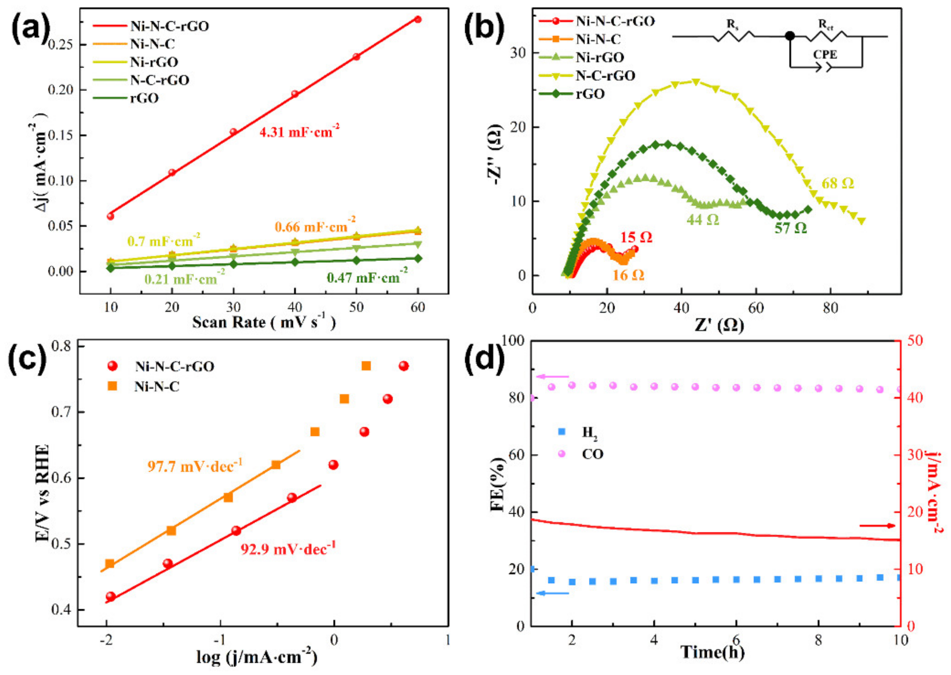
The electrochemical surface area (ECSA) was further determined to study the electrochemical activities of different catalysts (Figure 7a and Figure S4) [11,51]. The Cdl of Ni–N–C–rGO is higher than that of rGO, N–C–rGO, Ni–rGO, and Ni–N–C catalysts, indicating a larger ECSA and the existence of more active sites in the Ni–N–C–rGO catalyst. Therefore, it is favorable for enhancing the electrocatalytic activity of Ni–N–C–rGO, and indicates the increased apparent concentration of reactant on the catalyst, leading to a high efficiency for CO2RR. Meanwhile, electrochemical impedance spectroscopy (EIS) was conducted to investigate the properties of the electrode/electrolyte interface and reveal the interfacial charge-transfer resistance (Rct) of the catalysts. As shown in Figure 7b, Ni–N–C and Ni–N–C–rGO show the lower Rct than rGO, N–C–rGO, and Ni–rGO, implying their excellent ability for the transmission of electrons.
Tafel slopes were calculated to investigate the reaction kinetics on Ni–N–C and Ni–N–C–rGO catalysts towards CO2RR. The Tafel slopes of Ni–N–C and Ni–N–C–rGO approach 118 mV dec−1 (Figure 7c), implying that the rate-determining step of CO2RR is the transmission of the first electron to the CO2 molecule [52,53]. In addition, the Tafel slope of Ni–N–C for CO production of Ni–N–C is 97.7 mV dec−1, which is larger than that of Ni–N–C–rGO (92.9 mV dec−1), indicating sluggish kinetics for the activation process on Ni–N–C. The change law of Tafel slope is consistent with the LSV curves and current density curves under different potentials.
Meanwhile, the stability of the Ni–N–C–rGO catalyst was investigated by testing continuously under −0.87 V, which has the largest FE(CO)% (Figure 7d and Figure S5). No obvious decay in FE(CO)% is detected for 10 h of electrolysis, and only the current density attenuates slightly, demonstrating the long-term stability of the Ni–N–C–rGO catalyst. Therefore, the Ni–N–C–rGO is a promising catalyst for CO2RR to CO.

3. Materials and Methods

3.1. Materials

Nickel nitrate hexahydrate (Ni(NO3)2·6H2O, ≥98.0%), dimethylglyoxime (C4H8N2O2, ≥98.0%), N,N-dimethylformamide (C3H7NO, ≥99.5%), potassium bicarbonate (KHCO3, ≥99.5%), and ethanol (EtOH, ≥99.7%) were purchased from Aladdin Biochemical Technology Co., Ltd (Shanghai, China). Nafion solution (5 wt%) was purchased from Dupont company (Wilmington, DE, USA). All the reagents were used as received without further purification. Deionized water (18.2 MΩ) was used in our experiments.

3.2. Synthesis of Materials

3.2.1. Synthesis of Graphene Oxide (GO)

According to the modified Hummers’ method, the GO was prepared through the oxidation and purification of natural graphite powder [54,55].

3.2.2. Preparation of Different Precursors Ni–DMG–GO

The Ni(NO3)2 solution (0.1454 g Ni(NO3)2·6H2O in 3 mL of water) was mixed with 10 mL of 4 mg mL−1 GO suspension under stirring. After that, an appropriate amount of the DMG solution (Ni(NO3)2·6H2O:DMG = 1:2 (molar ratio)) was added to the above solution, and the aqueous solution was stirred at room temperature for 6 h. Thereafter, the resulting precipitates were centrifuged and washed with ethanol three times. The composites were finally obtained by freeze drying with a vacuum at −50 °C for 24 h. The obtained composites were denoted as Ni–DMG–GO.

3.2.3. Preparation of Ni–N–C–rGO Materials

The Ni–DMG–GO composites were suffered thermal annealing process in a N2 atmosphere at 800 °C for 3 h with a heating rate of 2 °C min−1. In this process, the Ni–DMG and GO were reduced to Ni–N–C and rGO, respectively. The resulting materials were denoted as Ni–N–C–rGO. For investigating the role of Ni, N–C, and rGO, the samples –without introducing Ni, DMG, and rGO–were fabricated by the same procedure and denoted as N–C–rGO, Ni–rGO, and Ni–N–C, respectively.

3.3. Materials Characterization

XRD patterns were performed on a D8 ADVANCE X-ray diffractometer (Bruker, Karlsruhe, Germany) with a Cu Kα radiation (λ = 1.5406 Å) source in the 2θ range from 10–80° at a scanning rate of 5° min−1. Raman spectra were measured using a CCD detector with a 532 nm laser beam on the LabRam HR system (HORIBA, Tokyo, Japan). The TG-DSC analysis was performed by a NETZSCH STA 449 F3 simultaneous TG-DSC instrument (NETZSCH-Gerätebau GmbH, Selb, Germany) at 10 °C min−1 in the air. N2 adsorption-desorption isotherms were conducted at 77 K using the Micromeritics 3Flex Physisorption (Micromeritics, Norcross, GA, USA) with degassed samples (300 °C for 2 h). The morphologies, microstructures, and constitution of the samples were characterized by SEM (FEI Quanta FEG 250, FEI company, Hillsboro, OR, USA) and TEM (FEI Tecnai G2 F20, FEI company, Hillsboro, OR, USA). X-ray photoelectron spectroscopy (XPS) was performed on a Thermo Scientific K-Alpha+ spectrometer (Thermo Fisher Scientific, Waltham, MA, USA).

3.4. Preparation of Working Electrodes

The preparation procedure for the working electrode was described as follows: 10 mg of as-prepared catalyst was uniformly dispersed into 5000 µL of mixture solution (5 wt% Nafion solution: N,N-dimethylformamide = 1:49) under sonication for 2 h. Then, the above obtained ink (100 µL) was dispersed on both sides of carbon paper (1.0 × 0.5 cm2) with the loading catalyst of 0.2 mg cm−2.

3.5. Electrochemical Measurements

Electrochemical measurements were conducted within H-type electrolytic cells using a CHI760E (CH Instruments, Inc., Shanghai, China) electrochemical workstation, and a three-electrode test was carried out in an H-cell which was separated by a Nafion-115 membrane (Dupont, Delaware, USA). A Pt plate served as a counter electrode, and Ag/AgCl (saturated KCl) acted as the reference electrode. The experiment was performed in CO2-saturated 0.5 M KHCO3, and CO2 gas was injected for 30 min before tests. All the potentials in this work were calibrated to RHE by the E (vs. RHE) = E (vs. Ag/AgCl) + 0.1989 V + 0.0592 × pH. At room temperature and atmospheric pressure, the gas products were delivered directly to the sampling loop of an on-line gas chromatograph (GC) equipped with a thermal conductivity detector (TCD), a flame ionization detector (FID) and a methanator assisted FID to analyze the gaseous products. The liquid products were analyzed by 1H nuclear magnetic resonance (1H NMR) spectrometer (Bruker AVANCE III 400, Bruker, Karlsruhe, Germany) with dimethylsulfoxide (DMSO) employed as an internal standard substance.
The Faradaic efficiency (FE) of the products was calculated using the following equation:
F E i = Z i × V i × G × F × P 0 I × R × T 0
Zi: the number of electrons for an i molecule, and Zi = 2 and 2 for CO and H2;
Vi: the volume ratio of product i;
G: the volumetric flow rate (10 mL min−1);
F: Faradaic constant (96,485 C mol−1);
P0: atmospheric pressure (1.013 × 10⁵ Pa);
I: the current at each applied potential;
R: ideal gas constant (8.314 J mol−1 K−1);
T0: reaction temperature (298 K).
The LSV curves were performed in CO2-saturated or Ar-saturated 0.5 M KHCO3 solutions with a scan rate of 5 mV s−1 between 0 to −1.3 V vs. RHE. The ECSA of the catalysts was calculated from their electrochemical double-layer capacitance (Cdl), which was determined by measuring the capacitive current associated with double-layer charging from the scan-rate dependence of the CV. The potential of the CV ranged from 0.20 to 0.30 V with various scan rates (10, 20, 30, 40, and 60 mV s−1) under a CO2 atmosphere. The Cdl was calculated by plotting the Δj = ja − jc at 0.25 V vs. the scan rate (ja and jc are the anodic and cathodic current densities), respectively. The slope was twice that of the Cdl value. The EIS measurement was performed using an electrochemical workstation (PARSTAT 4000) with an amplitude of 5 mV of 0.01 Hz to 10 KHz at −0.87 V.

4. Conclusions

In this paper, a series of rGO, N–C–rGO, Ni–rGO, Ni–N–C, and Ni–N–C–rGO materials were designed and fabricated. The investigation of textural properties, chemical bonds and catalytic performance of as-obtained modified rGO catalysts, indicated that the synergistic effect of Ni and N–C can provide active sites for CO2RR, and the rGO support can improve the dispersity of Ni–N–C active sites. The Ni–N–C–rGO showed the optimal catalytic activity and selectivity with a high current density of 10 mA cm−2 and FE(CO)% of 85% at −0.87 V vs. RHE. In addition, there was no obvious decrease in activity for 10 h. Therefore, the Ni–N–C–rGO is a promising catalyst for CO2RR to CO.

Supplementary Materials

The following are available online at https://www.mdpi.com/article/10.3390/catal11050561/s1, Figure S1: XPS spectra of rGO, N–C–rGO, Ni–rGO, Ni–N–C, and Ni–N–C–rGO materials, Figure S2: LSV test of (a) rGO, (b) N–C–rGO, (a) Ni–rGO, and (d) Ni–N–C under Ar and CO2 atmosphere, Figure S3: 1H NMR of the as-obtained electrolyte solution using the Ni–N–C–rGO catalyst for CO2 reduction at −0.87 V for 5 h, Figure S4: Cyclic voltammetry plotted against scan rates: (a) rGO, (b) N–C–rGO, (a) Ni–rGO, (d) Ni–N–C, and (e) Ni–N–C–rGO, Figure S5: Long-term durability: (a) Current density and (b) FE(CO)% of rGO, N–C–rGO, Ni–rGO, and Ni–N–C at −0.87 V for 5 h

Author Contributions

F.W.: Investigation, methodology, formal analysis, data curation, writing—original draft preparation; Y.L.: methodology, data curation; Z.S.: writing–review and editing; Z.M.: methodology, formal analysis, writing—original draft, writing–review and editing; J.Z.: writing—review and editing, funding acquisition. All authors have read and agreed to the published version of the manuscript.

Funding

This research was funded by Natural Science Foundation of Shandong Province, grant number ZR2019MB034 and ZR2020QB048.

Data Availability Statement

Data are contained within the article.

Conflicts of Interest

There are no conflicts to declare.

References

  1. Song, Y.; Zhang, X.; Xie, K.; Wang, G.; Bao, X. High-Temperature CO2 Electrolysis in Solid Oxide Electrolysis Cells: Developments, Challenges, and Prospects. Adv. Mater. 2019, 31, 1902033. [Google Scholar] [CrossRef] [PubMed]
  2. Wang, L.; Chen, W.; Zhang, D.; Du, Y.; Amal, R.; Qiao, S.; Wu, J.; Yin, Z. Surface strategies for catalytic CO2 reduction: From two-dimensional materials to nanoclusters to single atoms. Chem. Soc. Rev. 2019, 48, 5310–5349. [Google Scholar] [CrossRef] [PubMed]
  3. De, S.; Dokania, A.; Ramirez, A.; Gascon, J. Advances in the Design of Heterogeneous Catalysts and Thermocatalytic Processes for CO2 Utilization. ACS Catal. 2020, 10, 14147–14185. [Google Scholar] [CrossRef]
  4. Lang, X.-D.; He, L.-N. Integration of CO2 Reduction with Subsequent Carbonylation: Towards Extending Chemical Utilization of CO2. ChemSusChem 2018, 11, 2062–2067. [Google Scholar] [CrossRef]
  5. Shen, L.; Xu, J.; Zhu, M.; Han, Y.-F. Essential Role of the Support for Nickel-Based CO2 Methanation Catalysts. ACS Catal. 2020, 10, 14581–14591. [Google Scholar] [CrossRef]
  6. Li, M.; Wang, H.; Luo, W.; Sherrell, P.C.; Chen, J.; Yang, J. Heterogeneous Single-Atom Catalysts for Electrochemical CO2 Reduction Reaction. Adv. Mater. 2020, 32, 2001848. [Google Scholar] [CrossRef]
  7. Wang, J.; Cheng, T.; Fenwick, A.Q.; Baroud, T.N.; Rosas-Hernández, A.; Ko, J.H.; Gan, Q.; Iii, W.A.G.; Grubbs, R.H. Selective CO2 Electrochemical Reduction Enabled by a Tricomponent Copolymer Modifier on a Copper Surface. J. Am. Chem. Soc. 2021, 143, 2857–2865. [Google Scholar] [CrossRef]
  8. Wang, G.; Chen, J.; Ding, Y.; Cai, P.; Yi, L.; Li, Y.; Tu, C.; Hou, Y.; Wen, Z.; Dai, L. Electrocatalysis for CO2 conversion: From fundamentals to value-added products. Chem. Soc. Rev. 2021. [Google Scholar] [CrossRef]
  9. Zhu, D.D.; Liu, J.L.; Qiao, S.Z. Recent Advances in Inorganic Heterogeneous Electrocatalysts for Reduction of Carbon Dioxide. Adv. Mater. 2016, 28, 3423–3452. [Google Scholar] [CrossRef] [PubMed]
  10. Wu, J.; Sharifi, T.; Gao, Y.; Zhang, T.; Ajayan, P.M. Emerging Carbon-Based Heterogeneous Catalysts for Electrochemical Reduction of Carbon Dioxide into Value-Added Chemicals. Adv. Mater. 2019, 31, 1804257. [Google Scholar] [CrossRef]
  11. He, R.; Zhang, A.; Ding, Y.; Kong, T.; Xiao, Q.; Li, H.; Liu, Y.; Zeng, J. Achieving the Widest Range of Syngas Proportions at High Current Density over Cadmium Sulfoselenide Nanorods in CO2 Electroreduction. Adv. Mater. 2018, 30. [Google Scholar] [CrossRef]
  12. Xing, Y.; Kong, X.; Guo, X.; Liu, Y.; Li, Q.; Zhang, Y.; Sheng, Y.; Yang, X.; Geng, Z.; Zeng, J. Bi@Sn Core–Shell Structure with Compressive Strain Boosts the Electroreduction of CO2 into Formic Acid. Adv. Sci. 2020, 7, 1902989. [Google Scholar] [CrossRef] [PubMed]
  13. Han, L.; Song, S.; Liu, M.; Yao, S.; Liang, Z.; Cheng, H.; Ren, Z.; Liu, W.; Lin, R.; Qi, G.; et al. Stable and Efficient Single-Atom Zn Catalyst for CO2 Reduction to CH4. J. Am. Chem. Soc. 2020, 142, 12563–12567. [Google Scholar] [CrossRef]
  14. Li, Z.; Yang, Y.; Yin, Z.; Wei, X.; Peng, H.; Lyu, K.; Wei, F.; Xiao, L.; Wang, G.; Abruña, H.D.; et al. Interface-Enhanced Catalytic Selectivity on the C2 Products of CO2 Electroreduction. ACS Catal. 2021, 11, 2473–2482. [Google Scholar] [CrossRef]
  15. Wang, T.; Zhao, Q.; Fu, Y.; Lei, C.; Yang, B.; Li, Z.; Lei, L.; Wu, G.; Hou, Y. Carbon-Rich Nonprecious Metal Single Atom Electrocatalysts for CO2 Reduction and Hydrogen Evolution. Small Methods 2019, 3, 1900210. [Google Scholar] [CrossRef]
  16. Zhao, C.; Dai, X.; Yao, T.; Chen, W.; Wang, X.; Wang, J.; Yang, J.; Wei, S.; Wu, Y.; Li, Y. Ionic Exchange of Metal–Organic Frameworks to Access Single Nickel Sites for Efficient Electroreduction of CO2. J. Am. Chem. Soc. 2017, 139, 8078–8081. [Google Scholar] [CrossRef]
  17. Zhang, B.; Guo, Z.; Zuo, Z.; Pan, W.; Zhang, J. The ensemble effect of nitrogen doping and ultrasmall SnO2 nanocrystals on graphene sheets for efficient electroreduction of carbon dioxide. Appl. Catal. B Environ. 2018, 239, 441–449. [Google Scholar] [CrossRef]
  18. Cao, C.; Wen, Z. Cu nanoparticles decorating rGO nanohybrids as electrocatalyst toward CO2 reduction. J. CO2 Util. 2017, 22, 231–237. [Google Scholar] [CrossRef]
  19. Zhang, Z.; Ahmad, F.; Zhao, W.; Yan, W.; Zhang, W.; Huang, H.; Ma, C.; Zeng, J. Enhanced Electrocatalytic Reduction of CO2 via Chemical Coupling between Indium Oxide and Reduced Graphene Oxide. Nano Lett. 2019, 19, 4029–4034. [Google Scholar] [CrossRef]
  20. Wang, J.; Huang, X.; Xi, S.; Lee, J.M.; Wang, C.; Du, Y.; Wang, X. Linkage Effect in the Heterogenization of Cobalt Complexes by Doped Graphene for Electrocatalytic CO2 Reduction. Angew. Chem. Int. Ed. 2019, 58, 13532–13539. [Google Scholar] [CrossRef]
  21. Zhao, Y.; Wang, C.; Liu, Y.; Macfarlane, D.R.; Wallace, G.G. Engineering Surface Amine Modifiers of Ultrasmall Gold Nanoparticles Supported on Reduced Graphene Oxide for Improved Electrochemical CO2 Reduction. Adv. Energy Mater. 2018, 8, 1801400. [Google Scholar] [CrossRef] [Green Version]
  22. Nguyen, V.-H.; Vo, T.-T.T.; Do, H.H.; Le, V.T.; Nguyen, T.D.; Vo, T.K.; Nguyen, B.-S.; Nguyen, T.T.; Phung, T.K.; Tran, V.A. Ag@ZnO porous nanoparticle wrapped by rGO for the effective CO2 electrochemical reduction. Chem. Eng. Sci. 2021, 232, 116381. [Google Scholar] [CrossRef]
  23. Min, X.; Kanan, M.W. Pd-Catalyzed Electrohydrogenation of Carbon Dioxide to Formate: High Mass Activity at Low Overpotential and Identification of the Deactivation Pathway. J. Am. Chem. Soc. 2015, 137, 4701–4708. [Google Scholar] [CrossRef]
  24. Li, Y.; Li, J.; Huang, J.; Chen, J.; Kong, Y.; Yang, B.; Li, Z.; Lei, L.; Chai, G.; Wen, Z.; et al. Boosting Electroreduction Kinetics of Nitrogen to Ammonia via Tuning Electron Distribution of Single-Atomic Iron Sites. Angew. Chem. Int. Ed. 2021. [Google Scholar] [CrossRef]
  25. Su, P.; Iwase, K.; Harada, T.; Kamiya, K.; Nakanishi, S. Covalent triazine framework modified with coordinatively-unsaturated Co or Ni atoms for CO2 electrochemical reduction. Chem. Sci. 2018, 9, 3941–3947. [Google Scholar] [CrossRef] [PubMed] [Green Version]
  26. Cai, Y.; Fu, J.; Zhou, Y.; Chang, Y.-C.; Min, Q.; Zhu, J.-J.; Lin, Y.; Zhu, W. Insights on forming N,O-coordinated Cu single-atom catalysts for electrochemical reduction CO2 to methane. Nat. Commun. 2021, 12, 586. [Google Scholar] [CrossRef] [PubMed]
  27. Jia, M.; Choi, C.; Wu, T.-S.; Ma, C.; Kang, P.; Tao, H.; Fan, Q.; Hong, S.; Liu, S.; Soo, Y.-L.; et al. Carbon-supported Ni nanoparticles for efficient CO2 electroreduction. Chem. Sci. 2018, 9, 8775–8780. [Google Scholar] [CrossRef] [Green Version]
  28. Tan, D.; Cui, C.; Shi, J.; Luo, Z.; Zhang, B.; Tan, X.; Han, B.; Zheng, L.; Zhang, J.; Zhang, J. Nitrogen-carbon layer coated nickel nanoparticles for efficient electrocatalytic reduction of carbon dioxide. Nano Res. 2019, 12, 1167–1172. [Google Scholar] [CrossRef]
  29. Daiyan, R.; Lu, X.; Tan, X.; Zhu, X.; Chen, R.; Smith, S.C.; Amal, R. Antipoisoning Nickel–Carbon Electrocatalyst for Practical Electrochemical CO2 Reduction to CO. ACS Appl. Energy Mater. 2019, 2, 8002–8009. [Google Scholar] [CrossRef]
  30. Rath, M.; Behera, L.P.; Dash, B.; Sheik, A.R.; Sanjay, K. Recovery of dimethylglyoxime (DMG) from Ni-DMG complexes. Hydrometall 2018, 176, 229–234. [Google Scholar] [CrossRef]
  31. Gramlich, A.; Moradi, A.B.; Robinson, B.H.; Kaestner, A.; Schulin, R. Dimethylglyoxime (DMG) staining for semi-quantitative mapping of Ni in plant tissue. Environ. Exp. Bot. 2011, 71, 232–240. [Google Scholar] [CrossRef]
  32. Ning, H.; Mao, Q.; Wang, W.; Yang, Z.; Wang, X.; Zhao, Q.; Song, Y.; Wu, M. N-doped reduced graphene oxide supported Cu2O nanocubes as high active catalyst for CO2 electroreduction to C2H4. J. Alloys Compd. 2019, 785, 7–12. [Google Scholar] [CrossRef]
  33. Yuan, J.; Zhi, W.-Y.; Liu, L.; Yang, M.-P.; Wang, H.; Lu, J.-X. Electrochemical reduction of CO2 at metal-free N-functionalized graphene oxide electrodes. Electrochim. Acta 2018, 282, 694–701. [Google Scholar] [CrossRef]
  34. Mao, F.; Liu, P.F.; Yang, P.; Gu, J.; Yang, H.G. One-step coating of commercial Ni nanoparticles with a Ni, N-co-doped carbon shell towards efficient electrocatalysts for CO2 reduction. Chem. Commun. 2020, 56, 7495–7498. [Google Scholar] [CrossRef] [PubMed]
  35. Pang, Y.; Yu, Y.; Chen, H.; Xu, G.; Miao, L.; Liu, X.; Pan, Z.; Kou, Z.; Wu, Y.; Wang, J.; et al. In situ electrochemical oxidation of electrodeposited Ni-based nanostructure promotes alkaline hydrogen production. Nanotechnology 2019, 30, 474001. [Google Scholar] [CrossRef]
  36. Miao, Z.; Meng, J.; Liang, M.; Li, Z.; Zhao, Y.; Wang, F.; Xu, L.; Mu, J.; Zhuo, S.; Zhou, J. In-situ CVD synthesis of Ni@N-CNTs/carbon paper electrode for electro-reduction of CO2. Carbon 2021, 172, 324–333. [Google Scholar] [CrossRef]
  37. Miao, Z.; Liu, W.; Zhao, Y.; Wang, F.; Meng, J.; Liang, M.; Wu, X.; Zhao, J.; Zhuo, S.; Zhou, J. Zn-Modified Co@N–C composites with adjusted Co particle size as catalysts for the efficient electroreduction of CO2. Catal. Sci. Technol. 2020, 10, 967–977. [Google Scholar] [CrossRef]
  38. Zhao, J.; Quan, X.; Chen, S.; Liu, Y.; Yu, H. Cobalt Nanoparticles Encapsulated in Porous Carbons Derived from Core–Shell ZIF67@ZIF8 as Efficient Electrocatalysts for Oxygen Evolution Reaction. ACS Appl. Mater. Interfaces 2017, 9, 28685–28694. [Google Scholar] [CrossRef]
  39. Shi, J.-J.; Hu, X.-M.; Madsen, M.R.; Lamagni, P.; Bjerglund, E.T.; Pedersen, S.U.; Skrydstrup, T.; Daasbjerg, K. Facile Synthesis of Iron- and Nitrogen-Doped Porous Carbon for Selective CO2 Electroreduction. ACS Appl. Nano Mater. 2018, 1, 3608–3615. [Google Scholar] [CrossRef]
  40. Chen, Z.; Wu, R.; Liu, Y.; Ha, Y.; Guo, Y.; Sun, D.; Liu, M.; Fang, F. Ultrafine Co Nanoparticles Encapsulated in Carbon-Nanotubes-Grafted Graphene Sheets as Advanced Electrocatalysts for the Hydrogen Evolution Reaction. Adv. Mater. 2018, 30, 1802011. [Google Scholar] [CrossRef] [PubMed]
  41. He, X.; Tang, Z.; Gao, L.; Wang, F.; Zhao, J.; Miao, Z.; Wu, X.; Zhou, J.; Su, Y.; Zhuo, S. Facile and controllable synthesis N-doping porous Graphene for high-performance Supercapacitor. J. Electroanal. Chem. 2020, 871, 114311. [Google Scholar] [CrossRef]
  42. Yan, C.; Ye, Y.; Lin, L.; Wu, H.; Jiang, Q.; Wang, G.; Bao, X. Improving CO2 electroreduction over ZIF-derived carbon doped with Fe-N sites by an additional ammonia treatment. Catal. Today 2019, 330, 252–258. [Google Scholar] [CrossRef]
  43. Cheng, N.; Wang, N.; Renab, L.; Garciac, G.C.-; Liua, N.; Liua, Y.; Xua, X.; Haobd, W.; Dou, S.X.; Duab, Y. In-situ grafting of N-doped carbon nanotubes with Ni encapsulation onto MOF-derived hierarchical hybrids for efficient electrocatalytic hydrogen evolution. Carbon 2020, 163, 178–185. [Google Scholar] [CrossRef]
  44. Zhong, H.-X.; Wang, J.; Zhang, Y.-W.; Xu, W.-L.; Xing, W.; Xu, D.; Zhang, Y.-F.; Zhang, X.-B. ZIF-8 Derived Graphene-Based Nitrogen-Doped Porous Carbon Sheets as Highly Efficient and Durable Oxygen Reduction Electrocatalysts. Angew. Chem. Int. Ed. 2014, 53, 14235–14239. [Google Scholar] [CrossRef] [PubMed]
  45. Hou, Y.; Huang, T.; Wen, Z.; Mao, S.; Cui, S.; Chen, J. Metal−Organic Framework-Derived Nitrogen-Doped Core-Shell-Structured Porous Fe/Fe3C@C Nanoboxes Supported on Graphene Sheets for Efficient Oxygen Reduction Reactions. Adv. Energy Mater. 2014, 4, 1400337. [Google Scholar] [CrossRef]
  46. Dong, Y.; Zhang, Q.; Tian, Z.; Li, B.; Yan, W.; Wang, S.; Jiang, K.; Su, J.; Oloman, C.W.; Gyenge, E.L.; et al. Ammonia Thermal Treatment toward Topological Defects in Porous Carbon for Enhanced Carbon Dioxide Electroreduction. Adv. Mater. 2020, 32, 2001300. [Google Scholar] [CrossRef]
  47. Pan, F.; Deng, W.; Justiniano, C.; Li, Y. Identification of champion transition metals centers in metal and nitrogen-codoped carbon catalysts for CO2 reduction. Appl. Catal. B Environ. 2018, 226, 463–472. [Google Scholar] [CrossRef]
  48. Bin Yang, H.; Hung, S.-F.; Liu, S.; Yuan, K.; Miao, S.; Zhang, L.; Huang, X.; Wang, H.-Y.; Cai, W.; Chen, R.; et al. Atomically dispersed Ni(i) as the active site for electrochemical CO2 reduction. Nat. Energy 2018, 3, 140–147. [Google Scholar] [CrossRef]
  49. Hou, P.; Wang, X.; Wang, Z.; Kang, P. Gas Phase Electrolysis of Carbon Dioxide to Carbon Monoxide Using Nickel Nitride as the Carbon Enrichment Catalyst. ACS Appl. Mater. Interfaces 2018, 10, 38024–38031. [Google Scholar] [CrossRef]
  50. Zheng, T.; Jiang, K.; Ta, N.; Hu, Y.; Zeng, J.; Liu, J.; Wang, H. Large-Scale and Highly Selective CO2 Electrocatalytic Reduction on Nickel Single-Atom Catalyst. Joule 2019, 3, 265–278. [Google Scholar] [CrossRef] [Green Version]
  51. Guo, S.; Zhao, S.; Wu, X.; Liang, B.; Zhou, Y.; Zhu, C.; Yang, N.; Jiang, X.; Gao, J.; Bai, L.; et al. A Co3O4-CDots-C3N4 three component electrocatalyst design concept for efficient and tunable CO2 reduction to syngas. Nat. Commun. 2017, 8, 1828. [Google Scholar] [CrossRef] [PubMed]
  52. Sun, X.; Lu, L.; Zhu, Q.; Wu, C.; Yang, D.; Chen, C.; Han, B. MoP Nanoparticles Supported on Indium-Doped Porous Carbon: Outstanding Catalysts for Highly Efficient CO2 Electroreduction. Angew. Chem. Int. Ed. 2018, 57, 2427–2431. [Google Scholar] [CrossRef] [PubMed]
  53. Kong, X.; Liu, Y.; Li, P.; Ke, J.; Liu, Z.; Ahmad, F.; Yan, W.; Li, Z.; Geng, Z.; Zeng, J. Coordinate activation in heterogeneous carbon dioxide reduction on Co-based molecular catalysts. Appl. Catal. B Environ. 2020, 268, 118452. [Google Scholar] [CrossRef]
  54. Marcano, D.C.; Kosynkin, D.V.; Berlin, J.M.; Sinitskii, A.; Sun, Z.; Slesarev, A.; Alemany, L.B.; Lu, W.; Tour, J.M. Improved synthesis of graphene oxide. ACS Nano 2010, 4, 4806–4814. [Google Scholar] [CrossRef] [PubMed]
  55. Zaaba, N.; Foo, K.; Hashim, U.; Tan, S.; Liu, W.-W.; Voon, C. Synthesis of Graphene Oxide using Modified Hummers Method: Solvent Influence. Procedia Eng. 2017, 184, 469–477. [Google Scholar] [CrossRef]
Figure 1. Schematic representation for the preparation of the Ni–N–C–rGO catalyst.
Catalysts 11 00561 g001
Figure 2. Characterization of rGO, N–C–rGO, Ni–rGO, Ni–N–C, and Ni–N–C–rGO materials: (a) XRD, (b) Raman, (c) TG-DSC, and (d) N2 absorption-desorption isotherms.
Catalysts 11 00561 g002
Figure 3. SEM images of (a) rGO, (b) N–C–rGO, (c) Ni–rGO, (d) Ni–N–C, and (e,f) Ni–N–C–rGO materials; elemental mappings of (g) Ni–N–C and (h) Ni–N–C–rGO.
Catalysts 11 00561 g003
Figure 4. TEM and HRTEM images of (a,d) Ni–rGO, (b,e) Ni–N–C, (c,f) Ni–N–C–rGO, (g) STEM image and elemental mappings of Ni–N–C–rGO.
Catalysts 11 00561 g004
Figure 5. XPS spectra of rGO, N–C–rGO, Ni–rGO, Ni–N–C, and Ni–N–C–rGO materials: (a) C1s, (b) O1s, (c) N1s, and (d) Ni2p spectra.
Catalysts 11 00561 g005
Figure 6. Electrocatalytic performance test of rGO, N–C–rGO, Ni–rGO, Ni–N–C, and Ni–N–C–rGO materials: (a) LSV test of Ni–N–C–rGO under Ar and CO2 atmosphere, (b) LSV test under CO2 atmosphere, (c) Current density and (d) FE(CO)% with different applied potentials.
Catalysts 11 00561 g006
Figure 7. (a) The differences of charging current density plotted against scan rates, (b) Electrochemical impedance spectra, (c) Tafel slopes, and (d) long-term durability of Ni–N–C–rGO at −0.87 V for 10 h.
Catalysts 11 00561 g007
Table 1. Textural properties and composition of rGO, N–C–rGO, Ni–rGO, Ni–N–C, and Ni–N–C–rGO materials determined from XRD, TG, EDS, and XPS measurements.
SampleXRDTGEDSXPS (at%)
Size (nm)Interplanar Space (nm)Ni (wt%)Ni (at%)CNONi
rGO--------94.2--5.8--
N–C–rGO--------89.46.93.7--
Ni–rGO29.60.20526.42.491.0--7.31.7
Ni–N–C37.00.20579.334.381.54.09.74.8
Ni–N–C–rGO24.70.20530.89.282.86.28.03.0
Publisher’s Note: MDPI stays neutral with regard to jurisdictional claims in published maps and institutional affiliations.